Bungard Hellas Z User manual

hellas-manual-en Page 1 / 9
Hellas contact exposure unit
Translation of the original instructions
Content
Leaflet.........................................................2
Technical Data............................................2
EG-Declaration of Conformity.....................3
Intended Use..............................................4
afety instructions......................................4
et Up.........................................................5
Operating....................................................5
pare Part List............................................7
Guarantee...................................................8
Disclaimer of Warranty...............................8
Copyright....................................................9
Bungard Elektronik GmbH & Co. KG, Rilkestraße 1, 51570 Windeck – Germany
Tel.: +49 (0) 2292/9 28 28 - 0, Fax: +49 (0) 2292/9 28 28 - 29, E-mail: [email protected]

hellas-manual-en Page 2 / 9
Leaflet
Precision vacuum exposure unit for double-sided contact exposure of photocoated base material,
print films and more.
Features:
•Equipped with 2 x 6 piece super actinic fluorescent tubes of 18 W, mounted on a special
reflector on each side
•Crystal cut glass 8 mm, mounted without tension above the lower exposure area
•Exposure area approximately 570 x 300 mm
•Integrated maintenance-free high performance vacuum (+60%), with display unit
•pecial vacuum foil, textured, for uniform, void-free contact
•milky vacuum foil for clichee application optional
•digital timer (1 second - 99 minutes) with count-down, auto-reset and end signal function
•Control of light emission with a front-mounted amperemeter
•Low-noise cross-flow fan to cool the lower exposure level, enables continuous operation
•Exposure levels separately selectable via front-mounted illuminated switches
•Maintenance-free all-steel construction
•cover safety switch optional
Applications:
With the vacuum Hellas unit you can process all photosensitive products with spectral sensitivity in
the near UV range (360-400nm). These are especially positive or negative photo-coated pcbs,
printing plates made of nylon, aluminum, steel and diazo and transfer films.
Options:
Quick release button for vacuum
Cover safety switch
Technical Data
Hellas Z Hellas E Hellas XL Hellas XL E
Dimension
(BxHxT):
620 x 650 x 240
mm³
620 x 650 x 240 mm³ 680 x 650 x 240mm³ 680 x 650 x 240mm³
Wei ht: ca. 40 kg ca. 40 kg ca. 45 kg ca. 45 kg
Electrical
connnection:
230 V / 50 Hz, ca.
800 W
230 V / 50 Hz, ca. 600 W 230 V / 50 Hz, ca. 850 W 230 V / 50 Hz, ca.
650 W
Max. exposure
size:
ca. 570 x 300 mm² ca. 570 x 300 mm²
585 x 320 mm² optional
365x 575mm² 365x 575mm²
Number of tubes 2 x 6 1 x 6 2 x 7 1 x 7
Amperemeter Yes No Yes No
Technical changes reserved
Bungard Elektronik GmbH & Co. KG, Rilkestraße 1, 51570 Windeck – Germany
Tel.: +49 (0) 2292/9 28 28 - 0, Fax: +49 (0) 2292/9 28 28 - 29, E-mail: support@bungard.de

hellas-manual-en Page 3 / 9
EG-Declaration of Conformity
EG-Konformitätserklärun /Declaration of Conformity
Hersteller / upplier: Bungard Elektronik GmbH & Co. KG
Rilkestraße 1
51570 Windeck Germany
Bevollmächtigte Person für die
Zusammenstellung der technischen Unterlagen:
Person in charge
Jürgen Bungard, Geschäftsführer /general director
Rilkestraße 1
51570 Windeck Germany
Produkt: Exposure Unit Hellas
Hiermit erklären wir, dass die oben beschriebenen Maschinen allen einschlägigen Bestimmungen der
Maschinenrichtlinie 2006/42/EG entspricht.
Die oben genannte Maschine erfüllt die Anforderungen der nachfolgend genannten Richtlinien und
Normen:
We hereby declare that the machines described above complies with all relevant provisions of the
Machinery Directive 2006/42/EC.
The above machine meets the requirements of the following guidelines and standards:
Maschinenrichtlinie 2006/42/EG / Machinery Directive 2006/42/EC
EMV-Richtlinie 2014/30/EG / EMC Directive 2014/10830EC
Niederspannun srichtlinie 2014/35/EG / Low Volta e Directive 2014/35/EC
DIN EN 60204-1 icherheit von Maschinen - Elektrische Ausrüstung von Maschinen - Teil 1:
Allgemeine Anforderungen / afety of machinery - Electrical equipment of machines - Part 1: General
requirements
DIN EN ISO 14121-1 icherheit von Maschinen - Risikobeurteilung - Teil 1: Leitsätze / afety of
machinery - Risk assessment - Part 1: Principles
DIN EN ISO 12100-1 icherheit von Maschinen - Allgemeine Gestaltungsleitsätze, Risikobeurteilung
und Risikominderung / afety of machinery - Basic concepts, risk assessment and risk reduction
DIN EN 55014-1 2012-05 Elektromagnetische Verträglichkeit, Anforderungen an Haushaltsgeräte,
Elektrowerkzeuge und ähnliche Elektrogeräte, Teil 1: töraussendung / Electromagnetic compatibility
Requirements for household appliances, electric tools and similar electrical appliances Part 1: Emission
DIN EN 55014-2-2009-06 Elektromagnetische Verträglichkeit - Anforderungen an Haushaltgeräte,
Elektro-werkzeuge und ähnliche Geräte - Teil 2: törfestigkeit - / Electromagnetic compatibility -
Requirements for household appliances, electric tools and similar apparatus - Part 2: Immunity
Niederspannun srichtlinie / Low Volta e Directive 2014/35/EG
Maschinenrichtlinie / Machinery Directive 2006/42/EG/37/EG
Windeck, 10.1.2020
Jürgen Bungard Geschäftsführer
Bungard Elektronik GmbH & Co. KG, Rilkestraße 1, 51570 Windeck – Germany
Tel.: +49 (0) 2292/9 28 28 - 0, Fax: +49 (0) 2292/9 28 28 - 29, E-mail: sup[email protected]

hellas-manual-en Page 4 / 9
Intended Use
Exposure of positive or negative developing photoresist, solder mask and Alucorex.
All other application need our written consent or happen on risk of the operator.
The Bungard GmbH & Co. KG accepts no liability for damages incurred in non-authorised use or
application of the machine.
Safety instructions
Generally
Please read the following text carefully and pay particular attention to the information on
occupational safety and commissioning.
Please keep this folder carefully. It contains information that is also important for later
maintenance or cleaning work.
The machines are not intended for integration or interconnection with other machines or
systems. They may only be operated in rooms equipped for this purpose and may only be
operated by qualified specialist personnel. Keep children and pets away!
The Hellas is designed for use in the laboratory. The device may only be serviced by a qualified
specialist. The user should never try to do more for the maintenance of his device than is
allowed to do according to the operating instructions. He should always consult a specialist for
maintenance work that is beyond his authority.
transport
Use only suitable lifting and transport equipment such as forklifts or pallet trucks. ecure the
machine against slipping / tipping. Risk of damage!
site
The machine needs a flat table of approx. 700 x 800mm. There must be sufficient space
around the machine for operation and maintenance.
Do not place the device near heat sources such as radiators, warm air ducts, ovens and the
like.
The installation environment is crucial for problem-free work with the Hellas. You must therefore
place particular emphasis on a room that is as dust-free as possible and room air free of
corrosive vapors in order to ensure that it functions properly.
Electrical
The machine is manufactured using tested parts according to the usual guidelines for electrical
safety. However, this does not release the user from his duty of care when handling electrically
operated devices.
Only connect the device to the power source marked in the operating instructions or on the
device. We assume that the power source will be protected on-site. The connection to the
power supply may only be carried out by a specialist.
The circuit and the fault circuit must be protected by the customer.
Before starting any work on the machine (cleaning, etc.) and when not in use for a long time,
switch off the machine and pull out the mains plug.
fluorescent tubes
Due to the high intensity of the emitted light, it is u. It may be uncomfortable to look into the
fluorescent tubes that are switched on. However, the danger of the emitted UV light is just as
low as that of tube-equipped tanning devices. Intended use is in the closed state to avoid eye
injuries
Avoid contamination with iron chloride. Because of its reddish-brown color, they lead to a partial
absorption of UV light.
Bungard Elektronik GmbH & Co. KG, Rilkestraße 1, 51570 Windeck – Germany
Tel.: +49 (0) 2292/9 28 28 - 0, Fax: +49 (0) 2292/9 28 28 - 29, E-mail: support@bungard.de

hellas-manual-en Page 5 / 9
cleaning
Follow the manufacturer's recommendations when cleaning the device.
vacuum
The thickness of the workpieces to be processed should not exceed 5 mm, as otherwise the
vacuum may be impaired or the vacuum film may even be damaged. For this reason, no sharp
objects may lie between the glass plate and the vacuum film when the vacuum is switched on.
Also make sure that the vacuum hose, which opens into the glass plate (Hellas-E: aluminum
plate) at the front left, is not blocked by objects.
work safety
Do not look into the UV lamps! Intended use is carried out in the closed state to avoid eye
injuries.
protect from moisture
Protect against falling
Only open the lid briefly for loading (prevent it from falling).
environmental Protection
Attention: Fluorescent tubes must be handled with care and disposed of as special waste
according to the rules of waste disposal. If the lamp breaks, be sure to consult your safety
officer and wear suitable protective clothing to avoid serious damage to health.
Set Up
The unit should be put onto a table in a way that it can be accessed from the front. Please keep a
distance of 30 cm from walls, radiators etc. and make sure that the cover can be easily opened up
to a vertical position.
If you encounter any transport damages be sure to directly inform us and the carrier.
Remove the tape locking the cover and verify that the fluorescent tubes have not been damaged
during transport. To do so, take the cover's handle and lift it so that the cover stands vertically on the
rear mounted rubber pads.
Looking onto the lower part of the set, you can see the vacuum frame with its polyester foil spanning
over a crystal glass plate. Please check the foil, the frame and the glass plate for any damage. You
may lift the frame vertically so that it leans against the upper part of the unit. Using a soft cloth,
please remove dirt or rests of packing material from the foil and the glass plate.
To check that the electrical components of the unit work correctly, please follow the operating
instructions given here below. The set requires a 230 V, 50 Hz main supply.
Operating
Put the cover and the vacuum frame into a vertical position. Place the board to be exposed onto the
glass plate. Be sure to have removed any protective foil from the board. Place the artwork onto the
board. For double sided boards, we propose that you mount the top and bottom artwork on an L-
shaped carrier so that they superimpose and form a "bag" with lateral stops for the board. You will
have best results with the emulsion side of the artwork (film) lying directly on the photoresist. Take
care not to enclose dust particles between the board and the artwork.
Bungard Elektronik GmbH & Co. KG, Rilkestraße 1, 51570 Windeck – Germany
Tel.: +49 (0) 2292/9 28 28 - 0, Fax: +49 (0) 2292/9 28 28 - 29, E-mail: sup[email protected]

hellas-manual-en Page 6 / 9
Now slowly return the vacuum frame into its horizontal position. (If any displacement of the artwork
has occurred, reopen the frame and rearrange the artwork.)
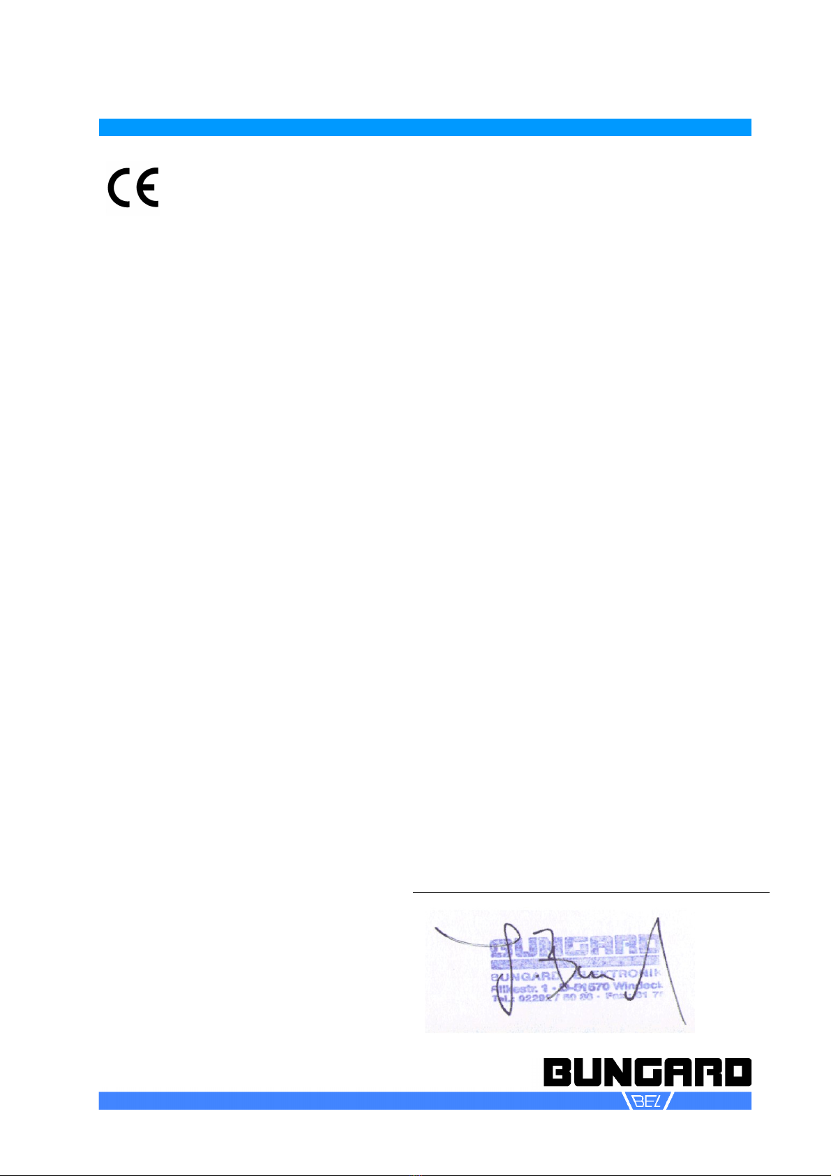
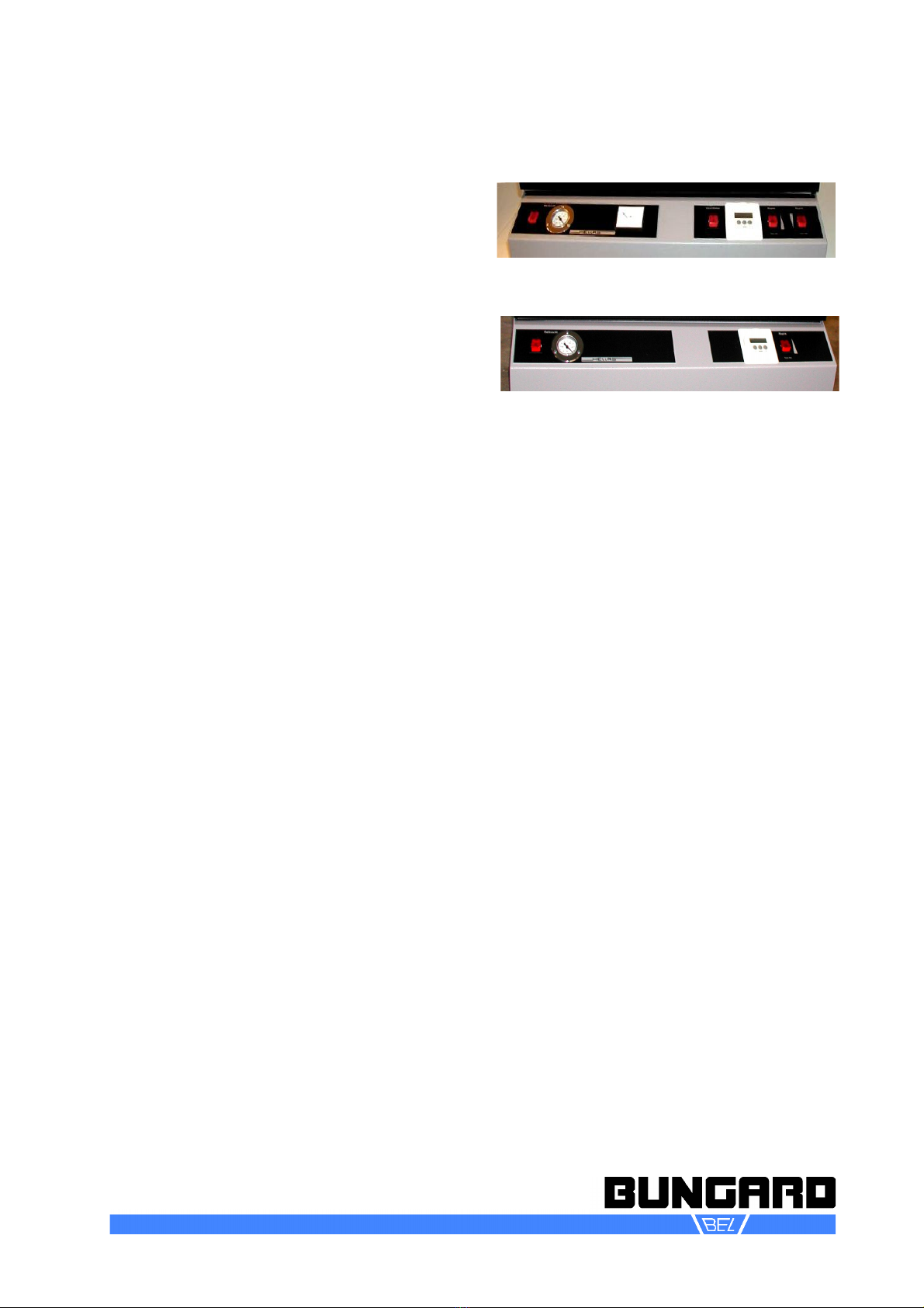
Locate the switches, the timer, the ampere meter
and the vacuum control on the front panel of the
unit (Hellas-E: no Amperemeter). All to the left,
there is a switch controlling the vacuum pump. Put
it into its ON position. The pump will start running
and the indicator lamp in the switch will light.
Within a few seconds, the pump will have
evacuated the air between the frame and the glass
plate. The vacuum indicator will show approx. 0.8
bar.
The polyester foil is structured to allow an easy
and complete evacuation on the whole surface.
Nevertheless, there might remain an air cushion
between the artwork and the board. Wipe over the
polyester foil with your hand or with a soft cloth to remove any rest of air. Using the handle, smoothly
close the cover.
elect single or double side exposure by turning on the appropriate switches for the upper and lower
set of tubes. They are located to the right of the timer. Hellas-E: You may switch on only the upper
unit.
To start the exposure, follow the instructions below to operate the electronic timer. Alternatively you
can operate Hellas in continuous mode. To do so turn on the switch left to the timer. Turn the switch
off to stop the continuous operation mode. The indicator lamp in the switch is lit during automatic
exposure and continuous operation as well. The switch is marked ventilator to indicate that there is
a built-in fan always running together with the lower tube set. Hellas-E: there is no switch for
continuous exposure.
Timer
The exposure time is controlled by a digital-read-out and digital-adjustable timer. The range of time
is from 1 second to 9 minutes 59 seconds. The device supports easy time pre selection and recall
by one hand operation and can be run in stop-and-go turns.
On the timer front panel there are the LCD time display and the three buttons MODE, + and -.
To adjust the desired exposure time, press the + or - buttons accordingly. Keeping one of them
down makes the settings change faster.
To start exposure, press the MODE button once. The remaining time is displayed continuously on
the LCD display. The process is interrupted and restarted for the remaining time at each time the
MODE button is pressed. The timer beeps several times when exposure has finished.
To redisplay the previous setting, press the MODE button once. You may then use the +/- buttons to
change the setting or just restart the unit by pressing the MODE button.
Do not switch off the vacuum during exposure! With the artwork loosing contact to the board, severe
under-cut may result.
When having completed the exposure, open the cover, switch off the vacuum and open the frame.
Never lift the frame with the vacuum pump running. Abnormal usage of the frame would result.
The intensity and spectre of the UV light from the fluorescent tubes can be compared to that of skin
tanning sets: It may irritate your eyes. You should therefore avoid to look directly into the light for a
longer time.
Hellas
Hellas-E
Bungard Elektronik GmbH & Co. KG, Rilkestraße 1, 51570 Windeck – Germany
Tel.: +49 (0) 2292/9 28 28 - 0, Fax: +49 (0) 2292/9 28 28 - 29, E-mail: [email protected]

hellas-manual-en Page 7 / 9
Maintenance
There is only little maintenance necessary for the HELLA exposure set. The vacuum pump, for
instance, is maintenance free. To protect it from dirt and dust, there is a filter put in front of it.
The fluorescent tubes are subjected to wear. After about one or two years, they should be replaced.
A reduced Amps reading on the emission control meteor dark shadows appearing at the tubes
ends indicate that they should be renewed.
To do so, at first disconnect the exposure set from the main supply. Carefully lift the crystal glass
plate and pull off the small blue vacuum hose to get access to the lower tube set. Turn the tubes
along their axis until they snap off from the fittings. Replace them only with tubes of the same type
and strength. Check that the new tubes are well locked. It is recommended also to replace the
starters.
We want to tear your special attention to a careful maintenance of the vacuum foil. It should be
cleaned regularly using water and a soft detergent. Do not use solvents.
Be extremely careful not to contaminate the foil with spots of developer or etching liquid.
Do not put pieces with an height of more than about 5 mm under the frame. This could lead to
serious deformation or even cuts in the foil.
Spare Part List
640001 HELLA Vakuumrahmen HELLA Vacuum frame
640002 HELLA Reparatur Vakuumrahmen repair of HELLA vacuum frame
Bungard Elektronik GmbH & Co. KG, Rilkestraße 1, 51570 Windeck – Germany
Tel.: +49 (0) 2292/9 28 28 - 0, Fax: +49 (0) 2292/9 28 28 - 29, E-mail: support@bungard.de

hellas-manual-en Page 8 / 9
640003 HELLA Vakuumpumpe HELLA vacuum pump
640005 HELLA Glasplatte HELLA Glasplatte
640006 HELLA Leuchtstoffröhre HELLA superactinic tube
640007 HELLA tarter HELLA tarter
640008 HELLA Lüfter HELLA Lüfter
640009 HELLA Amperemeter HELLA Amperemeter
640010 HELLA Manometer HELLA Manometer
640011 Hellas Drossel Hellas coil for superactinic tubes
6000 chaumklebeband für Hellas
Glasplatte/Vakuumrahmen 2 m
Foam tape for Hellas glass plate / vacuum
frame 2 m
HELLA Reparatur-Kit
Vakuumrahmen(Folie+Dichtung)
repair set of HELLA vacuum frame(black
rubber tape & transparent plastic sheet)
Guarantee
All machines are submitted before distribution to examination on function and continuous operation
firmness. On the machine we grant a work warranty of 12 months to our customers starting from purchase
date on accuracy in material and processing. We warrant at our choice by exchange of incorrect parts or
by repair of the machine in our house. Old parts change into our possession.
Disclaimer of arranty
Bungard GmbH & Co.KG reserves the right to change or enhance its machines or machine specifications
according to its judgement, if necessary. Bungard cannot be held responsible to implement aforesaid
changes into machines sold already.
Bungard Elektronik GmbH & Co. KG, Rilkestraße 1, 51570 Windeck – Germany
Tel.: +49 (0) 2292/9 28 28 - 0, Fax: +49 (0) 2292/9 28 28 - 29, E-mail: sup[email protected]

hellas-manual-en Page 9 / 9
Bungard products and services are liable to the current prices and conditions, which are subject to
change.
The instructions and definitions in this document are also subject to change and mark no assurance on
the part of Bungard.
This manual contains informations of the Bungard Hellas and is the translated English version.
Please regard the “ ales terms and delivery conditions”. These are available after fulfilment of the
contract. We don't furnish a guarantee or warranty in cause of damages at material or hurts of people
because of
Incorrect use of the machine
Wrong setup, installing and operating of the machine or incapable service
Use of the machine with defective safety equipment
Non-observance of the service manual in regard to transport, stocking, setup, installation and service of
the machine
Unlicensed modifications at the machine
Incorrect or incomplete repairs
Destructive force effect at the machine in cause of foreign objects or external use of force
Use of non-original spare parts
normal wear parts.
We cannot accept subsequent claims from damage or destruction of work pieces worked on in the
machine, because we have no knowledge or control over the operating conditions at your site. This is
valid in a general manner also for requirements from damage to articles, buildings and persons as well as
the environment.
We do not warrant that the function of the machine will meet the customer's requirements or that the
operation of the machine will to this regard be error free.
In no event will we be liable to the customer for any incidental, consequential, or indirect damages of any
kind, including loss of profit and prosecution for environmental pollution, even if we could have been
aware of the possibility of such damages.
All information was arranged with great care. We reserve ourselves however mistake and technical
changes without previous announcement.
Running the machine in corroding, humid, dusty, extremely hot or explosive atmosphere happens at
the operator's own risk and responsibility.
We explicitly exclude any warranty for damages resulting from running the machine in in corroding,
humid, dusty, extremely hot or explosive atmosphere.
Copyright
© 2022 Bungard Elektronik GmbH & Co. KG
Bungard Elektronik GmbH & Co. KG, Rilkestraße 1, 51570 Windeck – Germany
Tel.: +49 (0) 2292/9 28 28 - 0, Fax: +49 (0) 2292/9 28 28 - 29, E-mail: support@bungard.de
This manual suits for next models
3
Table of contents
Other Bungard Laboratory Equipment manuals
Popular Laboratory Equipment manuals by other brands

WPI
WPI LWCC-M-10 instruction manual

Hettich
Hettich Rotolavit II operating instructions

Cole Parmer
Cole Parmer RS-200 Series instruction manual

Stratus
Stratus cerillo quick start guide

Parker Balston
Parker Balston FID 1000 Installation, operation and maintenance manual

Qiagen
Qiagen TissueLyser II troubleshooting guide