BUNKER RAMO AMPHENOL 157-12140 User manual

TERMINATIONEQUIPMENT
INSTRUCTIONMANUAL
TELE-PIERCE
P/N356-246

OPERATIONANDSERVICE
INSTRUCTIONS
AMPHENOL
157SERIESTELE-PIERCE™
MULTI-WIRETERMINATIONTOOL
356-246
AMPHENOLTERMINATIONSYSTEMS
1830S.54THAVENUE
CICERO,IL60650
(312)656-5744
SPECIFICATIONNO.
D2-603-356-246
ISSUEDAUGUST,1977

TABLEOFCONTENTS
SectionPage
IINTRODUCTION
1-1.Description1
1-2.Installation2
1-3.CustomerServices2
1-4.Application4
IISET-UPANDADJUSTMENTS
2-1.ToothCarrierArms5
2-2.ToothPlates5
2-3.ChangeoverProceduresforPlug
andReceptacleConnectors. 5
2-4.SelectionofLocatingPin....6
IIIOPERATINGINSTRUCTIONS
3-1.LoadingtheConnector7
3-2.CablePreparation7
SectionPage
3-3.WirePositioning7
3A. TerminatingtheConnector...8
3-5.RemovaloftheConnector....9
3-6.InspectingWireTermination..10
ACCESSORIES10
IVMAINTENANCEANDREPAIR
4-1.General11
4-2.Cleaning11
4-3.Lubrication11
4-4.AdjustmentofToothPlates...11
4-5.TROUBLESHOOTING12
VPARTSLIST
5-1.General13
5-2.RunningSpares13

SECTIONI
INTRODUCTION
1-1.DESCRIPTION(Figure1-1)
a.TheAmphenolTele-Pierce™Multi-Wire
TerminationToolisa hand-operateddevicefor
fieldorlow-volumeproductioninsertionofpre-
paredconductorsintoAmphenolSolderless
Micro-PierceSeries-157telephonecablecon-
nectors.TheToolwillprocess14,24,36,50,
and64-conductorcables(7,12,18,25,and32
pairsrespectively),lookunder"1-4.Application"
fordetails.
b.Theconnectorisfirstinsertedintothe
fixture.Thenthepreparedcable,withthejacket
strippedbackseveralinches,isclampedinthe
fixture.Theindividualwiresarethenfannedout
andfedintotheproperopeningsinthewire
comb.Whenallwiresareinpositionaccordingto
thecablecolorchart,thecrimphandlesare
pressedtogether.Thetoolstuffsthewires,
piercestheinsulationtomakecontactwiththe
terminals,andcutsoffexcesswire.Thecrimp
handlesarethenopened,theconnectorreleased,
andtheterminatedcableassemblyremovedfrom
thetool.

1-2.INSTALLATION
TheAmphenolTele-Pierce™ Multi-Wire
Toolisportableandself-contained.Installthe
toolforuseasfollows:
a.Openthecarryingcase,liftouttheTele-
Pierce™Toolonitsportablebaseandsetthe
caseaside.
b.LocatetheToolwithitsbaseona suitable
worklocation
1-3.CUSTOMERSERVICES
TheTele-Pierce™Toolhasbeenadjusted
andtestedforqualityreliabilitybeforeitis
shipped.
Inquiriesforrepairs,fieldservice,andspare
partsonterminationequipmentshouldbedi-
rectedto:
AmphenolTerminationSystems
1830S.54thAve.
Cicero,Illinois60650
(312)656-5744
24HourFieldServiceNumber

1-4.APPLICATION
TheAmphenolTele-Pierce™Multi-Wire
Tool(P/N356-236)isdesignedtobeusedwith
connectorsandwirecombinationsbelow:
AMPHENOL
PARTNUMBER CONNECTORDESCRIPTION
LOCATING
PIN
TURRET
NUMBEROF
CONTACT WIRE
SIZE
157-12140
157-12240
157-12360
157-12500
157-12640
157-22140
157-22240
157-22360
157-22500
157-22640
157-12500-3
157-22500-3
157-32140
157-32240
157-32360
157-32500
157-42140
157-42240
157-42360
157-42500
157-52140
157-52240
157-52360
157-52500
157-62140
157-62240
157-62360
157-62500
157-72500-3
157-82500-3
157-72140-8
157-72240-8
157-72360-8
157-72500-8
157-72640-8
157-82140-8
157-82240-8
157-82360-8
157-82500-8
157-82640-8
RackandPanel,Plug(MountingHole.103)
RackandPanel, Plug(MountingHole.103)
RackandPanel,Plug(MountingHole.103)
RackandPanel,Receptacle(FloatBushing)
RackandPanel, Receptacle(FloatBushing)
RackandPanel,Receptacle(FloatBushing)
RackandPanel,Plug(MountingHole.185)
RackandPanel,Receptacle(MountingHole.185)
TopCableEntry— Plug(LooseInsert)
TopCableEntry- Plug(LooseInsert)
TopCableEntry— Plug(LooseInsert)
PanelMountReceptacle(SpringLatches)
SideCableEntry- Plug(LooseInsert)
TopCableEntry- Receptacle(SpringLatches)
TopCableEntry— Receptacle(SpringLatches)
RunningCable- Plug,SteelHood
RunningCable- Receptacle,SteelHood
RunningCable- Plug,PlasticHood
RunningCable— Receptacle,PlasticHood
RunningCable- Receptacle,PlasticHood
RunningCable— Receptacle,PlasticHood
RunningCable- Receptacle,PlasticHood
B 14
B 24
B 36
B 50
B 64
T 14
T 24
T 36
T 50
T 64
A 50
A 50
T 14
T 24
T 36
T 50
T(RL) 14
T(RL) 24
T(RL) 36
T(RL) 50
T 14
T 24
T 36
T 50
T(RL) 14
T(RL) 24
T(RL) 36
T(RL) 50
C 50
C 50
C 14
C 24
C 36
C 50
C 64
C 14
C 24
C 36
C 50
C 64
24,26
24,26
24,26
24,26
24,26
24,26
24,26
24,26
24,26
24,26
24,26
24,26
24,26
24,26
24,26
24,26
24,26
24,26
24,26
24,26
24,26
24,26
24,26
24,26
24,26
24,26
24,26
24,26
24,26
24,26
24,26
24,26
24,26
24,26
24,26
24,26
24,26
24,26
24,26
24,26
T(RL)- TopEntryAdapterKitP/N357-247Required(RemoveSpringLatch)
3/4(blank)

SECTIONII
SET-UPANDADJUSTMENTS
2-1.TOOTHCARRIERARMS
Swingthehandlescontainingthetooth
platesbacktotheirreststops.
2-2.TOOTHPLATES(Figures2-1and2-2)
Checkthetoothplatestoinsurethatthey
areproperlysetfortheconnectorreceptacleor
plugtobeterminated.
2-3.CHANGEOVERPROCEDURESFORRE-
CEPTACLE(FEMALE)ANDPLUG(MALE)
CONNECTORS(Figures2-1and2-2)
a.Loosentheadjustmentclampscrewinthe
centerofbothtoothcarrierarmsbyturningina
CCW(counter-clockwise)direction.
b.Pushthepunchadjustmentslideonboth
carrierarmsdownwardsothewordFEMALEis
visibleabovetheslide.Atthistimea redlinewill
appearonthearm.ThewordFEMALEandthis
redlineindicatesthetoolissettoterminatethe
receptacle(female)connector.
c.Whenthetwoslides(describedabove)are
pushedupwardsothewordMALEisvisible
beneaththeslides,thetoolissettoterminate
plug(male)connectors.
d.PushtheslideforeitherFEMALEor
MALEsothetoothplateswillbesetasfar
forwardastheywillgo.Whileholdingthetooth
platesinthisposition,tightentheadjustment
clampscrewonbothcarrierarmsbyturningCW
(clockwise).
NOTE
Makecertainbothhandlesareonsame
applicablesetting(seeFigure2-2).
5

2-4.SELECTIONOFLOCATINGPIN(FIGURE
2-3
a.Threelocatingpinsareavailabletolocate
connectorwithholeinconnectorshell.
b.Toaccommodatevariousconnectors,turn
thelocatingpinturretsothecorrespondingletter
toa particulartypeconnectorislinedupwith
cableclampandfanningcombs(see1-4appli-
cation).
A— .173— panelmount
B— .100— panelmount
C- .083- runningcable
6

SECTIONIII
OPERATINGINSTRUCTIONS
3-1.LOADINGTHECONNECTOR(Figure3-1)
a.Squeezethecombleverslocatedonthe
frontofthetoolinwardstoopenthecombs.
b.Whenapplicable,withthe90-degreecable
strainreliefendbracketontheconnectorshell
towardsthecableclampofthetool,insertthe
connectorallthewaydownbetweenthefanning
combs,positionoverthelocatingpin.
c.Releasethecombleverstolockthecon-
nectorinposition.Toinsureproperseatingalso
closethecombsbyhand.Iftheconnectorre-
mainsupbetweenthecombs,pushitdownwhile
closingthecombsbyhand.
d.Checkthelineuptoinsurethatthefirst
setofslotsontheconnector(towardthecable
strainreliefendbracket)areinlinewiththefirst
setofslotsonthecombs.Ifpositionedcorrectly,
locatingnibsoneachcombwillhaveenteredthe
connectorbetweenthefirstandsecondbarrieron
allconnectorsizesupto50contacts.(Onthe
64-contactsizeconnectorlocatingnibswillalso
enterbetweenthelasttwobarriersoneachside.)
3-2.CABLEPREPARATION(Figure3-2)
a.Preparethecableaccordingtolocalprac-
tice.Strippingthejacketbacksixtoseveninches
andpresortingofthewiresintothemajorcolor
groupsisrecommended.
b.Withthecableenteringfromtherearof
thetool,pushthecableintothecableclamp
lininguptheendofthecablejacketapproxi-
matelyhalfwaybetweentheendofthecon-
nectorblockandthe90-degreecablestrainrelief
endbracket.Itisadvisabletopositionthefirst
colorgroupofwirestobeuseddownward.
c.Bendtheunwantedcolorgroupsofwire
back,topermiteasyaccesstoeachpair.
3-3.WIREPOSITIONING(Figures3-3and3-4)
a.Selectanduntwistthefirstpairofwires
perthecolorcodechart,oneineachhand.
7

b.Positionthewiresothatitlaysoverthe
topoftheindexfingerandisheldtautand
guidedwiththethumb.
c.Keepthewiretautandslideyourindex
fingerdownthewiretoapproximatelytheslot
thewireistobeinserted.Relaxthetensionon
thewireandretractthetipofyourindexfinger
tothetipofyourthumb.Holdingthewireat
thispoint,a distinctbendshouldhavebeen
formed.
d.Usinga slightbackwardanddownmotion,
moveyourhandstowardthecombs,guidingboth
wiresintotheirappropriateslots.
e.Pullbothwirestautinanoutwardand
downmotion,beingcarefulnottoexertexcessive
tensiononthewiressothatthecombsopen.
f.Keepingthewirestautallowthemtoslip
thruyourfingerswhileyourhandsaremoving
straightoutanddownguidingthewiresthruthe
lowerslotsandintotheretentionsprings.
g.Repeattheaboveprocedureforeachsuc-
ceedingpairofwiresinthefirstcolorgroup;be
suretheyareinsertedintosucceedingslots.
h.Bendthenextcolorgroupup,perthe
colorcodechart,tofacilitatesortingasdonefor
thefirstgroup.
i.Proceedtofanthewiresintotheirproper
slots,andrepeatforeachcolorgroup.Asslots
fartherfromthecablearewired,allowthewires
toslipthruyourhandsandoveryourindex
8
fingerwhilekeepingthewiretaut,stoppingat
theappropriateslot.Thismethodwillstraighten
anybendsinthewire,allowforeasierslot
selection,andcreatethedesiredwirebendnear
theappropriateslot.
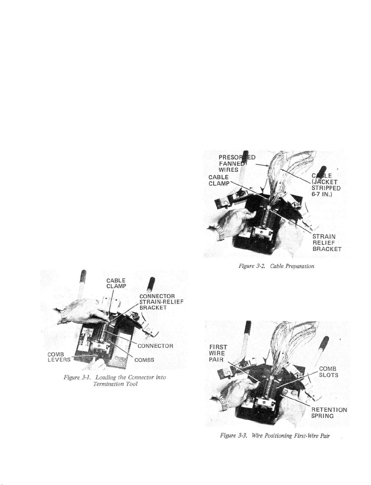
j.Whenallthewireshavebeenfannedinto
thecomb,inspectthemforpropercolorcode,
andbesureallthewiresrunthrutheirrespective
slotsandareintheretentionspringoneachside
ofthetool.
3-4.TERMINATINGTHECONNECTOR(Fig-
ures3-5and3-6)
a.Swingthetoothcarrierarmscontainingthe
toothplatespartiallyintothecombsuntilthey
touchthefirstwires.
b.Swingthecrimphandlesforwardmaking
suretheleversengagethepivotpins(9).
c.Continuetoswingthecrimphandlesto-
getheruntilthetoothcarrierarmsarecoveredby
theedgesofthearm retainer"T".Atthistime
botharmsshouldbeupagainstthepositivestop
andinparallelposition.Theratchetshouldnow
release.
d.Allwireshavenowbeencutandtermi-
nated.
NOTE
Ratchetinsuresthathandlesmustbefully
closedagainstarmretainerbeforeopen-
ing.Onlyinthiswaywilla complete,
reliableterminationbemade.

SECTIONIII
OPERATINGINSTRUCTIONS
3-1.LOADINGTHECONNECTOR(Figure3-1)
a.Squeezethecombleverslocatedonthe
frontofthetoolinwardstoopenthecombs.
b.Whenapplicable,withthe90-degreecable
strainreliefendbracketontheconnectorshell
towardsthecableclampofthetool,insertthe
connectorallthewaydownbetweenthefanning
combs,positionoverthelocatingpin.
c.Releasethecombleverstolockthecon-
nectorinposition.Toinsureproperseatingalso
closethecombsbyhand.Iftheconnectorre-
mainsupbetweenthecombs,pushitdownwhile
closingthecombsbyhand.
d.Checkthelineuptoinsurethatthefirst
setofslotsontheconnector(towardthecable
strainreliefendbracket)areinlinewiththefirst
setofslotsonthecombs.Ifpositionedcorrectly,
locatingnibsoneachcombwillhaveenteredthe
connectorbetweenthefirstandsecondbarrieron
allconnectorsizesupto50contacts.(Onthe
64-contactsizeconnectorlocatingnibswillalso
enterbetweenthelasttwobarriersoneachside.)
3-2.CABLEPREPARATION(Figure3-2)
a.Preparethecableaccordingtolocalprac-
tice.Strippingthejacketbacksixtoseveninches
andpresortingofthewiresintothemajorcolor
groupsisrecommended.
b.Withthecableenteringfromtherearof
thetool,pushthecableintothecableclamp
lininguptheendofthecablejacketapproxi-
matelyhalfwaybetweentheendofthecon-
nectorblockandthe90-degreecablestrainrelief
endbracket.Itisadvisabletopositionthefirst
colorgroupofwirestobeuseddownward.
c.Bendtheunwantedcolorgroupsofwire
back,topermiteasyaccesstoeachpair.
3-3.WIREPOSITIONING(Figures3-3and3-4)
a.Selectanduntwistthefirstpairofwires
perthecolorcodechart,oneineachhand.

3-5.REMOVALOFTHECONNECTOR(Fig-
ures3-7and3-8)
a.Afterratchetisreleased,swingthecrimp
handlesallthewaybacktothetoothcarrier
arms,bringingtheteethoutoftheconnector
blockandcombs.
b.Swingthetoothcarrierarmsbacktotheir
reststops.
c.Pressthecomblevers,locatedinthefront
ofthetoolinwardtoopenthecombs.
d.Pullthecablefromtheclampandremove
thecableandconnectorassemblyoutofthe
terminationtool.
e.Removethecut-offwiresfromthereten-
tionspringanddiscard.
3-6.INSPECTINGWIRETERMINATION(FIG-
URES3-9AND3-10)
a.Inspectconnectorforpropertermination.
Doubledimples("double-bubble")inthewire
pierceareashouldbeclearlyvisibleanduniform
onbothsidesofconnectors.
b.Endofindividualwiresshouldbeatleast
0.050inchpastthepiercearea.
9

SECTIONIV
MAINTENANCEANDREPAIR
4-1.GENERAL
Theinstructionsinthefollowingpara-
graphsareimportantforthecorrectoperationof
thewireterminationtool.Figure5-1isanex-
plodedviewofthetoolandSectionV contains
thepartslist.
4-2.CLEANING
Toinsurethatwireinsertiondepthiscor-
rect,adjustsetscrew(28)onrighthandtooth
carrier(32)asfollows(refertoFigure5-1):
a.SetslidingpunchadjustmenttoFEMALE
positionperparagraph2-3b.
b.Closetoolhandlestogether.
Periodicallywipeoffalloutersurfacesof
theterminationtoolwithlightlyoiledclothto
removedustandgritandreducethepossibilityof
rust.Spacesbetweencombteethandtoothplate
teethandcrevicesshouldbecleanedusinga
clean,drypaintbrush.
4-3.LUBRICATION
Periodicallylubricateallwearareas(see
Figure5-1)oncombs(8),combspreaderpin
(31),comblevers(22,23),toothcarriers(26,
32),pivotpins(22,9)andspringends(17)by
applyinga thincoatofMolykoteNumber505.
Wipeoffallexcesslubricant.
4-4.ADJUSTMENTOFTOOTHPLATES
c.Checkthatspacingbetweentoothplates
(25)is0.095-0.105inch.Ifnotasspecified,
loosennut(29)andadjustsetscrew(28)for
correctspacingandtightennut.
d.SetslidingpunchadjustmenttoMALE
positionperparagraph2-3c.
e.Checkthatspacingbetweentoothplates
(25)is0.185-0.195inch.
f.Setscrew(28)shouldcomeincontactwith
lefthandtoothcarrier(26)withtoolhandles
closedtogetherafterfinaladjustment.
NOTE
Whenadjustingtoothplates(25)besure
thattoothplateisbearingagainstpunch
adjustmentblock(23)beforetightening
adjustmentclampscrew(61).
NOTE
Abovedimensionsarepre-setatthefac-
toryandshouldnothavetobere-set
undernormalconditions.
11

4-5.TROUBLESHOOTING
PROBLEMORSYMPTOM POSSIBLECAUSESAND
CORRECTIVEACTION
Tooldoesnotcutoffwiresproperly -Makesurethat"ArmRetainer"("T")Figure3-6
infrontoftoolistightened.
-Inspectcuttingedgesontoothplatesandcombs.
Ifcuttingsurfacesaredull,replacepartswithnew
ones.
-Makesurethatpunchadjustmentslidesholding
toothplatesareproperlytightened.
Tooldoesnotstuffwirestoproperdepth -Makesurethatbothhandlesarefullyclosedwhen
(no"double-bubble") terminatingconnector.
—Makesurethatcarrierarmsaresetforproper
connectortype,maleorfemale(Figure2-2).
-Checkforcorrectspacingbetweentoothplates
(paragraph4-4).
Difficultieswhenloadingconnector —Screwsholdingconnectorpadmighthaveworked
betweencombs loose.Checkpositioningofconnectoronpad.
Connectorshouldberestingonpadsothatcombs
areclosingoverconnectortop.Tipofscrews
holdingconnectorpadshouldbeapprox.flush
withtopofpad.Whenadjustmentisnecessary,
removetoolfrombase,correctthesettingwith
thetwosocketheadcapscrews.Checkthat
locatorpinistheappropriatepinforthe
connector.
Combsdonotcloseproperly -Checksettingofconnectorpad(seelastpara-
graph).
-Combsmightbestickingduetodirt,wirecut-offs
intrack.
-Combextensionspring(underneathtool)
stretchedorbroken,replacewithnewone.
Toothplatesbindwithcombswhen -Makesurethatpunchadjustmentslidesholding
openingtoolaftertermination toothplatesaretightened.
-Makesurethatcombsareproperlyclosed.
Ratchetdoesnotopen -Checkthatarmsarefullyclosed.
-Checkthatcarrierarmsaresetforproper
connector.
-Releaseratchetpawlbytriggeringspringrelease
onleftcarrierarm.
12

SECTIONV
PARTSLIST
5-1.GENERAL
ReplacementpartsfortheAmphenolwiretermina-
tiontool areshownintheexplodedview,Figure5-1,and
intheaccompanyingpartslist.
5-2.RUNNINGSPARES
Partsrecommendedtobestockedbythecustomer
asrunningsparesareindicatedbyanasterisk(*)inthe
UNITSPERASSEMBLYcolumninthepartslist.
FIG.&
UNITS
INDEX DESCRIPTION
PER
NO.
PARTNO. 12 3 4 5 6 7
ASSY.
5-1-
356-246
356-236-7
356-236-44
TERMINATIONTOOL,57SERIES
1
356-246
356-236-7
356-236-44
.BASE 1
2
356-246
356-236-7
356-236-44
.PLUNGER,SPRING,VLIERBH54N 2
3
356-236-43
.SCREW,CAP,SOCKETHD,1/4-20x 1-3/4
2
'4
356-236-12
.BLOCK,CABLEGUIDE 1
5
356-236-42
.PIN,DOWEL,0.2500-0.2502x 1-1/4 2
6
356-236-41
.SCREW,FLATHD,SOCKET,NO.10-32x 3/4 1
7
356-236-27
356-236-6
.SPACER,CABLECLAMP 1
8
356-236-27
356-236-6
.COMB
2*
9
356-236-40
.PIN,DOWEL,0.250x 1 2
10
356-236-15
.RETAINER,ARM 1
11
356-236-39
.SCREW,CAP,SOCKETHD,1/4-10x 1-3/4
1
12
356-236-14
356-236-16
.PLATE,LOCATINGPAD 1
13
356-236-14
356-236-16
.SPRING,COMPRESSION 2
14
356-236-38
.SCREW,CAP,SOCKETHD,No.10-24x 1/2. 2
15
356-236-19
.LEVER,COMB,RH -1
16
356-236-37
.SCREW,SHOULDER 2
17
356-236-8
.SPRING,EXTENSION
1*
18
356-236-9
.SPRING,EXTENSION 2
19
356-236-36
.SCREW,CAP,BUTTONHDSOCKET,No.10-24x 1/4 4
20
356-236-1
.HANDLE,CRIMP(LH& RH) 2
21
356-236-70
.SLIDE,PUNCHADJUSTMENT 2
22
356-236-10
356-236-66
356-236-69
.PIN,HANDLE,CARRIERARM 2
23
356-236-10
356-236-66
356-236-69
.BLOCK,PUNCHADJUSTMENT 2
24
356-236-10
356-236-66
356-236-69
.PLATE,CLAMP 2
25
356-236-2
.PLATE,TOOTH
2*
26 356-2364 . CARRIER,TOOTH,LH
27
356-236-60
356-236-34
.TURRETASSEMBLY
28
356-236-60
356-236-34
.SETSCREW,SOCKET,FLATPT,No.10-24x 3/4
29
356-236-33
.NUT,HEX,JAM,No.10-24
30
356-236-21
.GRIP,PLASTIC
31
356-236-3
356-236-5
.PIN,COMBSPREADER
32
356-236-3
356-236-5
.ARM,TOOTHCARRIER,RH
33
356-236-30
.NUT,HEX,1/4-20
34a
356-236-47-3
.PIN,LOCATING,0.173in.dia
34b
356-236-47-2
.PIN,LOCATING,0.100in.dia
34c
356-236-47-1
.PIN,LOCATING,0.083in.dia
35
356-236-51
.CASE,CARRYING
36 . INSTRUCTIONMANUAL(notshown)
37 356-23649
356-236-32
356-236-22
.RUBBERPAD
38 356-23649
356-236-32
356-236-22
.SCREW,FLATHD,No.10-24x 1-3/4
39
356-23649
356-236-32
356-236-22
.LEVER,COMB,LH
40 356-23648 . BASE,REMOVABLE
41
356-236-24
.LABEL
42
356-236-64
.SPRING
43
356-236-71
.CLAMP,CABLE
44
356-236-29
.SCREW,DRIVE,RDHD,No.W2,0.098x 1/4
45
356-236-73
356-236-45
.SCREW,PHILLIPSPANHD,TYPEB,No.6 x 5/16
46
356-236-73
356-236-45
.CHART,COLOR,MALE
47 356-23646 . CHART,COLOR,FEMALE
48
356-236-50
356-236-52
.INSTRUCTIONSHEET
49
356-236-50
356-236-52
.DIRECTIVELABEL
50
356-236-50
356-236-52
.SPACER,FOAM
51
356-236-63
.DETENT
52
356-236-65
.RING,RETAINING
53
356-236-55
.PIN,RETAINING,RATCHET
54
356-236-62
.SCREW,ADJUSTMENT,RATCHET
55
356-236-59
.SETSCREW,SHAFT,RATCHET,No.10-32x 1/4
56
356-236-74
.SHAFT,RATCHET
57
356-236-54
.LEVER,RATCHET
58
356-236-58
.PLUG,SPRING,RATCHET
59
356-236-57
.SPRING,LEVER,RATCHET
60
356-236-56
.SETSCREW,SOCKET,FLATPT,No.8-32x 1/4
61
356-236-68
.SCREW,CLAMP,ADJUSTMENT 2

13/14(blank)
This manual suits for next models
39
Table of contents