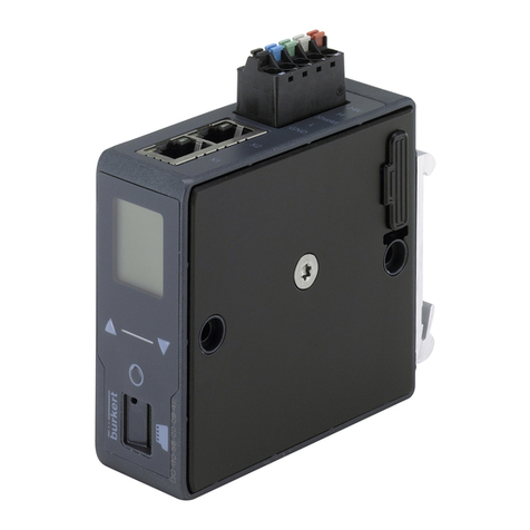
Burkert FieldConnect ME63 User manual

Operating instructions
Type ME63
FieldConnect
Fieldbus gateway

We reserve the right to make technical changes without notice.
Technische Änderungen vorbehalten.
Sous réserve de modifications techniques.
© Bürkert Werke GmbH & Co. KG, 2020–2023
Operating Instructions 2307/02_EUen_00815318 / Original DE

3
Type ME63
Content
1THE OPERATING INSTRUCTIONS ........................................................................................................6
1.1 Symbols........................................................................................................................................6
1.2 Denitionofterms........................................................................................................................6
2INTENDED USE ......................................................................................................................................7
3BASIC SAFETY INSTRUCTIONS ...........................................................................................................7
4GENERAL NOTES...................................................................................................................................8
4.1 Contactaddresses.......................................................................................................................8
4.2 Warranty .......................................................................................................................................8
4.3 InformationontheInternet..........................................................................................................8
5PRODUCT DESCRIPTION......................................................................................................................9
5.1 Generaldescription......................................................................................................................9
5.2 Devicefunctions ..........................................................................................................................9
5.3 Systemmonitoring.....................................................................................................................10
6TECHNICAL DATA ................................................................................................................................11
6.1 Standardsanddirectives...........................................................................................................11
6.2 Operatingconditions .................................................................................................................11
6.3 Electricaldata ............................................................................................................................11
6.4 Devicelabelling..........................................................................................................................12
6.4.1 Device top side labelling.............................................................................................12
6.4.2 Left and right device side labelling .............................................................................13
6.5 IndustrialEthernet......................................................................................................................13
6.5.1 PROFINET IO..............................................................................................................13
6.5.2 EtherNet/IP .................................................................................................................14
6.5.3 Modbus TCP...............................................................................................................14
6.5.4 EtherCAT.....................................................................................................................14
6.5.5 CC-LinkIEeldbasic .................................................................................................15
6.5.6 OPC UA ......................................................................................................................15
7INSTALLATION......................................................................................................................................16
English

4
Type ME63
7.1 Installingthedevice...................................................................................................................16
7.2 Electricalconnectionofthedevice...........................................................................................16
7.2.1 Assignment of the connections ..................................................................................17
7.3 CombiningME6xmodules ........................................................................................................19
7.3.1 Module connections for the power supply .................................................................19
7.3.2 Simpliedpowersupplyplan .....................................................................................21
7.3.3 Combining ME66 modules .........................................................................................23
7.4 CombiningdierentMEmodules..............................................................................................24
8 MEMORYCARD ...................................................................................................................................25
9START-UP WITH AN EXTERNAL CONTROLLER ................................................................................26
9.1 CablingofbüSnetworks ...........................................................................................................26
9.2 Start-uplesanddescriptionoftheprocessdataandparameters........................................26
9.3 Advancedgatewayfunctionalities ............................................................................................26
10 START-UPWITHBÜRKERTCOMMUNICATOR ..................................................................................27
10.1 Userinterface.............................................................................................................................27
10.2 ConnectingthedevicetotheBürkertCommunicator .............................................................28
10.3 ProtocolsettingsforconnectingthedevicetothePLCnetwork............................................28
10.3.1 Selecting the protocol.................................................................................................28
10.3.2 Entering the EtherCAT address (Station Alias)............................................................28
10.3.3 EnteringaPROFINET,EtherNet/IP,ModbusTCPorCC-LinkIEeld
basic address .............................................................................................................28
10.4 Conguringtheeldbusgateway .............................................................................................29
10.4.1 Downloadingagatewayconguration ....................................................................... 29
10.4.2 Editingagatewayconguration ................................................................................. 29
10.4.3 Creatinganewgatewayconguration .......................................................................29
10.5 ConguringthebüSnetwork.....................................................................................................40
11 START-UP USING A WEB SERVER .....................................................................................................41
11.1 Functionofthewebserver ........................................................................................................41
11.2 MakingaconnectiontothewebserverviaBürkertCommunicator .......................................41
11.3 Establishingaconnectiontothewebserver............................................................................41
11.4 Loggingontothewebserver.....................................................................................................42
English

5
Type ME63
11.5 Passwords..................................................................................................................................43
11.5.1 Change password.......................................................................................................43
11.5.2 Factory reset of password ..........................................................................................43
11.6 Conguringthedevice............................................................................................................... 43
12 OPC UA.................................................................................................................................................44
12.1 Generaldescription....................................................................................................................44
12.2 EstablishingaconnectiontoOPCUA ......................................................................................44
12.2.1 Settings on the device ................................................................................................44
12.2.2 Settings for the OPC UA client ...................................................................................45
12.3 Servercerticate........................................................................................................................45
13 DISPLAYELEMENTS ...........................................................................................................................47
13.1 LEDsforindicatingthebusstatus............................................................................................47
13.1.1 PROFINET IO..............................................................................................................47
13.1.2 EtherNet/IP .................................................................................................................48
13.1.3 Modbus TCP...............................................................................................................50
13.1.4 EtherCAT.....................................................................................................................51
13.1.5 CC-LinkIEeldbasic .................................................................................................52
13.2 LEDforindicatingthedevicestatus .........................................................................................53
14 BÜRKERTCOMMUNICATORMENUS ................................................................................................54
14.1 f(x)conguration ........................................................................................................................54
14.2 “Webserver”and“OPCUA” .....................................................................................................54
14.3 Menusinthecongurationarea“PROFINET”,“EtherNet/IP”,“ModbusTCP”andCC-LinkIE
eldbasic ...................................................................................................................................55
14.4 Menusinthe“EtherCAT”congurationarea............................................................................56
14.5 Menusinthe“Generalsettings”congurationarea ................................................................57
15 TROUBLESHOOTING...........................................................................................................................60
15.1 Descriptionoftheerrorcode ....................................................................................................61
16 ACCESSORIES .....................................................................................................................................64
17 LICENCE ACTIVATION .........................................................................................................................65
18 TRANSPORTATION,STORAGE,DISPOSAL........................................................................................68
English

6
The operating instructions
Type ME63
1 THE OPERATING INSTRUCTIONS
The operating instructions describe the entire life cycle of the device. Keep these instructions ready to hand
at the operation site.
Importantsafetyinformation.
▶Read these instructions carefully.
▶Observe in particular the safety instructions, intended use and operating conditions.
▶Persons who work on the device must read and understand these instructions.
1.1 Symbols
WARNING
Warnsofapotentiallyhazardoussituation.
▶Failure to observe these instructions may result in serious injuries or death.
CAUTION
Warnsofapotentialdanger.
▶Failure to observe may result in moderate or minor injuries.
NOTE
Warnsofdamage.
▶Failure to observe these instructions may result in damage to the device or the system.
Indicates important additional information, tips and recommendations.
Refers to information in these operating instructions or in other documentation.
Designates instructions to avoid danger.
Designates a procedure which you must carry out.
Designates a result.
MENU Symbol for software interface texts.
1.2 Denition of terms
Term Description
Device ME63typeeldbusgateway
büS Bürkert system bus; a communication bus developed by Bürkert, based
on the CANopen protocol.
English

7
Intended use
Type ME63
2 INTENDED USE
TheME63typeeldbusgatewayisusedasaeldbusconverterfortheprocessvaluesbetweenbüS
participantsandanindustrialEthernetPLC.TheME63typesupportstheeldbusprotocolsPROFINET,
EtherNet/IP,ModbusTCPEtherCAT,andCC-LinkIEeldbasic.
▶Use the device only as intended. Non-intended use of the device may be dangerous to people, nearby
equipment and the environment.
▶Use the device only in conjunction with third-party devices and components recommended or approved
by Bürkert.
▶Only operate the device when it is in perfect condition.
▶Prerequisites for safe and trouble-free operation are correct transportation, correct storage, installation,
start-up, operation and maintenance.
▶To use the device, observe the permitted data, operating conditions and conditions of use. These speci-
cationscanbefoundinthecontractdocuments,theoperatinginstructionsandonthedevice.
3 BASIC SAFETY INSTRUCTIONS
These safety instructions do not take into account any unforeseen circumstances and events which occur
duringinstallation,operationandmaintenance.Theoperatorisresponsibleforobservingthelocation-specic
safety regulations, also with reference to personnel.
Generalhazardoussituations.
To prevent injuries, observe the following:
▶Use the device only when it is in perfect condition and in accordance with the operating instructions.
▶Do not make any changes to the device and do not subject it to mechanical stress.
▶Secure device or system to prevent unintentional activation.
▶Make sure only trained technicians carry out installation and maintenance work.
▶Install the device according to the regulations applicable in the respective country.
▶After an interruption in the power supply, ensure that the process is restarted in a controlled manner.
▶Observe the general rules of technology.
NOTE
NotesforULcertieddevices:
▶Device is only suitable for operation on SELV/PELV voltages (Class III).
▶Device is suitable for indoor use (dry area) and not for wet areas.
▶Observe the national and international regulations for the installation of electrical equipment.
▶Provide galvanic isolation to separate external circuits connected to the ports from main circuits to pro-
tect against insulation (SELV/PELV).
▶Provideovercurrentprotectioninthenalinstallation.
▶DeviceisclassiedinovervoltagecategoryII,pollutiondegreenumber2.
English

8
Intended use
Type ME63
NOTE
Electrostaticallysensitivecomponentsandassemblies.
Thedevicecontainselectroniccomponentsthataresusceptibletotheeectsofelectrostaticdischarging
(ESD).Componentsthatcomeintocontactwithelectrostaticallychargedpersonsorobjectsareatrisk.
Intheworstcasescenario,thesecomponentsaredestroyedimmediatelyorfailafterstart-up.
▶MeettherequirementsspeciedbyEN61340-5-1tominimizeoravoidthepossibilityofdamage
caused by sudden electrostatic discharge.
▶Do not touch electronic components when the supply voltage is connected.
4 GENERAL NOTES
4.1 Contact addresses
Germany
Bürkert Fluid Control Systems
Sales Centre
Christian-Bürkert-Str. 13-17
D-74653Ingelngen
Tel.+49(0)7940-10-91111
Fax+49(0)7940-10-91448
E-mail: [email protected]
International
The contact addresses can be found online at:
www.burkert.com
4.2 Warranty
Apreconditionforthewarrantyisthatthedeviceisusedasintendedinconsiderationofthespeciedope-
rating conditions.
4.3 Information on the Internet
Operating instructions and data sheets for the Bürkert products can be found online at:
www.burkert.com
English

9
Product description
Type ME63
5 PRODUCT DESCRIPTION
5.1 General description
TheeldbusgatewayrepresentsthecentralcontrolunitforBürkertproducts.TheME63typeFieldConnect
consistsofaeldbusgatewaywhichtransmitstheinternalcommunicationoftheBürkertelddevicestoall
common industry standards for industrial Ethernet.
X01, X02:
D-coded/eldbus2connection
LED device status
Cover with 2 screws.
Drawer for memory card
X03 (IN), X04 (OUT):
L-codedconnection,24VDC
Earth connection
X1 X5
X6
X7
X8
X2
X3
X4:
Auxpower/eldbus1
Fig. 1: View of ME63 type
5.2 Device functions
• Fieldbus converter between büS and Industrial Ethernet,
• Exchangeprocessvaluesbetweenparticipantsofeldbus1andeldbus2.
Device Fieldbus1 Fieldbus2
ME63 büS PROFINET
ME63 büS EtherNet/IP
ME63 büS Modbus TCP
ME63 büS EtherCAT
ME63 büS CC-LinkIEeldbasic
ME63 büS OPC UA
Table 1: Application range of eldbus gateway
English

10
Product description
Type ME63
5.3 System monitoring
The system monitoring checks the gateway as well as the connected büS devices using the NAMUR status.
The system monitoring is in Bürkert Communicator at:
Generalsettings>Parameter>Systemmonitoring
The Diagnostics menu option is used to set which type of messages of the büS devices is transferred by
the gateway as the overall status. If all types are set, one message per type appears on the gateway.
For example, if a connected device is in “Maintenance” status, the gateway displays the message “At least
one büS device is in the status: Maintenance”, and the NAMUR LED adopts the status, assuming there are
no errors with a higher priority.
The function is ensured when the following operating conditions are met:
• GatewaycongurationhasbeencreatedwithaCommunicatorversionhigherthan6
• Theproductcataloguehasbeenusedfortheconguration.Inthisprocess,eachdeviceisassigneda
device ID
• For each büS device, the NAMURstatushasbeenaddedtothegatewaycongurationasacyclicalvalue
• The NAMUR status of the individual devices is connected to the gateway
Special features for PROFINET:
The following is set under the menu option
Generalsettings>Systemmonitoring>Singlediagnosticsofthesystemdevices: An error in a con-
nected büS device means that (with “PROFINET alarms active”), an alarm is sent to the corresponding slot
of the NAMUR status.
English

11
Technical Data
Type ME63
6 TECHNICAL DATA
6.1 Standards and directives
The device complies with the valid EU harmonisation legislation. In addition, the device also complies with
the requirements of the laws of the United Kingdom.
The harmonised standards that have been applied for the conformity assessment procedure are listed in the
current version of the EU Declaration of Conformity/ UK Declaration of Conformity.
6.2 Operating conditions
NOTE
Malfunctionduetoheatandheavyfrost.
▶Donotusethedeviceoutsidethespeciedambienttemperature.
Ambient temperature -20°C...+60°C
Storage temperature -30°C...+80°C
Material Polycarbonate
Height above sea level max. 2000 m
6.3 Electrical data
Supply voltage 24V ±20%/-15%
Power consumption 3.6 W
Max. output 32 A/740 W for all outputports
Degree of protection IP65, IP67 and IP69k according to EN 60529 / IEC 60529 (for
connected cables and while using protective caps for unused
connections)
UL devices SELV/PELVwithULRecognizedOvercurrentProtection,
dimensionedaccordingtoUL/IEC61010-1Table18
Protection class 3 according to DIN EN 61140 (VDE 0140)
English

12
Technical Data
Type ME63
6.4 Device labelling
6.4.1 Device top side labelling
2
6
1
3
4
5
Fig. 2: Device top side labelling
Item Designation
1Device-specicfunction
2 Data matrix code with link to Bürkert product page
3 Type & device designation
4 Connections for industrial Ethernet (2-port switch)
5 Power supply
6 MAC address (clear text and data matrix code)
English

13
Technical Data
Type ME63
6.4.2 Left and right device side labelling
1
3
2
Fig. 3: Labelling on the left side of the device
4 5 6
78
Fig. 4: Labelling on the right side of the device
Item Designation
1 Performance data (ambient temperature, IP degree of protection for voltage, power consumption)
2 Push-in connector icons
3 Pin assignment
4Slot for memory card (located under the blue cover)
5 Order number
6 Serial number
7 Manufacture code (encrypted)
8 Type
6.5 Industrial Ethernet
6.5.1 PROFINET IO
Topology recognition LLDP, SNMP V1, MIB2, Physical Device
Minimum cycle time 10ms
IRT not supported
MRP media redundancy MRP client is supported
Other supported functions DCP, VLAN Priority Tagging, Shared Device
Transmission speed 100MBit/s
Data transport layer Ethernet II, IEEE 802.3
PROFINETIOspecication V2.3
(AR) Application Relations The device can simultaneously process up to 2
IO-ARs, 1 Supervisor AR and 1 Supervisor-DA AR
PROFINET interface 2xM12sockets
English

14
Technical Data
Type ME63
6.5.2 EtherNet/IP
Pre-denedstandardobjects Identity Object (0x01)
Message Router Object (0x02)
Assembly Object (0x04)
Connection Manager (0x06)
DLR Object (0x47)
QoS Object (0x48)
TCP/IP Interface Object (0xF5)
Ethernet Link Object (0xF6)
DHCP supported
BOOTP supported
Transmission speed 10and100MBit/s
Duplex modes Half duplex, full duplex, auto-negotiation
MDI modes MDI, MDI-X, Auto-MDIX
Data transport layer Ethernet II, IEEE 802.3
AddressConictDetection(ACD) supported
DLR (ring topology) supported
Integrated switch supported
CIP reset service Identity Object Reset Service types 0 and 1
EtherNet/IP interface 2xM12sockets
6.5.3 Modbus TCP
Modbus function codes 1, 2, 3, 4, 6, 15, 16, 23
Operation mode Message mode: Server
Transmission speed 10and100MBit/s
Data transport layer Ethernet II, IEEE 802.3
6.5.4 EtherCAT
Maximum number of cyclical input and output data 512 Bytes
Maximum number of cyclical input data 1024 Bytes
Maximum number of cyclical output data 1024 Bytes
Acyclic communication (CoE) SDO
SDO Master-Slave
SDO Slave-Slave (depending on master capacity)
Type Complex Slave
FMMUs 8
Sync Managers 4
Transmission speed 100MBit/s
Data transport layer Ethernet II, IEEE 802.3
English

15
Technical Data
Type ME63
6.5.5 CC-Link IE eld basic
Number of occupied stations 1 to 16
Acyclic communication SLMP Server
Transmission speed 100 MBit/s
Data transport layer Ethernet II, IEEE 802.3
CC-Link interface Cyclic data 61450 (UDP)
Discovery and SLMP Server 61451 (UDP)
SLMP Parameter 45237 (UDP)
SLMP Communication 20000 (UDP)
6.5.6 OPC UA
On delivery, the OPC UA server is not enabled.
The OPC UA server runs in the background with the following protocols:
• PROFINET IO
• EtherNet/IP
• Modbus TCP
The function for enabling or disabling the OPC UA server can be set in Bürkert Communicator:
OPC UA>Parameter>EnableOPCUA
OPC UA
Parameter Maintenance
Enabling OPC UA O
Fig. 5: Enabling OPC UA
After enabling the OPC UA, other OPC UA server settings will become visible (see chapter „12 OPC UA“).
WhentheOPCUAserverisactivated,thef(x)congurationisnotavailable
English

16
Installation
Type ME63
7 INSTALLATION
WARNING
Riskofinjuryduetoimproperinstallation.
▶Only trained technicians may perform installation work.
▶Perform installation work using suitable tools only.
7.1 Installing the device
Thedevicewillbedeliveredfullyinstalled.Modicationstothedeviceareonlypermittedtobe
carried out by Bürkert.
→Installthedeviceonalevelsurfaceusing2screws(M4)and2atwashers(accordingtoDIN125).
Observethemaximumtighteningtorqueof1Nm.
To discharge interference currents and EMC resistance, the devices have an earth connection.
CAUTION
Malfunctionduetoelectrostaticdischarge.
Electrostatic discharge on the device may cause malfunctions.
►Connect the device to the functional earth.
Dangerduetoelectro-magneticelds.
If the functional earth (FE) is not connected, this represents an infringement of the legal regulations of EMC.
►Connect the device to the functional earth.
▶If the installation surface is not grounded, use an earthing strap or FE line. Connect the earthing strap or
FE line to the earthing point using an M4 screw.
7.2 Electrical connection of the device
RequirementsforULcertieddevices:
▶ConnectdevicesonlywithaULcertied(CYJVorPVVA)cablewithsuitableratings.
▶Maximumpermissibletemperatureofthecableis105°C.
▶Do not lay Ethernet cables used for communication outdoors.
▶Provide galvanic isolation to separate external circuits connected to the ports from main circuits to
protect against insulation breakdown into the communication network.
NOTE
Prerequisiteforthefault-freefunctioningofthedeviceandtoavoidinterferenceissues:
▶Use only shielded cables with a braided or foil shield.
Ensurethedegreeofprotection.
▶Fit unused connections with protective caps.
→Connect pins according to the variant.
English

17
Installation
Type ME63
Port Function Pin1 Pin2 Pin3 Pin4 Pin5
X01 (IN),
X02(OUT)
EtherNet TD+ RD+ TD- RD- -
X03 (IN),
X04(OUT)
Power supply (+24V) GND GND (+24V) FE
X1–X3, X5-X8
(OUT)
CAN + power supply CAN_GND 24 V GND CAN_H CAN_L
X04 (IN) CAN + power supply CAN_GND 24 V GND CAN_H CAN_L
Table 2: Assignment of the connections
7.2.1 Assignment of the connections
ConnectionsX01,X02
3
12
4Pin Assignment Function
1 TD+ Send data +
2 RD+ Receive data +
3 TD- Send data -
4 RD- Receive data -
Table 3: Connections M12, X01, X02 (socket), D-coded
ConnectionsX03,X04
1
32
4
FE
4
23
1
FE
Pin Assignment Function
1 24 V (Power 1) Power supply
2 GND (Power 1) Power supply
3 GND (Power 2) Power supply
4 24 V (Power 2 ) Power supply
5 FE Shielding
Table 4: Connections M12, X03 (plug), X04 (socket), L-coded
English

18
Installation
Type ME63
ConnectionsX1-X3,X5-X8
3
5
12
4
Pin Assignment Function
1 FE / CAN_GND Shielding
224V Supply
3 GND Supply
4 CAN_H büS communication
5 CAN_L büS communication
Table 5: Connections M12, X1-X3, X5-X8 (socket), A-coded
ConnectionX4
4
5
21
3
Pin Assignment Function
1 FE / CAN_GND Shielding
224V Supply
3 GND Supply
4 CAN_H büS communication
5 CAN_L büS communication
Table 6: Connection M12, X4 (socket), A-coded
English

19
Installation
Type ME63
7.3 Combining ME6x modules
7.3.1 Module connections for the power supply
ME63 ME64 ME66
Fig. 6: Power supply via büS connection
ME63 ME64&ME66
X1-X3;
X5-X8
M12-A, socket, büS/CANopen and 24 V
DC, max. 4 A, for connection of a device
via büS/CANopen
X01 M12-A,plug,büS/CANopenIN,max.4A,for
connection of büS/ CANopen network
X4
M12-A, plug, büS/CANopen and 24 V DC,
max. 4 A, preferably for büS/CANopen
connection
X02
M12-A, socket, büS/CANopen OUT,
max.4A,fortheintegrationofotherbüS/
CANopen devices
English

20
Type ME63
Start-up with Bürkert Communicator
ME63 ME64&ME66
Fig. 7: Power supply via X03
Connection Description
X03(IN) M12-L, plug, power IN, max. 32 A, for power supply input
X04(OUT) M12-L, socket, power OUT, max. 32 A, for power supply for other devices
ATTENTION
Damagetodevice
▶The L-coded M12 connection (X03, X04) is designed for connecting 2 power supplies, each up to max.
16 A. Do not exceed these values.
English
Table of contents
Other Burkert Gateway manuals
Popular Gateway manuals by other brands

Media5
Media5 Mediatrix 3000 Series Installation

HD
HD HD29564 quick start guide

Laird
Laird Sentrius RG1 Series Configuration guide

THOMSON
THOMSON ST516v6 Technical specifications

ZyXEL Communications
ZyXEL Communications P660HW-T1V3 quick start guide

ZyXEL Communications
ZyXEL Communications P-870H Series user guide