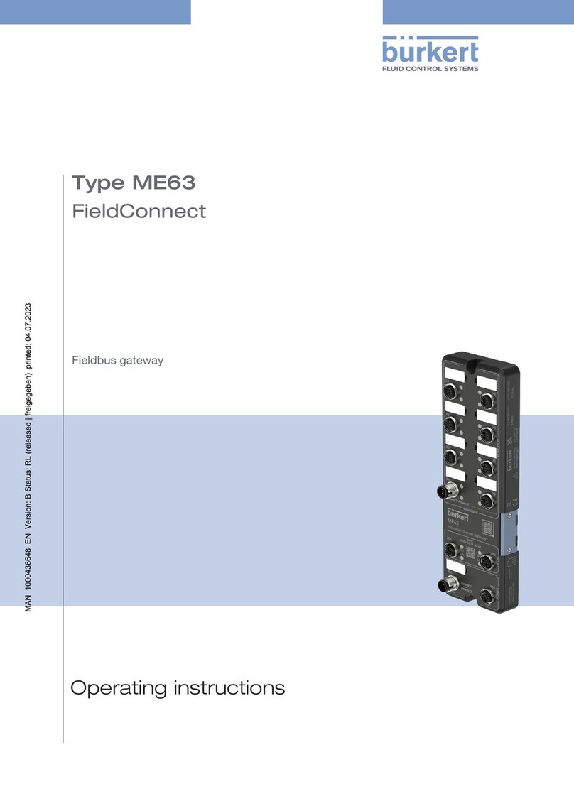
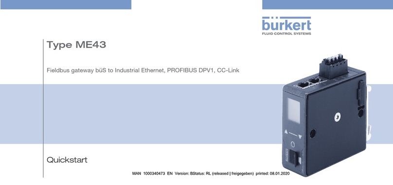
Burkert ME43 User manual

Operating Instructions
Type ME43
Fieldbus gateway büS to Industrial Ethernet for
PROFIBUS DPV1, PROFINET, EtherNet/IP,
EtherCAT, Modbus TCP, CC-Link IE field basic

We reserve the right to make technical changes without notice.
Technische Änderungen vorbehalten.
Sous réserve de modifications techniques.
© Bürkert Werke GmbH & Co. KG, 2017 – 2021
Operating Instructions 2111/04_EUen_00810575 / Original DE

3
Table of conTenTs
1OPERATING INSTRUCTIONS ................................................................................................................6
1.1 Symbols........................................................................................................................................6
1.2 Denitionofterms........................................................................................................................7
2INTENDED USE ......................................................................................................................................7
3BASIC SAFETY INSTRUCTIONS ...........................................................................................................8
4GENERAL NOTES...................................................................................................................................9
4.1 Contactaddresses.......................................................................................................................9
4.2 Warranty .......................................................................................................................................9
4.3 InformationontheInternet..........................................................................................................9
5PRODUCT DESCRIPTION....................................................................................................................10
6TECHNICAL DATA ................................................................................................................................11
6.1 Conformity..................................................................................................................................11
6.2 Standards ...................................................................................................................................11
6.3 Operatingconditions .................................................................................................................11
6.4 Mechanicaldata.........................................................................................................................11
6.5 Electricaldata ............................................................................................................................11
6.6 IndustrialEthernet......................................................................................................................12
6.6.1 PROFINET IO..............................................................................................................12
6.6.2 EtherNet/IP .................................................................................................................12
6.6.3 ModbusTCP...............................................................................................................12
6.6.4 PROFIBUS DPV1........................................................................................................13
6.6.5 EtherCAT.....................................................................................................................13
6.6.6 CC-Link.......................................................................................................................13
6.6.7 OPC UA ......................................................................................................................14
6.7 Typelabel,devicelabelling........................................................................................................14
7INSTALLATION......................................................................................................................................15
7.1 Mountingthedeviceontothestandardrail..............................................................................15
7.2 Electricallyconnectingthedevice ............................................................................................16
TypeME43
English

4
Type ME43
7.3 Establishconnectiontotheeldbus.........................................................................................16
7.3.1 Industrial Ethernet.......................................................................................................16
7.3.2 PROFIBUS version .....................................................................................................17
7.3.3 CC-Link version ..........................................................................................................17
8MICRO SD CARD .................................................................................................................................18
9COMMISSIONING WITH FIELDBUS GATEWAY..................................................................................20
9.1 Operatingelements....................................................................................................................20
9.2 Operationwiththedisplay.........................................................................................................20
9.3 ProtocolsettingsforconnectingthedevicetothePLCnetwork............................................21
9.3.1 Selecting the protocol.................................................................................................21
9.3.2 Enter address..............................................................................................................21
9.4 Settingsonthedisplay ..............................................................................................................22
10 START-UP WITH BÜRKERT COMMUNICATOR ..................................................................................23
10.1 Userinterface.............................................................................................................................23
10.2 ConnectingthedevicetotheBürkertCommunicator .............................................................24
10.3 ProtocolsettingsforconnectingthedevicetothePLCnetwork............................................24
10.3.1 Selecting the protocol.................................................................................................24
10.3.2 Enter PROFIBUS address........................................................................................... 24
10.3.3 Entering CC-Link address ..........................................................................................24
10.3.4 Entering the EtherCAT address (Station Alias)............................................................25
10.3.5 Enter parameters for EthernetNET/IP, PROFINET, Modbus TCP ...............................25
10.4 Conguringtheeldbusgateway .............................................................................................26
10.4.1 Downloadingagatewayconguration ....................................................................... 26
10.4.2 Editingagatewayconguration .................................................................................26
10.4.3 Creatinganewgatewayconguration .......................................................................26
10.5 büSnetwork ...............................................................................................................................38
10.5.1 Set up büS network....................................................................................................38
10.5.2 ConguringthebüSnetwork......................................................................................40
11 START-UP USING A WEB SERVER .....................................................................................................41
11.1 Functionofthewebserver ........................................................................................................41
11.2 DeactivatetothewebserverviaBürkertCommunicator ........................................................41
11.3 Establishingaconnectiontothewebserver............................................................................41
English

5
Type ME43
11.4 Loggingontothewebserver.....................................................................................................42
11.5 Passwords..................................................................................................................................43
11.5.1 Change password.......................................................................................................43
11.5.2 Factory reset of password ..........................................................................................43
11.6 Conguringthedevice...............................................................................................................43
12 OPC UA.................................................................................................................................................44
12.1 Generaldescription....................................................................................................................44
12.2 EstablishconnectionwithOPCUA...........................................................................................44
12.2.1 Settings on the device ................................................................................................44
12.2.2 Settings for the OPC UA client ...................................................................................45
12.3 Servercerticate........................................................................................................................45
13 DISPLAY ELEMENTS ...........................................................................................................................47
13.1 LEDsforindicatingthenetworkconnectiontotheIndustrialEthernet ..................................47
13.2 LEDfordisplayingthedevicestatus ........................................................................................48
14 BÜRKERT COMMUNICATOR MENUS ................................................................................................49
14.1 f(x)conguration ........................................................................................................................49
14.2 “Webserver”and“OPCUA” .....................................................................................................49
14.3 Congurationarea“PROFINET”,“EtherNet/IP”,“ModbusTCP”and“CC-Link” ....................50
14.4 “EtherCAT”congurationarea .................................................................................................51
14.5 Congurationsection“Generalsettings” .................................................................................52
15 REPLACING THE DEVICE....................................................................................................................55
16 TROUBLESHOOTING...........................................................................................................................57
16.1 Descriptionoftheerrorcode ....................................................................................................58
16.2 Statusindicatorsandmeasures................................................................................................62
17 ACCESSORIES.....................................................................................................................................63
18 DISASSEMBLY .....................................................................................................................................64
19 TRANSPORTATION,STORAGE,DISPOSAL........................................................................................65
English

6
Operating instructions
Type ME43
1 OPERATING INSTRUCTIONS
The operating instructions describe the entire life cycle of the device. Keep these instructions ready to hand
at the operation site.
Importantsafetyinformation.
▶Read these instructions carefully.
▶Observe in particular the safety instructions, intended use and operating conditions.
▶Persons who work on the device must read and understand these instructions.
1.1 Symbols
DANGER
Warnsofanimmediatedanger.
▶Failure to observe these instructions will result in death or serious injuries.
WARNING
Warnsofapotentiallyhazardoussituation.
▶Failure to observe these instructions may result in serious injuries or death.
CAUTION
Warnsofapotentialdanger.
▶Failure to observe may result in moderate or minor injuries.
NOTE
Warnsofdamage.
▶Failure to observe these instructions may result in damage to the device or the system.
Indicatesimportantadditionalinformation,tipsandrecommendations.
Referstoinformationintheseoperatinginstructionsorinotherdocumentation.
Designates instructions to avoid danger.
Designates a procedure which you must carry out.
Designates a result.
MENU Symbol for software interface texts.
English

7
Operating instructions
Type ME43
1.2 Denition of terms
Denitionofthetermsusedintheseinstructions.
•Device: the term “Device” stands for the following device types: ME43
•Exarea:the term “Ex area” stands for potentially explosive atmosphere
•Ex approval: the term “Ex approval” stands for approval in the potentially explosive atmosphere
•büS (Bürkert system bus): the term “büS” stands for the communication bus developed by Bürkert, based
on the CANopen protocol.
2 INTENDED USE
Improperuseofthedevicemaybedangeroustopeople,nearbyequipmentandtheenvironment.
TheeldbusgatewayTypeME43isusedasaeldbusconverterfortheprocessvaluesbetweenbüS
participantsandanindustrialEthernetPLC.
TheTypeME43supportstheeldbusprotocolsPROFIBUSDPV1,EtherCAT,PROFINET,EtherNet/IP,
ModbusTCP,CC-LinkaswellasDeviceNetandCANopen.
▶To use the device, observe the permitted data, operating conditions and application conditions. These
specicationscanbefoundinthecontractdocuments,theoperatinginstructionsandonthetypelabel.
▶In the potentially explosive atmosphere, only use devices that are approved for this purpose. These
devicesareidentiedbyaseparateExtypelabel.Beforeuse,notetheinformationontheseparateEx
type label and the Ex additional information or the separate Ex operating Instructions.
Thedevice
▶must not be used outdoors.
▶must not be opened.
▶must only be used in conjunction with third-party devices and components recommended and autho-
rised by Bürkert.
▶must only be used when in perfect condition; always ensure proper storage, transportation, installation
and operation.
▶only as intended.
English

8
Basic safety instructions
Type ME43
3 BASIC SAFETY INSTRUCTIONS
These safety instructions do not take into account any unforeseen circumstances and events which occur
duringinstallation,operationandmaintenance.Theoperatorisresponsibleforobservingthelocation-specic
safety regulations, also with reference to personnel.
Generalhazardoussituations.
To prevent injuries, observe the following:
▶Use the device only when it is in perfect condition and in accordance with the operating instructions.
▶Do not make any changes to the device and do not subject it to mechanical stress.
▶Secure device or system to prevent unintentional activation.
▶Only trained technicians may perform installation and maintenance work.
▶Install the device according to the regulations applicable in the respective country.
▶After an interruption in the power supply, ensure that the process is restarted in a controlled manner.
▶Observe the general rules of technology.
NOTE
Electrostaticallysensitivecomponentsandassemblies.
Thedevicecontainselectroniccomponentsthataresusceptibletotheeectsofelectrostaticdischarging
(ESD).Componentsthatcomeintocontactwithelectrostaticallychargedpersonsorobjectsareatrisk.
Intheworstcasescenario,thesecomponentswillbedestroyedimmediatelyorfailafterstart-up.
▶MeettherequirementsspeciedbyEN61340-5-1tominimiseoravoidthepossibilityofdamagecaused
by a sudden electrostatic discharge.
▶Do not touch electronic components when the supply voltage is connected.
English

9
General notes
Type ME43
4 GENERAL NOTES
4.1 Contact addresses
Germany
Bürkert Fluid Control Systems
Sales Centre
Christian-Bürkert-Str. 13-17
D-74653Ingelngen
Tel.+49(0)7940-10-91111
Fax+49(0)7940-10-91448
E-mail: [email protected]
International
The contact addresses can be found online at:
www.burkert.com
4.2 Warranty
Apreconditionforthewarrantyisthatthedeviceisusedasintendedinconsiderationofthespeciedoper-
ating conditions.
4.3 Information on the Internet
Operating instructions and data sheets for the Bürkert products can be found on the Internet at:
www.burkert.com
English

10
Product description
Type ME43
5 PRODUCT DESCRIPTION
TheeldbusgatewaytypeME43isusedasaeldbusconverterbetweenbüSandIndustrialEthernet.
Applicationrange:
Exchangeprocessvaluesbetweenparticipantsofeldbus1andeldbus2.
Device type Fieldbus 1 Fieldbus 2
ME43 büS PROFINET
ME43 büS EtherNet/IP
ME43 büS ModbusTCP
ME43 büS PROFIBUS DPV1
ME43 büS CC-LINKIEeldbasic
ME43 büS EtherCAT
Table 1: Application area Type ME43
TheBürkertCommunicatorsoftwareisrequiredtoconguretheeldbusgateway.TheBürkert
Communicator software can be downloaded free of charge from the Bürkert website. In addition to
the software, the USB-büS interface set 1 – which is available as an accessory – is required. See
chapter “17 Accessories”.
English

11
Technical data
Type ME43
6 TECHNICAL DATA
6.1 Conformity
ThedeviceconformstotheEUdirectivesaspertheEUDeclarationofConformity(ifapplicable).
6.2 Standards
Theappliedstandards,whichareusedtodemonstrateconformitywiththedirectives,arelistedintheEUtype
examinationcerticateand/ortheEUDeclarationofConformity(ifapplicable).
6.3 Operating conditions
NOTE
Malfunctionduetoheatandheavyfrost.
▶Donotusethedeviceoutsidethespeciedambienttemperature.
Ambienttemperature –20…+60°C
Altitude Upto2000mabovesealevel
6.4 Mechanical data
Dimensions See data sheet for type ME43
Housing material Polycarbonate
6.5 Electrical data
Supplyvoltage: 24V ±10%–residualripple10%
Powerconsumption: <2W
Degree of protection: IP 20 to EN 60529 / IEC 60529 (only with correctly connected cables or
plugsandsockets)veriedbyBürkert,notevaluatedbyUL
Protection class: 3 according to DIN EN 61140 (VDE 0140)
Interfaces 1 spring-loaded terminal, 5-pin for supply voltage and büS connection
PROFIBUS version : 1 push-in connector D-Sub, 9-pin
CC-LINK variant: 1 push-in connector, D-Sub, 9-pin
Industrial Ethernet version: 2 sockets for RJ45 push-in connector
ULdevices: LimitedEnergyCircuit(LEC)accordingtoUL/IEC61010-1
LimitedPowerSource(LPS)accordingtoUL/IEC60950
SELV / PELV with UL Recognized Overcurrent Protection,
designaccordingtoUL/IEC61010-1Table18
NECClass2powersource
English

12
Technical data
Type ME43
6.6 Industrial Ethernet
6.6.1 PROFINET IO
Topology recognition LLDP, SNMP V1, MIB2, Physical Device
Minimum cycle time 10ms
IRT not supported
MRP media redundancy MRP client is supported
Other supported functions DCP, VLAN Priority Tagging, Shared Device
Transmission speed 100MBit/s
Data transport layer Ethernet II, IEEE 802.3
PROFINETIOspecication V2.3
(AR) Application Relations The device can simultaneously process up to 2
IO-ARs, 1 Supervisor AR and 1 Supervisor-DA AR.
6.6.2 EtherNet/IP
Pre-denedstandardobjects Identity Object (0x01)
Message Router Object (0x02)
Assembly Object (0x04)
Connection Manager (0x06)
DLR Object (0x47)
QoS Object (0x48)
TCP/IP Interface Object (0xF5)
Ethernet Link Object (0xF6)
DHCP supported
BOOTP supported
Transmission speed 10and100MBit/s
Duplex modes Half duplex, full duplex, auto-negotiation
MDI modes MDI, MDI-X, Auto-MDIX
Data transport layer Ethernet II, IEEE 802.3
AddressConictDetection(ACD) supported
DLR (ring topology) supported
Integrated switch supported
CIP reset service Identity Object Reset Service types 0 and 1
6.6.3 ModbusTCP
Modbus function codes 1, 2, 3, 4, 6, 15, 16, 23
Operation mode Message mode: Server
Transmission speed 10and100MBit/s
Data transport layer Ethernet II, IEEE 802.3
English

13
Technical data
Type ME43
6.6.4 PROFIBUS DPV1
Acyclic communication DPV1Class1Read/Write
DPV1Class2Read/Write/DataTransport
Transmission speed Fixed values from 9.6 kbit/s to 12 Mbit/s
Autodetect mode is supported
Maximum size of the transferred data Input data: 244 Byte
Outputdata:244Byte
6.6.5 EtherCAT
Maximum quantity of cyclical input and output data 512 Bytes
Maximum quantity of cyclical input data 1024 Bytes
Maximum quantity of cyclical output data 1024 Bytes
Acyclic communication (CoE) SDO
SDO Master-Slave
Type Complex Slave
FMMUs 8
Sync Managers 4
Transmission speed 100MBit/s
Data transport layer Ethernet II, IEEE 802.3
6.6.6 CC-Link
Supported protocols CC-Link-Version 2.0
CC-Link-Version 1.11
CC-Linkversion2.0
Number of stations Up to 4 occupied stations
Maximum quantity of input data 368 Bytes
Maximum quantity of output data 368 Bytes
Input data 112Bytes(RY)and256Bytes(RWw)
Output data 112Bytes(RX)and256Bytes(RWr)
Extended cycles 1, 2, 4, 8
Transmission speeds 156 kBit/s, 625 kBit/s, 2500 kBit/s, 5 MBit/s, 10 MBit/s
CC-Linkversion1.1
Number of stations Up to 4 occupied stations
Maximum quantity of input data 48 Bytes
Maximum quantity of output data 48 Bytes
Input data 4Bytes(RY)and8Bytes(RWw)peroccupiedstation
Output data 4Bytes(RX)and8Bytes(RWr)peroccupiedstation
Transmission speeds 156 kBit/s, 625 kBit/s, 2500 kBit/s, 5 MBit/s, 10 MBit/s
English

14
Technical data
Type ME43
6.6.7 OPC UA
On delivery, the OPC UA server is not enabled.
The OPC UA server runs in the background with the following protocols:
•PROFINET IO
•EtherNet/IP
•ModbusTCP
The function for enabling or disabling the OPS UA server can be set in Bürkert Communicator:
OPC UA>Parameters>ActivateOPCUA
Figure 1: Activate OPC UA
After activating the OPC UA, other server settings will become visible. Note chapter “12” on this topic.
6.7 Type label, device labelling
Data matrix code
(link for further information on the
device)
Identicationnumberofdevice
Serial number
Manufacture code
Permitted ambient temperature
range
Type
Supply voltage,
nominal power,
degree of protection
CE mark
Tamb -20 °C...+60 °C
24 V | 2 W | IP20
Made in Germany
74653 Ingelngen
ID: 00307390
Type: ME43
S/N: 001001
W1XXXX
Figure 2: Description of type label and device labelling
English

15
Installation
Type ME43
7 INSTALLATION
WARNING
Riskofinjuryduetoimproperinstallation.
▶Installation may be carried out by authorised technicians only and with the appropriate tools.
▶Secure the system against unintentional activation.
▶Following installation, ensure a controlled restart.
7.1 Mounting the device onto the standard rail
→Hook the device into the lower guide of the standard rail.
→Push the device upward while tilting it to the left and lock
it into the upper guide of the standard rail.
Forbetteraccessibilitytotheconnections,theunitcanbemountedrotatedby180°ifnecessary.
→Loosen the screw.
→Turnthestandardrailclipby180°.
→Tighten locking screw with 2 Nm.
Figure 3: Mounting the device onto the standard rail
English

16
Installation
Type ME43
7.2 Electrically connecting the device
→Connect 5-pin spring clamp terminal according to the assignment.
Assignment5-pinspringclampterminal
Plugview Terminalcolour Description
Red Supply voltage 24 V
White CAN_H (büS connection)
Green Shielding
Blue CAN_L (büS connection)
Black GND
Table 2: Assignment 5-pin spring clamp terminal
7.3 Establish connection to the eldbus
7.3.1 Industrial Ethernet
→Plug the Ethernet cables into the sockets of interfaces X1 and X2.
The interfaces X1 and X2 for RJ45 push-in connectors are equivalent.
AssignmentinterfaceX1andX2
1
2
3
4
5
6
7
8
Pin Plugconguration
1 TX+
2 TX–
3 RX+
4 Not used
5 Not used
6 RX–
7 Not used
8 Not used
Figure 4: Assignment of interfaces X1 and X2; connection to eldbus
NOTE
Toensureelectromagneticcompatibility(EMC).
▶Only use shielded Ethernet cables.
▶To ground the cable shield, connect the Ethernet cables of all participants to the standard rail via the
backplane.
→Connect supply voltage.
English

17
Installation
Type ME43
7.3.2 PROFIBUS version
RemoveD-Sub,9-pinpush-inconnector.
D-Sub,9-pin Pin Signal Function Connection
1
2
6
3
7
4
8
5
9
1 Not used
2 Not used
3 RxD/TxD-P Data line P (B conductor) Duty
4 CNTR-P Repeater directional control optional
5 DGND Ground for bus terminating resistor optional
6 VP +5 V supply, bus terminating resistor optional
7 Not used Not used
8 RxD/TxD-N Data line N (A line) Duty
9 Not used
Figure 5: PROFIBUS, assignment of D-Sub 9-pin plug connector
7.3.3 CC-Link version
RemoveD-Sub,9-pinpush-inconnector.
D-Sub,9-pin Pin Signal Function Connection
1
2
6
3
7
4
8
5
9
1 Not used
2 Not used
3DA Data line A Duty
4 DG Data ground Duty
5 Not used
6 Not used
7 Not used
8 DB Data line B Duty
9 Not used
Figure 6: CC-Link, pin assignment D-Sub 9-pin connector
English

18
Micro SD card
Type ME43
8 MICRO SD CARD
ThemicroSDcardcanbeusedtostoredevice-specicvaluesandusersettingsandtransferthemtoanother
device.
ThemicroSDcardisnotsuitableforbackups.IfthemicroSDcardofthedeviceisre-insertedatalater
stage, the data last saved are not restored. The function of the micro SD card is limited to data exchange.
Note!
By resetting the device to the factory settings, the data saved on the SD card are also reset.
A newly created micro SD card is checked for the presence of existing data when the device is re-started. This
data will be transferred or overwritten accordingly:
•The micro SD card does not contain any data.
Theexistingdevice-specicvaluesaresavedtothemicroSDcard.
•The micro SD card contains data compatible with the device.
ThedataonthemicroSDcardaretransferredbythedevice.Theexistingdevice-specicvaluesare
saved to the micro SD card.
•The micro SD card contains data that are not compatible with the device.
ThedeviceoverwritesthedataonthemicroSDcardwithitsowndevice-specicvaluesanduser
settings.
NOTE
ThemicroSDcardusedisaspecialindustrialversionthatoersadditionaldurabilityand
temperature-resistance.
►Do not use a standard micro SD card for the device. Only purchase the micro SD card for the device
from your Bürkert sales department.
Bonnet
Card slot for micro SD card
Figure 7: Change micro SD card; ME43 eldbus gateway
NOTE
RemovingtheSDcardwhilethepowersupplyisoncanleadtodatalossanddamagetothecard.
►Do not remove the SD card while the device is connected to the supply voltage.
The SD card can be inserted while the device is connected to the supply voltage.
A restart is required to ensure that the device detects the SD card.
English

19
Micro SD card
Type ME43
Removing the micro SD card:
→Pull the bonnet carefully out of the recess.
→Turn the bonnet away from the top left.
→To unlock, press on the edge of the engaged micro SD card.
→Remove the micro SD card.
Insert the micro SD card into the replacement device:
Observe the direction of insertion when inserting the card.
→Slide the micro SD card into the card slot.
Make sure that the micro SD card locks into position.
→Close card slot with bonnet.
8.1 Conguration provider
SpecifywhetherthedevicewillcompilethecongurationfromotherdevicesinthebüSnetwork(cong
clients) and saves it on the SD card.
This function is only possible if an SD card is present in the device.
English

20
Commissioning with eldbus gateway
Type ME43
9 COMMISSIONING WITH FIELDBUS GATEWAY
9.1 Operating elements
Arrow key, down arrow
Arrow key, up arrow
Menu button
Card slot for micro SD card
Bonnet
Figure 8: Overview of the operating elements
9.2 Operation with the display
The display is operated with the two arrow keys and the round menu key.
Openthemainmenu:
→Press menu button twice.
Returningfromamenu:
→Use the arrow keys Back or Discard or Savetoselectandconrmwiththemenukey.
Eectoftheselection:
Back Return to the next, higher menu level.
Discard Discards unsaved settings and returns to the next, higher menu level.
Save Save changed settings and return to the next, higher menu level.
Descriptionofbuttons:
Element Description
Down arrow
key
Scroll down in the menu
Reduce numerical values. Press and hold the arrow key to scroll quickly
Up arrow key Scroll up in the menu
Raise numerical values. Press and hold the arrow key to scroll quickly
Menu button Open main menu (press menu button twice)
Conrmselection
Conrminput
Table 3: Description of buttons
English
Other manuals for ME43
2
Table of contents
Other Burkert Gateway manuals