Burkert FreeLINE 8645 Wiring diagram

FreeLINE
Description for the replacement of modules within the valve
terminal
Beschreibung für den Austausch von Modulen innerhalb der
Ventilinsel
Description de l‘échange de modules dans îlot de vannes

We reserve the right to make technical changes without notice.
Technische Änderungen vorbehalten.
Sous resérve de modification techniques.
© 2008 Bürkert Werke GmbH & Co. KG
Operating Instructions 0811/00_EU-ML_00805841

Co n t e n t s
english

The supplementary instructions describe the extension of a valve terminal FreeLINE Type 8645. Keep these instruc-
tions in a location, which is easily accessible to every user, and make these instructions available to every new owner
of the device.
Please read the supplementary instructions thoroughly.
Follow the safety instructions!•
Failure to observe the warning may result in a fatal or serious injury.•
Failure to observe the warning may result in serious injuries or death. •
Failure to observe this warning may result in a medium or minor injury. •
Failure to observe the warning may result in damage to the device or the equipment. •
indicates important additional information, tips and recommendations which are important for your safety
and the flawless functioning of the device.
refers to information in these operating instructions or in other documentation.
designates a procedure which you must carry out.
→
english

If you are unsure, please contact your Bürkert Sales Center.
Contact address:
Bürkert Fluid Control System
Sales Center
Chr.-Bürkert-Str. 13-17
D-74653 Ingelfingen
Tel. + 49 (0) 7940 - 10 91 111
Fax + 49 (0) 7940 - 10 91 448
E-mail: [email protected]
Contact addresses can be found on the final pages of these operating instructions.
And also on the internet at:
www.buerkert.com Bürkert Company Locations
The operating instructions and data sheets for Type 8645 can be found on the Internet at:
www.burkert.com Documentation manuals / data sheets Type 8645
english

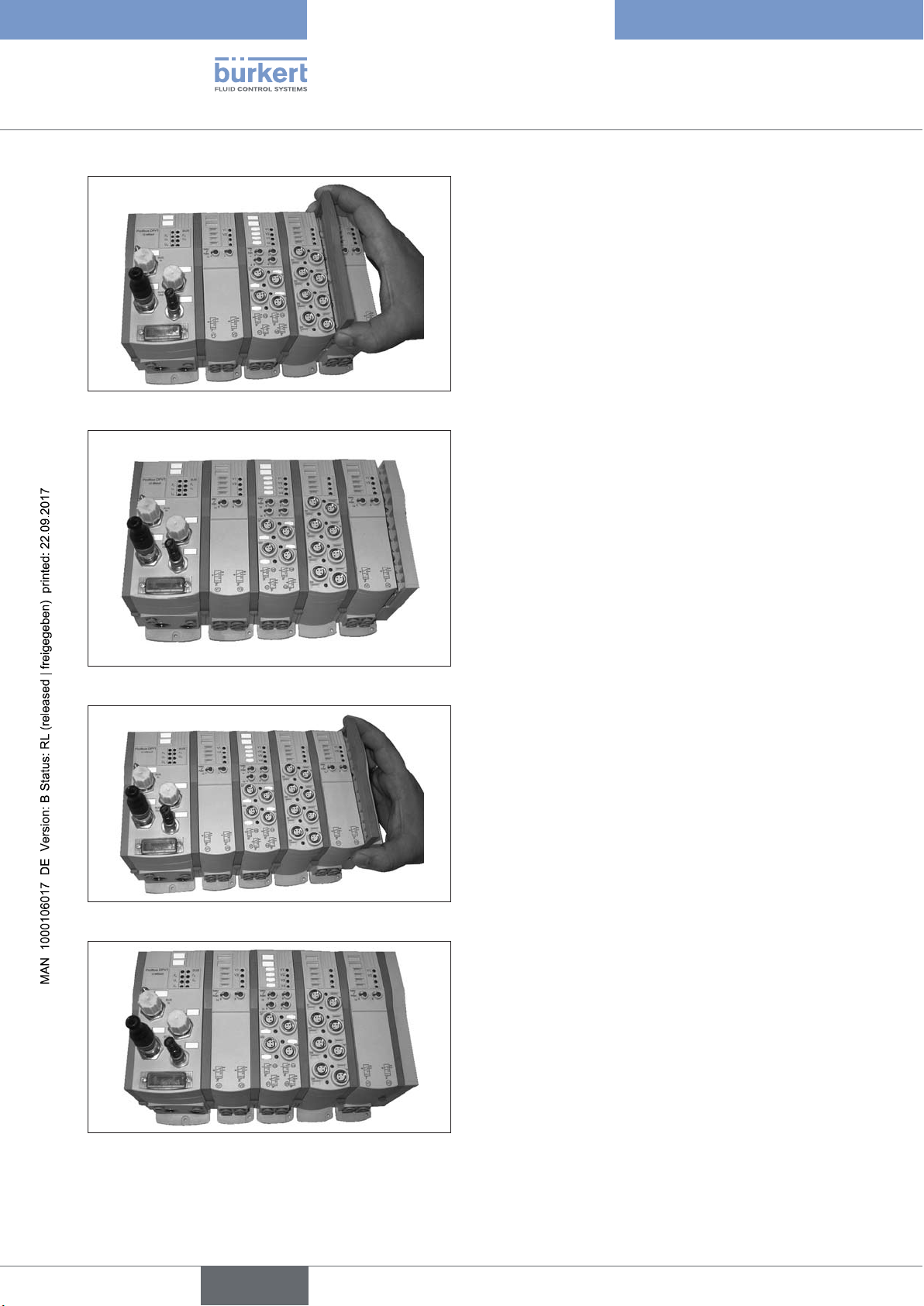
The supplementary instructions describe the replacement of modules within a valve terminal Type 8645 as well as
its extension by additional modules. Also follow the overall operating instructions and the Quickstart for handling
the complete device
There is a serious risk of injury when reaching into the equipment.
Turn off the pressure and release the pressure in the pipes before loosening pipes and valves!•
There is a serious risk of injury when reaching into the equipment.
Before starting work, always switch off the power supply and safeguard to prevent re-activation!•
Observe applicable accident prevention and safety regulations for electrical equipment!•
Improper assembly may result in injuries as well as damage to the device and the area around it.
This work may be carried out by authorised technicians only and with the appropriate tools!•
Hazardous situations may arise due to unintentional activation of the system.
Take appropriate measures to prevent the equipment from being unintentionally activated.•
The device contains electronic components, which react sensitively to electrostatic discharge (ESD). Contact
with electrostatically charged persons or objects is hazardous to these components. In the worst case scenario,
they will be destroyed immediately or will fail after start-up.
Observe the requirements in accordance with EN 100 015 – -1 to minimise or avoid the possibility of dam-•
age caused by sudden electrostatic discharge!
Also, ensure that you do not touch electronic components when the power supply voltage is present!•
english

1
To expand the FreeLINE valve terminal, first detach
the blue connecting bracket.
Using the two projecting lugs, pull up the blue
→
connecting bracket 1 and remove.
Attaching the connecting bracketFig. 1:
Pulling on one side may damage the locking bracket!
Using a screwdriver, release the 3 locking pins by
→
turning them through 90°.
In the released position the slots in the locking pins
are horizontal. The locking pins project over the
contact surface of the connecting bracket.
Release locking pinsFig. 2:
Supporting the snapping out of the locking pinsFig. 3:
By applying gentle lateral pressure to the exposed side areas of the valve terminal in the vicinity of the cor-
responding locking pins, they can be supported as they are snapped out.
english

By snapping out the three locking pins, the following
module is released and can be removed without
difficulty.
Releasing the following moduleFig. 4:
Remove the cover module parallel to the side.
→
The interface to expand the valve terminal is now
free.
Removing the cover moduleFig. 5:
If more modules are to be removed, repeat steps
→
1-3.
Ensure that an FE rail on the upper side of the ter-
minal is detached. Also the modules to be removed
must be detached from the wall or top hat rail.
Removing more modulesFig. 6:
english

Before adding new modules, first check that the
→
O-rings and seals are correctly positioned.
Then grease the O-rings and seals, both on
→
the pneumatic channels and on the electrical
connections.
Checking O-rings and sealsFig. 7:
Connect additional module to the valve terminal
→
by pushing it on parallel and pressing it into
position.
Ensure that the seals and plug-in contacts are not
damaged.
Attaching additional moduleFig. 8:
Connect added modules to the existing valve
→
terminal by pressing and then turning the three
locking through 90°.
The depression of the locking pins can be facili-
→
tated by pressing the module onto the existing
valve terminal. The slot is vertical.
Then attach the added modules to the wall or top
→
hat rail.
Securing added modulesFig. 9:
english

Push the blue locking bracket over the desig-
→
nated guides.
Ensure that the connecting bracket is inserted neatly
into the guides and is pushed down .
To do this, support the bracket by gripping both
→
lugs.
Attaching the connecting bracketFig. 10:
If more modules are to be added, repeat steps
→
5 – 8.
In doing so, note the appropriate system limits. To
close the valve terminal, attach the cover module
which fits the corresponding head module.
Attach cover module by pressing parallel on the
→
valve terminal.
Ensure that O-rings, seals and electrical interface are
not damaged.
Attaching more modulesFig. 11:
Lock locking pins according to Step 7 and push
→
down blue connecting bracket according to Step
8.
Re-attach FE rails.
→
Connect additional modules accordingly to the →
FE contact.
Attaching the connecting bracketFig. 12:
The valve terminal is ready for use again!
Valve terminal ready for useFig. 13:
english

Aid when releasing the locking pinsFig. 14:
If the locking pins cannot be released, they can be released from the back of the modules using a
screwdriver.
To do this, press a small screwdriver blade onto the corresponding locking pin on the respective module
until the locking pin disengages audibly.
To replace the communications module, first detach
the blue connecting bracket.
Using the two projecting lugs, pull up blue con-
→
necting bracket and remove from the
interface to the function modules.
Attaching the connecting bracketFig. 15:
Pulling on one side may damage the connecting bracket!
english

Detach any FE rails from the back of the valve
→
terminal.
Detach the module to be replaced from the wall
→
or top hat rail.
Then release and disengage the 3 locking pins by
→
turning them through 90°.
In the released position the slots in the locking pins
are horizontal. The locking pins project over the
contact surface of the connecting bracket.
Releasing the locking pinsFig. 16:
By applying gentle lateral pressure to the exposed side areas of the valve terminal in the vicinity of the cor-
responding locking pins, they can be supported as they are snapped out.
If the modules are removed without disengaging the locking pins, the modules may be damaged.
By snapping out the three locking pins, the head
module is released from the valve terminal and can
be removed without difficulty.
To do this, remove the head module parallel from
→
the side of the terminal.
Removing the head moduleFig. 17:
To attach the new head module, proceed in reverse
sequence.
First grease the seals and O-rings on the module.
→
Then press the module onto the side of the valve →
block.
Ensure that O-rings, seals and electrical plug-and-
socket connections are not damaged.
Attaching the head moduleFig. 18:
english

Connect added modules to the existing valve
→
terminal by pressing and then turning the three
locking through 90°.
The depression of the locking pins can be facili-
tated by pressing the module onto the existing valve
terminal.
The slot is vertical.
→
Attaching more modulesFig. 19:
Push the blue locking bracket over the desig-
→
nated guides.
Ensure that the connecting bracket is inserted neatly
into the guides and is pushed down parallel.
To do this, support the bracket by gripping both
→
lugs and push all the way down.
Attaching the locking bracketFig. 20:
E-rails must be re-attached.
→
Connect additional modules accordingly to the →
FE contact.
The valve terminal is ready for use again.
Remember that any address setting on the head
module must be adjusted to the original state.
To do this, open the window on the corre-
→
sponding head module and, using the rotary
encoding switch, set the corresponding bus
address.
Valve terminal ready for useFig. 21:
english

english

In h a l t
deutsch

Die Ergänzungsanleitung beschreibt die Erweiterung einer Ventilinsel FreeLINE Typ 8645. Bewahren Sie diese
Anleitung so auf, dass sie für jeden Benutzer gut zugänglich ist und jedem neuen Eigentümer des Gerätes wieder
zur Verfügung steht.
Lesen Sie die Ergänzungsanleitung sorgfältig.
Beachten Sie die Sicherheitshinweise!•
Bei Nichtbeachtung sind Tod oder schwere Verletzungen die Folge.•
Bei Nichtbeachtung drohen schwere Verletzungen oder Tod. •
Nichtbeachtung kann mittelschwere oder leichte Verletzungen zur Folge haben. •
Bei Nichtbeachtung kann das Gerät oder die Anlage beschädigt werden. •
bezeichnet wichtige Zusatzinformationen, Tipps und Empfehlungen, die für Ihre Sicherheit und die ein-
wandfreie Funktion des Gerätes wichtig sind.
verweist auf Informationen in dieser Bedienungsanleitung oder in anderen Dokumentationen.
markiert einen Arbeitsschritt, den Sie ausführen müssen.
→
deutsch

Wenden Sie sich bei Unklarheiten oder Fragen an Ihre jeweilige Vertriebsniederlassung.
Kontaktadresse:
Bürkert Fluid Control System
Sales Center
Chr.-Bürkert-Str. 13-17
D-74653 Ingelfingen
Tel. + 49 (0) 7940 - 10 91 111
Fax + 49 (0) 7940 - 10 91 448
E-mail: [email protected]
Die Kontaktadressen finden Sie auf den letzten Seiten dieser Bedienungsanleitung.
Außerdem im Internet unter:
www.buerkert.com Bürkert Company Locations
Bedienungsanleitungen und Datenblätter zum Typ 8645 finden Sie im Internet unter:
www.buerkert.de Dokumentationen Datenblatt/Bedienungsanleitung Typ 8645
deutsch

Die Ergänzungsanleitung beschreibt den Austausch von Modulen innerhalb einer Ventilinsel Typ 8645 sowie deren
Erweiterung um zusätzlich Module. Beachten Sie zur Handhabung des Komplettgerätes auch die Gesamtbedie-
nungsanleitung und das Quickstart.
Bei Eingriffen in die Anlage besteht akute Verletzungsgefahr.
Schalten Sie den Druck ab und entlüften Sie die Leitungen, bevor Sie Leitungen und Ventile lösen!•
Bei Eingriffen in die Anlage besteht akute Verletzungsgefahr.
Schalten Sie vor Beginn der Arbeiten in jedem Fall die Spannung ab und sichern Sie diese vor •
Wiedereinschalten!
Beachten Sie die geltenden Unfallverhütungs- und Sicherheitsbestimmungen für elektrische Geräte!•
Durch nicht sachgemäße Montagearbeiten können zu Verletzungen, sowie Schäden am Gerät und seiner
Umgebung führen.
Diese Arbeiten dürfen nur durch autorisiertes Fachpersonal und mit geeignetem Werkzeug durchgeführt •
werden!
Durch unbeabsichtigtes Betätigen der Anlage können Gefahrensituationen entstehen.
Verhindern Sie durch geeignete Maßnahmen, dass die Anlage unbeabsichtigt betätigt werden kann.•
Das Gerät enthält elektronische Bauelemente, die gegen elektrostatische Entladung (ESD) empfindlich
reagieren. Berührung mit elektrostatisch aufgeladenen Personen oder Gegenständen gefährdet diese Bauele-
mente. Im schlimmsten Fall werden sie sofort zerstört oder fallen nach der Inbetriebnahme aus.
Beachten Sie die Anforderungen nach EN 100 015-1, um die Möglichkeit eines Schadens durch schlagar-•
tige elektrostatische Entladung zu minimieren bzw. zu vermeiden!
Achten Sie ebenso darauf, dass Sie elektronische Bauelemente nicht bei anliegender Versorgungsspannung •
berühren!
deutsch

1
Zur Erweiterung der Ventilinsel FreeLINE muss
zunächst der blaue Verbindungsbügel gelöst werden.
Blauen Verbindungsbügel 1 mit Hilfe der beiden
→
überstehenden Nasen nach oben
abziehen.
Verbindungsbügel demontierenBild 1:
Ein entsprechendes einseitiges Ziehen kann zur Beschädigung des Verriegelungsbügels führen!
Mit Hilfe eines Schraubendrehers die 3 Verriege-
→
lungsbolzen durch Drehen um 90°
entriegeln.
In entriegelter Position stehen die Schlitze in den
Verriegelungsbolzen horizontal. Die Verriegelungs-
bolzen stehen über die Auflagefläche des Verbin-
dungsbügels über.
Verriegelungsbolzen entriegelnBild 2:
Herausschnappen der Verriegelungsbolzen unterstützenBild 3:
Durch leichten seitlichen Druck jeweils auf die freiliegenden Seitenflächen der Ventilinsel im Bereich der
entsprechenden Verriegelunsbolzen kann deren Herausschnappen unterstützt werden.
Eine Demontage der Module ohne dass die Verriegelungsbolzen herausgerastet sind, kann zur Beschädigung
der Module führen
deutsch

Durch das Herausschnappen der drei Verriegelungs-
bolzen wird das nachfolgende Modul freigegeben
und kann einfach demontiert werden.
Nachfolgendes Modul freigebenBild 4:
Das Abschlussmodul parallel zur Seite
→
wegziehen.
Damit ist die Schnittstelle zur Erweiterung der Venti-
linsel frei.
Abschlussmodul demontierenBild 5:
Sollen weitere Module demontiert werden, dann
→
die Schritte 1-3 entsprechend wiederholen.
Dabei beachten, dass eine vorhandene FE-Schiene
an der Oberseite der Insel gelöst werden muss.
Ebenso müssen die zu demontierenden Module von
der Wand bzw. Hutschiene gelöst sein.
Weitere Module demontierenBild 6:
deutsch
Other manuals for FreeLINE 8645
1
Table of contents
Languages:
Other Burkert Touch Terminal manuals