C
1 - 17
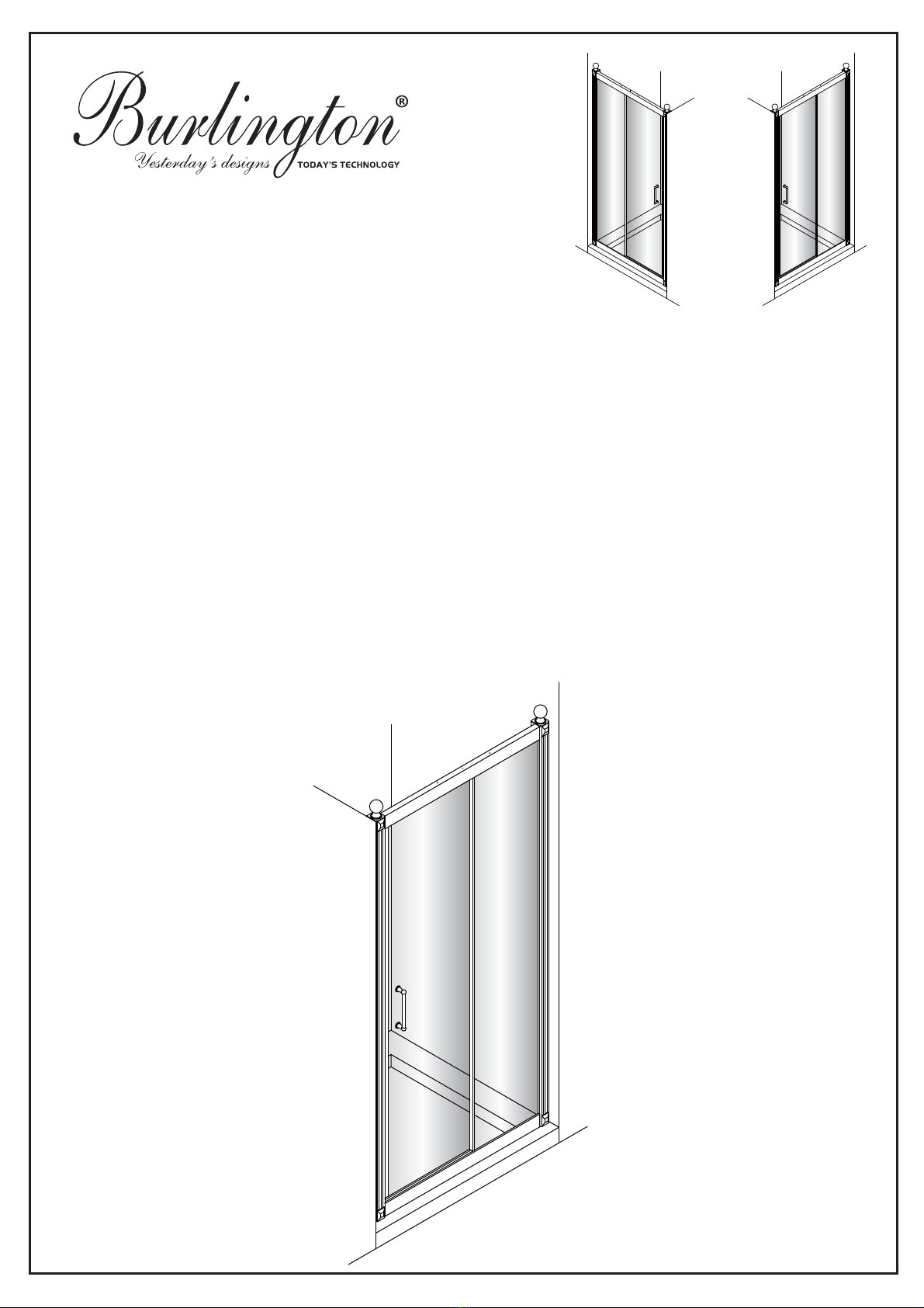
Hinged Door and Inline Panel (Pages 5 - 10)
LH
Ɣ3/($6(5()(5727+(,1',9,'8$/'225$1'6,'(3$1(/,16758&7,216)25&255(&7
,167$//$7,21:,7+7+,6,1/,1(3$1(/
Ɣ&KHFNWKHFRQWHQWVRIWKHSDFNFDUHIXOO\EHIRUHLQVWDOODWLRQ
Ɣ7KHWUD\0867EHLQVWDOOHGOHYHODQGIXOO\VHDOHGWRWKHWLOHV
Ɣ+DQGOHZLWKFDUH,PSDFWVFDQGDPDJHERWKWKHJODVVDQGWKHIUDPH
Ɣ&KHFNIRUDQ\KLGGHQSLSHVRUFDEOHVEHIRUHGULOOLQJKROHVLQWKHZDOO
Ɣ7KHHQFORVXUHLVUHYHUVLEOHGRRUFDQEHHLWKHUOHIWRUULJKWRSHQLQJ
,QWKHUHPDLQGHURIWKLVPDQXDOWKHLOOXVWUDWLRQVZLOORQO\VKRZWKHULJKWKDQGLQVWDOODWLRQ
7KHSDUWVPDUNHG³/+´RU³5+´ZRXOGEHRQO\VXLWDEOHIRUWKHUHODWLYHVKRZHUHQFORVXUH
Ɣ7KHZDOOIL[LQJVVXSSOLHGPD\QRWEHVXLWDEOHIRU\RXULQVWDOODWLRQ<RXPD\QHHGWRVRXUFHDOWHUQDWLYHV
GHSHQGLQJRQWKHFRQVWUXFWLRQRIWKHZDOO\RXDUHIL[LQJWR
&DUHDQG&OHDQLQJ
Ɣ'RQRWXVHVROYHQWVRUDEUDVLYHPDWHULDORUFKHPLFDOVWRFOHDQWKHHQFORVXUH
Ɣ2QO\FOHDQXVLQJVRDS\ZDWHUDQGDVRIWFORWKULQVHWKRURXJKO\DIWHUZDUGV
LH
200 Inline panel - C15
300 Inline panel - C16
400 Inline panel - C17
5+
5+
+LQJHG'RRUDQG,QOLQH3DQHOZLWK6LGH3DQHO3DJHV