Burnham Aquastat IQ Option Card User manual

Aquastat®IQ Option Card, p/n 102720-01, 102717-01
Instruction Sheet
APPLICATION
The Aquastat IQ Option Card provides electronic
temperature sensing in a UL limit-rated control with a
single sensing probe. The Aquastat IQ Option Card
replaces auxiliary high limit Aquastats such as
L4006A, L4008A, L4006E and L4008E.
This product may be applied to either gas or oil fired
steam or hot water boilers equipped with the IQ
Control System. The Aquastat IQ Option card may
be simply “plugged in” to the IQ Option Panel and
only requires sensor and well installation to become
operational.
GENERAL
The Aquastat IQ Option Cards are available in
automatic or manual reset models. Automatic reset
versions automatically reset when temperature return
to safe levels. Manual reset models require user
intervention to reset a temperature condition after the
temperature returns to safe levels.
SPECIFICATIONS
Listings/Approvals
UL353 Limit Controls for both US (UL) and
Canada (CUL)—Component Recognized
UL 1998 Software Safety Standards as a Class 2
device.
Add a Manual Reset Aquastat IQ Option Card,
p/n 102720-01, to the factory mounted
temperature control to be Fully compliant with
CSD-1 requirements for temperature controls in
the US and Canada
Dimensions: 4.5 in. x 1.5 in. (fits onto IQ Option Panel)
Operating temperature: -4°F to 150°F
Shipping and Storage: -40°F to 175°F
Humidity 0 to 95% R.H. Non-condensing
Input ratings: 24 VAC 60 Hz
Reset: Automatic or manual reset modes
Sensor: Dual Sensor, Limit Rated, p/n102295-01
(Honeywell p/n 50001464-004)
with sensor clip 102422-01
Well: p/n 80160456, (Honeywell p/n 123869A),
Spud Size:1/2 inch NPT
Insertion: 3 inches
Insulation: 1-1/2 inches
102715-01-6/09

Aquastat IQ Option Card – Instruction Sheet
Page 2 of 7
INSTALLATION When Installing this Product….
1. Read these instructions carefully. Failure to follow them could damage the product or cause a hazardous
condition. Save instructions for future use.
2. Check the ratings given in the instructions and on the product to make sure the product is suitable for your
application.
3. Installer must be a trained, experienced service technician.
4. After installation is complete, check out product operation as provided in these instructions.
ÌCaution
Electrical Hazard
Disconnect power before beginning installation and wiring. Failure to do so may cause electrical shock or equipment
damage. Wiring must comply with applicable codes, ordinances and regulations.
!
ÌWARNING
Installation must be performed in accordance with all national and local codes and ordinances.
Risk of explosion. Not for use in hazardous locations. Serious injury or death could result.
When installations are complete, check for correct operation of ALL limit and operating controls.
Wire insulation must be rated at 221º F (105º C) or greater, over copper conductors only. Use of other wire or
insulation types could result in fire causing property damage, serious injury, and death.
Hot or pressurized boiler systems can discharge steam and hot water. Cool boiler system to 80º F (27º C) and to
0 psi (0 bar) before servicing. Failure to do so could result in serious burns.
!
ÌCaution
Limit settings are safety parameters and adjusting them incorrectly can have
serious consequences.
!
ÌWARNING
Incorrect adjustment can cause equipment damage or serious injury.
Adjustment of Limit Settings should be done by trained personnel only.
!
ÌImportant
Immersion well must fit sensing element and sensor bulb must rest against
bottom of well.
!

Aquastat IQ Option Card – Instruction Sheet
Page 3 of 7
INSTALLATION (continued)
Sensor clip
Sensor clip
installed
Sensor Installation Diagrams
Well and Sensor Installation
1. Turn off all power and drain the boiler.
2. Install sensor with well that was provided with the IQ Option Card. When using an existing well ensure that the
well specifications (Spud Size:1/2 inch NPT, Insertion depth: 3 inches & Insulation: 1-1/2 inches) match the
supplied well and will accommodate the supplied sensor clip.
3. Prepare a properly sized and threaded tapping near the boiler supply water outlet. Choose a location (or existing
tappings) that allows the boiler water to circulate freely over the well.
4. Sparingly coat the well threads with pipe dope.
5. Install the well in the boiler tapping and tighten securely.
6. Refill boiler and check for water leakage.
7. Insert the sensor element into the well until it bottoms. See Sensor Installation diagram above for details
8. Insert sensor clip to hold the sensor against the bottom of the well.
9. Rout sensor wire and connect to Aquastat IQ Option Card
10. Turn power ON.
11. Set High Limit and High Limit Differential (see User Interface Section of this manual)
IMPORTANT
Best thermal response is obtained with a well that snugly fits the sensor. Insert the sensor until it rests against the
bottom of the well. Use a well of correct length and install sensor clip. If the well is not a snug fit on the sensor, use the
heat-conductive compound, p/n 8056220, (Honeywell p/n 120650)
IQ Option Card Installation
1. Turn off power to the boiler before installing
the option card
2. Select an unoccupied IQ Option Panel slot
and carefully insert pins on the IQ Option
Panel header into the connector on the
bottom of the option card.
NOTE
Use caution not to bend the pins.
3. Gently push the option card into the IQ
Option Panel option slot until it locks into
place. The IQ Option Panel will automatically
recognize the option card and establish
communication.
Insert IQ Option Card into selected slot

Aquastat IQ Option Card – Instruction Sheet
Page 4 of 7
INSTALLATION (continued)
Checkout
Check to make certain that the Aquastat IQ Option Card has been installed and adjusted to the proper settings. Put
the system into operation and observe the action of the device through several cycles to make certain that it provides
proper control of the system as described in the Operations section. Further adjustments can be made to meet more
exact comfort requirements.
Operation
Automatic Reset Aquastat IQ Option Cards:
1. When checking out the system, adjust the control point low enough so the temperature of the controlled medium
reaches the high limit setting and the burner shuts off. When the temperature of the controlled medium drops to the
high limit setting minus differential the system should be operative again.
2. Reset control to proper high limit setting.
Manual Reset Aquastat IQ Option Cards:
1. When checking out the system, adjust the control point low enough so the temperature of the controlled medium
reaches the high limit setting, the burner shuts off, and the Aquastat Controller “locks out”. When the temperature
of the controlled medium drops to the high limit setting minus differential, activate the manual reset button (refer to
“How To Reset The Aquastat” below for reset procedure) and the system should be operative again.
2. Reset control to proper high limit setting.
USER INTERFACE
Aquastat IQ Option Card Features
LED Description
Flashing Red High Temperature, Lockout and manual
reset required or fault indicator
Green TX Enviracom® communication indicator

Aquastat IQ Option Card – Instruction Sheet
Page 5 of 7
USER INTERFACE (continued)
Using IQ Option Panel Display
The IQ Option Panel display along with Up , Down ,
and “ ” keys are used to view and adjust IQ Option Card
settings. Please note that these keys look similar to the
keys on the IQ Boiler Control but are in a different
orientation, and they perform different functions.
Selecting IQ Option Card
To access an IQ Option Card:
1. Press the “ ” key. The display will go from “OCP” to
C1, C2 and C3 (when cards are installed) to provide
access to each of the card slots and the card plugged
into that slot.
2. Press either the Up or Down keys when the
display shows the card number where the Aquastat
card is installed. For example, if the Aquastat card is
installed in slot one, press the Up or Down keys
when “C1” is displayed.
This will switch the display to show the IQ Option Card
View Mode.
Showing View Mode Options
In view mode the user may look at (but not change) status
and temperature readings. To view option card
information:
1. Press and release the “ ” button. The following table
shows the items that will be displayed in view mode:
View Mode Options
HL High limit setting of Aquastat
DF High limit differential of Aquastat
St Sensor temperature of Aquastat
err
Error (Followed By Error No.)
18 Internal Fault
119 Sensor Failure
25 Lockout, manual reset required
(refer to Trouble Shooting Section for
more information)
Bac Return to OCP Option Card Select Menu
Each setting will alternately flash between the relevant
display code, its corresponding value and units. For
example, when the “ ” key is pressed until “st” is
displayed, it will then flash a display a number (such as
“180”) and followed by either “F” (or “C”). This indicates
that the sensed temperature is 180°F. Other view mode
items display the information in a similar fashion.
Unit Display
OR
Sample
Display
1 sec 1 sec
1 sec
Please note that in view mode to hold the display on the
value the user can press and hold either the Up or
Down keys and the value will be continuously shown.
This may be helpful in watching a value “live”.
To exit view mode and return to the IQ Option Panel
menu:
1. Press the “I” button to select the “bac" menu item.
2. Press either the Up or Down keys to exit the card
menu.
“” Ke
y
IQ Option
Panel Display
“Up” Ke
y
“Down” Ke
y
IQ Option Panel User Interface
C1 C2 C3
IQ O
p
tion Panel Card Slot

Aquastat IQ Option Card – Instruction Sheet
Page 6 of 7
USER INTERFACE (continued)
Entering Adjustment Mode
In Adjustment Mode, the user can adjust the High Limit or
Differential, change measurement units or reset a high
temperature condition for Manual Reset models. To enter
adjustment mode:
1. Press and hold the Up , Down ,and “ ” keys
simultaneously for three (3) seconds while the display
is in the Aquastat card View Mode. While holding the
buttons the display will change to an Adjustment
mode label signifying to the user that installer mode
has been entered. This procedure is intended to
discourage unauthorized or accidental changes to
parameter settings.
2. After entering Adjustment Mode, Press the “ ” key to
view the item to be adjusted.
3. Press the Up or Down keys to adjust the
displayed setpoint to the desired value.
4. Exit adjustment mode by one of the following means:
a. Press the “ ” key until “bac” option is
displayed and press either Up or Down
keys
b. Press and Hold the Up , Down ,and “ ”
keys until the first item of view mode is
shown.
c. If no keys are pressed, after five (5) minutes
the display will automatically return to the
view mode.
5. Once in view mode press the “ ” key until “bac” option
is displayed and press either Up or Down keys to
return to the IQ Option Panel Display.
How To Reset The Aquastat
To Reset the Manual Reset Type Aquastat Card:
1. Make sure that the temperature has returned to
normal.
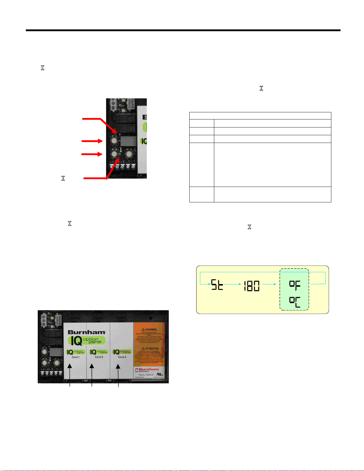
2. Press “ ” key until the Aquastat card slot number is
displayed (C1, C2 or C3).
3. Press the Up or Down keys to enter the card's
view mode
4. Press and Hold the Up , Down ,and “ ” keys
simultaneously for three (3) seconds, Adjustment
Mode items will be shown
5. Press “ ” until the Reset (rst) Pushbutton is shown.
6. Press the Up or Down keys to turn Reset “on”
NOTE: Resetting lockout only applies to Manual Reset
Models.
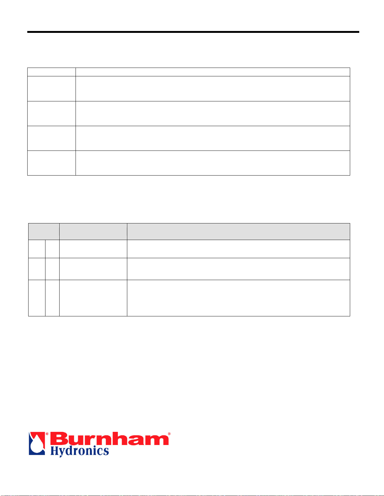
The following table shows adjustable items.
Adjustment Mode Options
Display Factory
Default Range Definition
HL_ 200 130-220 Adjust high limit setting of Aquastat
15 5-30 Auto Reset type IQ Option Card, adjustable High Limit differential
DF_ 5 - Manual Reset type IQ Option Card, fixed High Limit differential
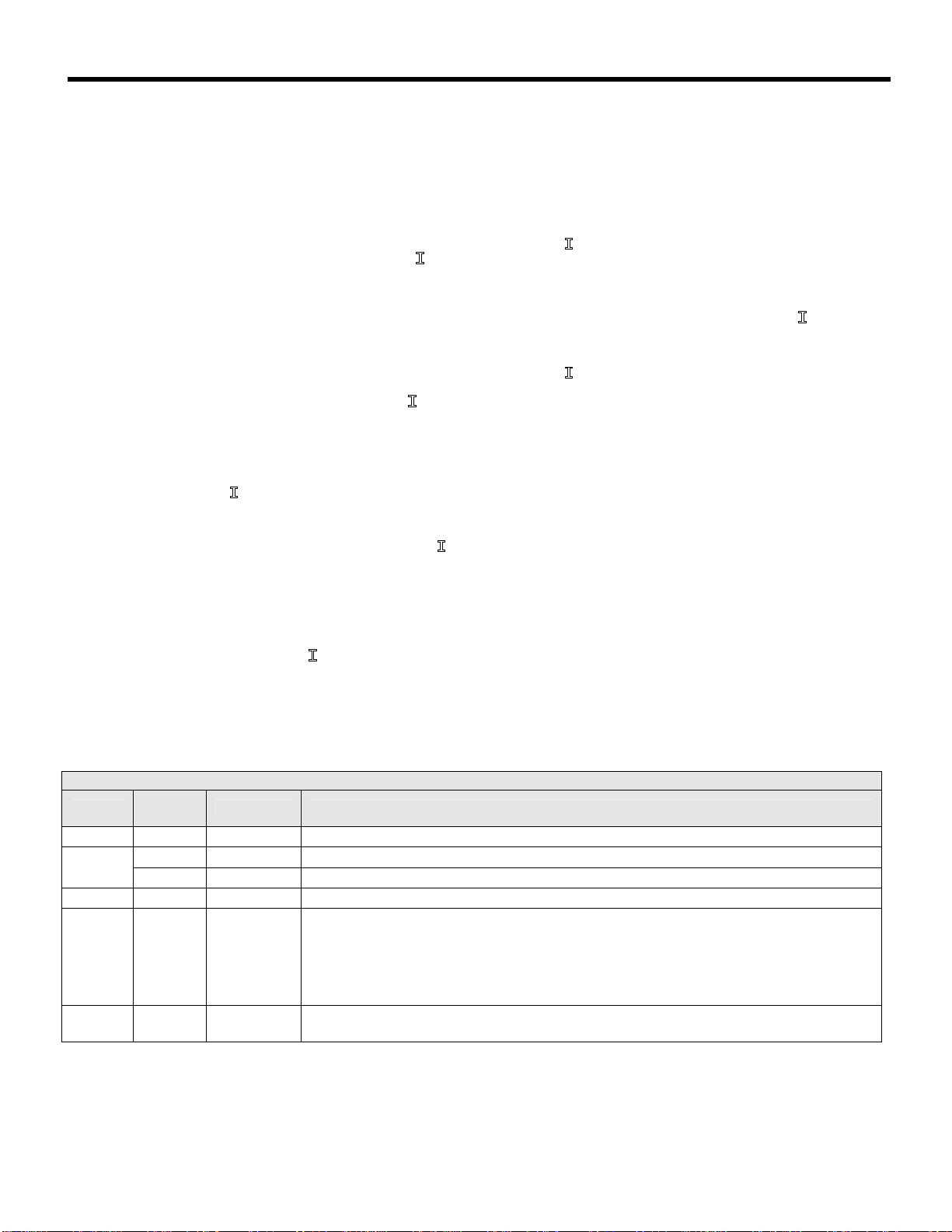
F-C F F-C Unit Selection (°F or °C)
RSt - -
Reset from lockout (manual reset only)
on Ready to restore from lockout
oFF Not Ready to restore from lockout
bac - - Return to Option Card View Mode Menu

Aquastat IQ Option Card – Instruction Sheet
Page 7 of 7
ORDERING INFORMATION
Part Number Description
102720-01 Aquastat Limit Control IQ Option Card, 130-220 Deg F, Manual Reset for use with
Option Control Panel, temperature sensor, well, sensor clip, instructions, Unit Pack
102717-01 Aquastat Limit Control, IQ Option Card, 130-220 Deg F, 15 Deg F Adjustable
Differential, Auto Reset, for use with Option Control Panel, temperature sensor, well, sensor clip,
instructions, Unit Pack
102292-01 Aquastat Limit Control IQ Option Card, 130-220 Deg F, Manual Reset for use with
Option Control Panel, Less well, Less Sensor, Unit Pack
102293-01 Aquastat Limit Control, IQ Option Card, 130-220 Deg F, 15 Deg F Adjustable
Differential, Auto Reset, for use with Option Control Panel, Less well, Less
Sensor, Unit Pack
TROUBLSHOOTING
Aquastat IQ Option Card Error Codes
The following errors are reportable via both EnviraCOM and the IQ Option Panel Display. Errors will be displayed in
view mode.
Display Status Boiler / Control Action(s)
Err 18 Internal Failure Replace Control
Err 119 Sensor Failure Temperature sensor or interface failure (open or short connection or
increased connection resistance, dual sensor mismatch) or control
hardware failure
Err 25 Lockout, manual reset
required
When a lockout occurs the boiler will shut down. The boiler will not
automatically restart once the temperature has decreased below the High
Limit. To Reset the control follow “Aquastat Reset Pushbutton procedure
described above.
U.S. Boiler Company, Inc.
P.O. Box 3079
Lancaster, PA 17604
This manual suits for next models
4
Table of contents