Burromax TT100R User manual

OWNERS MANUAL
TT100R MINI BIKE
READ AND UNDERSTAND THIS ENTIRE MANUAL BEFORE RIDING

CARTON CONTENTS
Located within top of the packing foam you will find the
front fender, rear fender, right and left footrest
assemblies, handlebar clamps, all hardware and tool kit.
The front wheel and charger are located at the bottom of
the packaging.
OPEN THE TOP OF THE SHIPPING BOX and remove the
contents from the top of the foam inserts. Inspect and
confirm that you have all parts and hardware. Remove the
foam separators that protect the components from
damage during shipping. Remove the front wheel and
brake rotor. Inspect the contents of the box for scratches
in the paint, dents or kinked brake lines that may have
occurred during shipping. Because these vehicles are 90
percent assembled and packed at the factory, there
should not be any problems, even if the box has a few
scars or dents.
Allow up to 30 Min for assembly.
Check for all parts and hardware before beginning
assembly. Follow these instructions carefully, Checking all
bolts, nuts and screws for tightness during the assembly
process.
Set the bike on a stable platform at least 18” o the
ground. Position the front fork so that it hangs o one end
of the platform to facilitate front wheel and brake
assembly installation.
Enjoy the process and take your time to ensure all
components are secure.
Checking all bolts, nuts and
screws for tightness during the assembly process.
2

ATTACHING THE HANDLEBARS AND
WIRING
Tools required: 6mm, 5mm, 3mm,2.5mm Allen wrench
Place the handlebars in the lower handlebar clamps
(adjust the lower clamp if needed by turning its mounting
bolt from underneath) on top of the front fork. Make sure
brake lines are not twisted or kinked and wires are free
from the clamps. Loosely install 2 top handlebar clamps
and (4) 8mm Allen bolts.
Center handlebar in clamps and position straight up or
slightly forward to fit rider height. Tighten the bolts using
a 6mm Allen wrench. When properly tightened the
handlebars should not move forward or back. Recheck
and retighten lower handlebar clamp fasteners.
ATTACH THE WIRES
The wires have color coded ends and will only fit to the
same color connector. Put the wire ends together and
rotate slowly until you feel the connectors align with each
other. Then gently push together till you feel the
connectors snap into place. Do this with all wire
connections.
BRAKE LEVERS AND THROTTLE
Rotate the brake levers into a good riding position and
tighten the clamp bolts using a 5mm Allen wrench. Rotate
the throttle to a good operating position and tighten using
a 3mm Allen wrench leaving space between the lever
mount and the throttle body. Rotate the headlight and
horn switch to a comfortable position and tighten using a
2.5mm Allen wrench. Turn the front fork from side to side
making sure that the wires and brake lines are free from
binding and clear of the fork stop located behind the
headlight.
INSTALLING THE FRONT FENDER
Using (4) 6mm Allen bolts with nuts, attach the front
fender to the fork legs and securely with a 5mm Allen
wrench. Remember the fender is plastic so do not over
tighten bolts.
3

INSTALLING THE FRONT WHEEL
Install the front axle into the left fork leg far enough to
install the first wheel spacer. Hold the front wheel up with
the brake rotor to the brake caliper side of the front fork
and insert the axle into the wheel. Twist the axle back and
forth to slide it through the bearings and spacer in the
wheel. Install the 2nd wheel spacer between the fork and
wheel on the opposite side. You may have to spread the
forks slightly to get the spacer in between the axle and
fork. Slide the axle all the way through the forks and
install the axle nut. Tighten securely. Make sure the front
wheel spins freely after you have tightened the axle nut.
INSTALLING THE FRONT BRAKE
CALIPER
Remove the caliper mounting screws from the brake
caliper or caliper mount bracket on the front fork. Install
the caliper over the brake rotor, align the mounting holes
and install the mounting bolts (Fig 1) hand tight. Before
tightening the mounting bolts, loosen the caliper
adjusting bolts (Fig 2) ½ turn so that the caliper is loose
on the mounting bracket. Once the caliper adjusting
screws are loose, you can now tighten the caliper
mounting bolts lightly.
Fig 1
Fig 2
4

ADJUSTING THE BRAKE CALIPER
After you have tightened the brake mounting bolts,
squeeze the brake lever a couple times to set the position
of the caliper. Squeeze the brake lever one more time and
hold pressure on the lever while tightening the caliper
adjusting bolts (Fig 2). This will align the caliper and
brake pads. The rotor should be running parallel and
central to the caliper body. When depressed the brake
lever should be approximately 1 inch or more o the hand
grip and have a firm feel. The front wheel should roll
freely without dragging on the brake when this operation
is complete
INSTALL THE REAR FENDER
Using (3) 6mm Allen bolts, attach the rear fender to the
top of the rear fork just behind the rear shock. Tighten
securely with a 5mm Allen wrench. Remember the fender
is plastic so do not over tighten bolts.
INSTALLING THE REAR SHOCK
The rear shock is mounted to the top shock mount under
the seat. Swing the shock down into place and install the
special 2 piece bolt supplied in the parts.
CHECKING THE TIRE PRESSURE
Both tires should be set to 40-45 P1SI. We strongly
recommend 45 PSI for persons over 175 lb when riding
this product. Proper tire pressure is VERY IMPORTANT.
Do not squeeze the tire and assume its OK—Check it!
INSTALLING THE FOOTREST
The footrests are made to fit on the right and left. MAKE
SURE YOU ATTACH THE FOOTRESTS SO THAT THEY
FOLD TOWARD THE BACK OF THE BIKE. Using (4) 10mm
hex bolts and lock nuts attach the footrests and brackets
to the bottom of the frame just below the battery box.
Using 14mm and 15mm wrenches tighten the bolts and
nuts securely.
KEY SWITCH OPERATION
All TT Series minibikes come with keyed switches so that
use can be restricted to owners and parental control is
available. We send 2 keys with each unit and we highly
recommend you save one of these keys in a safe place.
The TT1000R has a three (3) position switch. The first
position (1) is OFF, the second position (2) allows all lights
and USB ports to operate without power to the motor.
This is useful when using the lights, charging cell phones
and using other accessories without the possibility of the
5

vehicle taking o due to someone accidentally twisting
the throttle. In the third position (3), lighting, USB port
and motor are All ON and the bike is fully functional.
CHARGING THE BATTERY
Your TT1000R has a charging port located on the left
side of the battery box as shown in Fig (4). To access the
plug rotate the charger port cover away from the battery
box housing. This plug must be orientated properly for the
plug to connect and the charger plug can easily be turned
until the charger port pins align allowing the connection
to be made.
Fig 4
The charger box has a small window with one LED to
indicate the charge status. A green light indicates the
charger is on and a red light indicates the charger is
charging. When the battery is fully charged the indicator
will change from a red light to a green light signifying the
battery is fully charged. The charger will get warm during
use, this is normal and is no cause for concern. If your
charger does not get warm during use, it does not mean
that it is not working properly.
For the first 5 charge cycles we recommend that you
discharge the battery to 45 volts and then fully recharge,
uninterrupted until the battery is full. Typical recharge
time: up to 4 hours, depending on level of depletion. After
the first 5 discharge cycles, shorter charging times or
partial charging is okay. You will get over 75% charge in
3.5 hours. There is no need to fully cycle the battery every
time you ride with Lithium batteries. You can ride for an
hour and charge to full again if you like. When the
minibike is not in regular use, recharge the battery at
least once every 3 months until normal use is resumed.
Turn power switch “OFF” before charging and conducting
any maintenance procedures. Expect up to 600 charge
and discharge cycles. Charging and discharging the
battery in extreme temperatures above 110° F and below
32° F can cause damage to the battery.
The Burromax Li-ion battery and charger are to be used
together. Do not use chargers from other model
bikes—USE ONLY Burromax battery chargers.
WARNING: Rechargeable batteries are only to be charged
under adult supervision. Always disconnect your electric
mini bike from the charger when the battery is fully
charged and before cleaning with liquid.
6

MODES OF OPERATION
Standard Mode: Maximum performance of the bike
allows the controller to provide power instantly when
on/o throttle during riding.
Saver Mode: Reduction in take o power and longer
transition to full power but will reach maximum speed.
On/o throttle will moving is not instant. Great for when
in crowds, just cruising and saving battery power.
SAVER AND STANDARD MODE
OPERATION
The control for these modes are located on the handlebar
and operated by depressing and releasing the large red
button. This will change the mode from standard to saver
or vice-versa. The gauge shows a small Sat the 6 o’clock
position when you are in saver mode and will disappear
when you are in standard mode.
All Burromax electric bikes are set on saver mode and the
hi-low speed button should be in the low position when
they are shipped. You should change this setting only
when you feel the rider can control the vehicle at higher
speeds. You can change this setting while the bike is
in motion.
High and Low Speed
The H/L Function is available so you can limit the speed of
the bike when appropriate—it's also hidden so it cannot
be easily accessed.
There are 2 hidden switches on the battery box, one on
each side of the bike. One will control the side lights and
the other will control the H/L function.
When you depress the hidden button one time with the
small key tool supplied on your keyring you will notice the
multi-function gauge will display an Hfor high and a L
low on the left side of the gauge.
When on Hthe bike is capable of 30+mph. On Lbike is
capable of 15 mph.
SIDE LIGHTING
The side lighting is OFF when the bike is received.
We have incorporated LED lights on the sides of the bike
for both safety and utility. These lights can help you be
seen in daytime and nighttime running and are especially
useful as a camping light. The lights can be turned on or
o by depressing the hidden switch using a small tool as
shown (fig 5 B)
Fig 5
7

FEATURES AND CONTROLS
8

PRE-RIDE
CHECKLIST
LOOSE PARTS
Check and secure all fasteners before every ride. Make
sure handlebar clamp bolts are locked properly in place.
There should not be any unusual rattles or sounds from
loose parts or broken components. If you are not sure, ask
an experienced mechanic to check.
BRAKE
Check the brake for proper function. When you squeeze
the lever, the brake should provide positive braking
action. When you apply the brake with the speed control
on, the brake cut-o switch will stop the motor. When the
brake is not in use, the front and rear wheel should spin
freely without drag.
FRAME, FORK AND HANDLEBARS
Check for cracks or broken connections. Although broken
frames and chassis components are rare, it is possible for
an aggressive rider to jump, run into a curb or wall and
wreck, bend or break a frame, fork or suspension
components. Get in the habit of inspecting yours
regularly.
SAFETY GEAR
Always wear proper protective equipment such as an
approved safety helmet, elbow pads and knee pads.
Always wear athletic shoes (lace-up shoes with rubber
soles), never ride barefooted or in sandals, and keep
shoelaces tied and out of the way of the wheels, motor
and drive system.
RIDERS SAFETY
WARNING
This Mini Bike is designed for O Road
Use Only and has been designed and intended for
use in controlled environments free of potential trac
hazards and not on public streets. It is up to the end
user to know the local laws governing such vehicles
and where they are legal to be ridden. Burromax
makes no claim that these bikes are street legal.
Riding an electric mini bike can be a hazardous activity.
Certain conditions may cause the equipment to fail
without fault of the manufacturer. Like other electric
products, these vehicles can and are intended to move,
and it is therefore possible to lose control, fall o and/or
get into dangerous situations that no amount of care,
instruction or expertise can eliminate. If such things occur
you can be seriously injured or die, even when using
safety equipment and other precautions.
RIDE AT YOUR OWN RISK AND USE COMMON SENSE.
It is your responsibility to review this information and
make sure that all riders understand all warnings,
cautions, instructions and safety topics and assure that
young riders can safely and responsibly use this product.
Burromax recommends that you periodically review and
reinforce the information in this manual with younger
riders, and that you inspect and maintain your product to
insure rider safety.
The recommended minimum rider age is 16 years or older
is only an estimate, and can be aected by the rider’s size,
weight or skills. Any rider unable to fit comfortably on the
mini bike should not attempt to ride it. A parent’s decision
to allow a person younger than 16 years old to ride this
product should be based on the child’s maturity, skill and
ability to follow rules.
DO NOT exceed the maximum recommended rider weight
of 300 lbs. Rider weight does not necessarily mean a
person’s size is appropriate to fit or maintain control of
the vehicles.
Keep this product away from small children and
remember that this product is intended for use only by
persons who are completely comfortable and confident
when operating this mini bike.
Do not touch the brakes or electric motor on your electric
mini bike when in use as they can become very hot.
Always check and obey any local laws or regulations
which may aect the locations where the vehicles may be
9

used.
Ride defensively. Watch out for potential objects that
could catch your wheel or force you to swerve suddenly or
lose control.
Be careful to avoid pedestrians, skaters, skateboards,
scooters, bikes, children or animals who may enter your
path, and respect the rights and property of others.
Do not activate the throttle on the hand grip unless you
are on the electric mini bike and in a safe, outdoor
environment suitable for riding. These bikes were
manufactured for performance and durability but are not
impervious to damage. Jumping or other aggressive riding
can over-stress and damage any product, including this
electric mini bike, and the rider assumes all risks
associated with high-stress activity.
Be careful and know your limitations. Risk of injury
increases as the degree of riding diculty increases. The
rider assumes all risks associated with aggressive riding
activities. Maintain a hold on the handlebars at all times.
Never carry passengers or allow more than one person at
a time to ride the electric mini bike without proper skills
and accessories. Never use near steps or swimming pools.
Keep your fingers and other body parts away from the
drive chain, wheels, brake rotors, steering system, and all
other moving components. Never use headphones or a cell
phone while riding this bike. Never hitch a ride with
another vehicle.
Do not ride the vehicles in wet or icy weather and never
immerse the electric mini bike in water, as the electrical
components and drive components could be damaged by
water or create other hazards or possibly unsafe
conditions. These vehicles are intended for use on smooth
ground without loose debris such as rocks or gravel. Wet,
slick, bumpy, uneven or rough surfaces may impair
traction and contribute to possible accidents. Do not ride
the electric mini bike in mud, ice, puddles or water. Avoid
excessive speeds that can be associated with downhill
rides.
PROPER CLOTHING
Always wear an approved safety helmet (with chin strap
securely buckled). A helmet may be legally required by
local law or regulation in your area. Long pants and gloves
are recommended. Always wear boots or athletic shoes
(never ride barefooted or in sandals, and keep shoelaces
tied and out of the way of the wheels, motor and drive
system.
BATTERY AND CHARGER WARNINGS
1. The charger supplied with the electric mini bike
should be regularly examined for damage to the
cord, plug, enclosure and other parts, and in the
event of such damage, the bike must not be
charged until the charger has been repaired or
replaced.
2. Use ONLY Burromax Li-ion Battery Charger
Specific to the TT1000R.
3. Do not operate a charger near flammable
materials.
4. Unplug charger and disconnect from bike when
not in use.
5. Chargers are not waterproof and should never
be used in wet conditions. Water and moisture
will damage the charger so always use the
charger in a clean, dry area
6. Do not store or charge the battery in extreme
temperatures. Above 110° F or below 32° F
7. Keep away from fire.
8. Do not disassemble the battery.
9. Do not use lead acid or automotive battery
chargers as it will damage the battery and void
your warranty.
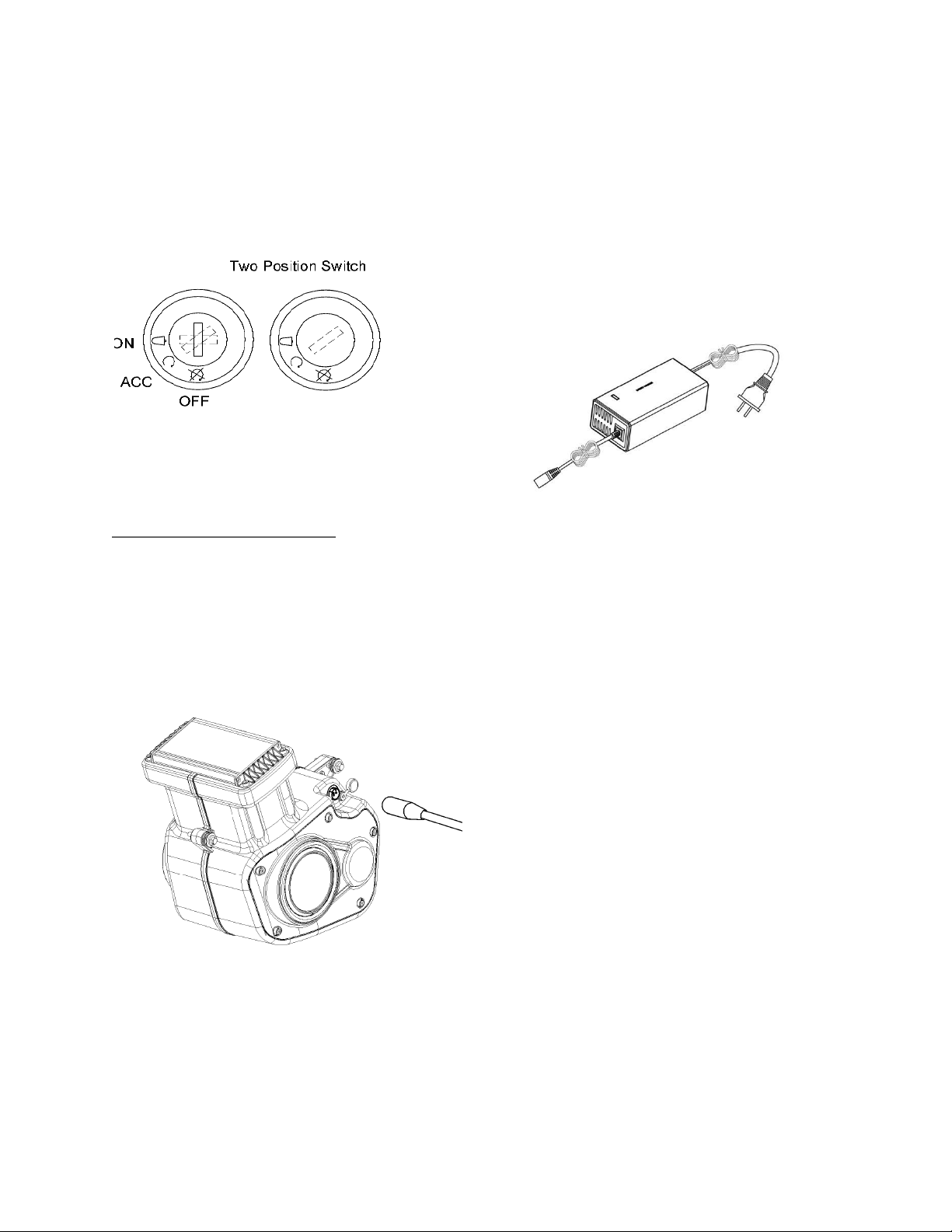
10. Turn the power switch OFF before charging the
battery or conducting any maintenance
procedures.
FAILURE TO USE COMMON SENSE AND HEED
THE ABOVE WARNINGS INCREASES RISK OF
SERIOUS INJURY. USE WITH APPROPRIATE
CAUTION AND SERIOUS ATTENTION TO SAFE
OPERATION.
Recycle batteries at locations that accept
Lithium Ion Batteries—DO NOT THROW IN THE
TRASH
10

POWER WASHING WARNINGS
Use care when washing to avoid pointing the water
streams directly at the electrical components. Avoid
pointing the water at the throttle and speedometer,
brake handles, and the ends of the motor. Do not use
high pressure to wash the plastic body or the
hydrographics may come o! Do not put water directly
into the battery housing vents! High pressure washing
tires, wheels, brakes and under the bike or frame
components poses no danger to the bike when washing.
Be careful and be thoughtful of all wiring and electrical
components when washing.
OPERATION AND
PERFORMANCE
NOTES
This bike was intended for enjoyment for the entire family
as a pit bike, camping bike, hunting mobility or to cruise
around the property on. It was designed specifically as
an o-road motorcycle. This bike was not intended for
use as a competition or motorcross bike and should
not be used to jump, ride wheelies or stunt on.
We recommend riders up to 300 lbs use this bike on
relatively flat hard packed surfaces and lighter weight
riders have more freedom on terrain and riding
aggressiveness.
WARNING: Do Not Operate this vehicle in WATER
or SAND.
Water and sand can damage the motor which has AIR
VENTING and COOLING HOLES in each end. Keep water
and sand away from the motor!
These vehicles are intended for use on hard packed
ground without loose debris such as rocks or gravel and
sand. Wet, slick, bumpy, uneven or rough surfaces may
impair traction and contribute to possible accidents. Do
not ride the electric mini bike in mud, ice, puddles or
water. Avoid excessive speeds that can be associated with
downhill rides! This bike can achieve high speeds on
downhill rides which can cause the rider to lose control
and cause injury or even death.
RUNNING TIME
Run time may vary depending on many factors such as
riding conditions, rider weight, climate and/or proper
maintenance.
Distance and performance testing was done with 200 lb
riders and these bikes were tested to have a 35 Mile
range on the low setting in saver mode ( 15 mph) and
nearly 18 miles on the high setting in saver mode
(30mph).
Testing was done on flat ground with wide open throttle
with calm weather. These bikes were tested from full
charge to cuto voltage and we don’t recommend this
type of usage as the normal. You should familiarize
yourself with the voltmeter located on the handlebar
gauge and the voltage displayed while the bike is under
power and moving. You will notice the voltage changes
with the power load required, this is normal. At full charge
you should see approx. 54V and cut o is approx. 39.0V.
The most common cause of low performance is LOW
TIRE PRESSURE and BRAKE DRAG. Please ensure tire
pressure is maintained for optimum ride time and
performance and that the wheels turn freely.
RIDING UNTIL THE BATTERY IS
COMPLETELY DEAD
This bike will completely shut o at approximately 39.0V,
which is displayed on the handlebar gauge. This always
happens under load or while riding the bike. Even though
you gauge shows a higher voltage while sitting, as
soon as the throttle is turned when riding the voltage
drops. Look for the voltage drop while riding your bike
and understand where you should recharge without
worrying about having to push your bike home. The
voltage is always displayed on the gauge while riding.
We do not recommend running the bike to cuto, as it is a
real pain to push your bike home. If this happens to you,
you can wait approx. 3-5 min and the battery voltage will
rise enough to allow you one short ride if you are gentle
11

with the throttle, but don’t expect to go far. If you do run
the bike until cuto, we recommend that you recharge the
battery immediately after you have run the battery below
this voltage.
DO NOT LET A DEAD BATTERY SIT FOR A LONG PERIOD
OF TIME. If you allow these batteries to sit for long
periods of time when fully discharged you may risk being
unable to recharge the battery.
REPAIR AND
MAINTENANCE
Warning: Turn power switch “OFF” before conducting any
maintenance procedures.
SERVICING THE BRAKE
The TT1000R is equipped with cable brake systems front
and rear. For assistance on adjusting your brake we
recommend going to Youtube: Burromax Channel and
location the service video provided.
TESTING THE BRAKES
To test the brake, squeeze the lever to increase the
pressure on the brake. When depressed the brake lever
should be approximately 1 inch or more o the hand grip
and have a firm feel. The wheel should roll freely by hand
when the brake is not applied and the brake should lock
up when applied with force.
WARNING:The brakes can cause the electric motorbike to
skid the tire throwing an unsuspecting rider. Practice in
an open area free from obstacles until you are familiar
with the brake function. Avoid skidding to a stop as this
can cause you to lose control.
Note: Brakes that are poorly adjusted can be draggy and
will cause excessive wear and poor performance.
CHAIN ADJUSTMENT, REAR TIRE AND
CHAIN REPLACEMENT
Tools required: 5mm Allen wrench, 2- 10mm wrenches,
14mm, 17mm wrench and chain lube.
Set the bike on a stable platform so that the rear wheel is
o of the ground. To adjust the chain only perform steps
3, 6, and 7
To replace and adjust the chain perform steps 1, 3, 5, 6,
and 7
To replace or repair the rear tire perform steps 1, 2, 4, 6,
7, 8, 9, 10,
Use a 5mm Allen wrench and remove the chain cover
screws and slide chain guard to the back of the mini bike.
If replacing the tire remove the two brake caliper
mounting bolts (5mm Hex Key) and remove the caliper.
Adjusting or replacing chain only use 14mm and 17mm
wrenches, loosen the axle, approximately 2 full turns.
Remove the rear wheel, remove axle nut and axle and
remove the chain from the sprocket--pull the wheel out.
Note the sequence of the hardware for assembly.
12

Replacing the chain requires removal of a master link.
Removing the outer retainer allows this link to be
disassembled and removed. Be careful not to damage the
Retaining clip. Note. Install clip as shown (fig.X)
WARNING: Make sure the power switch is in o position
before performing any maintenance.
WARNING: To avoid a pinch or injury keep fingers away
from moving sprockets and chain.
TT1000R AXLE ASSEMBLY
B-1 Rear Axle
B-2 Rear Axle Adjuster Plate (2)
B-3 Rear Axle Spacer-Sprocket and Disc Sides -Outer (2)
22mm
B-4 Caliper Mounting Plate
B-5 Rear Axle Spacer-Disc Side –Inner ONLY-22mm
B-6 Rear Tire
B-7 Rear Axle Nut
1. Install the new chain by lacing the chain around
the motor sprocket. Maneuver the chain onto
the sprockets on the rear wheel and motor. Pull
the chain tight. Place both ends of the chain at
10 o’clock on the rear wheel sprocket. This will
make it easier to install the master link. Slide
the master link into the chain with the pins out,
place the outer side link onto the protruding
master link pin. Push the link together so that
you can see the retaining clip grooves in the
pins. Lay the retaining clip over the pins with
the open end toward the back of the bike and
slide the clip in place using a pair of pliers.
Make sure the clip is locked in place.
2. Roll the wheel while feeling the slack in the
chain and find the tightest spot in the chain.
Using two 10mm wrenches. Hold the adjusting
bolt and loosen the jam nut on the chain
adjuster bolts. Turn the chain adjuster bolts one
flat at a time counterclockwise to tighten the
chain adjusters. Work both sides evenly to
remove slack from the chain as required. Keep
rolling the wheel while checking the free play in
the chain. (fig A) When you have ½” of free play
in the chain at the tight spot, tighten the axle
nut. Recheck chain free play by rolling the wheel
around again to find the tight spot and confirm
that you still have the ½” free play. Hold the
axle adjusting bolt with one 10mm wrench and
tighten the jam nut with the other 10mm
wrench. Recheck for free play and that the rear
wheel rolls freely.
3. Now is a good time to lube the chain with chain
lube. Slowly roll the wheel while spraying chain
lube on the inside of the chain. Roll the wheel a
few more times to work the chain lube into the
chain. Do not spin the rear wheel for 10-15
minutes after chain lube has been applied.
13

1. Reinstall the rear brake caliper. After the caliper
has been reinstalled, spin the rear wheel by
hand and squeeze the brake lever to make sure
the wheel spins freely and the brake works
properly.
2. Slide the chain guard back in place and reattach
using two 6mm Allen screws. Tighten using a
5mm Allen wrench.
3. Test ride.
CHAIN AND SPROCKET NOTES
The chain will typically have a “loose spot” and “tight
spot” corresponding with a sprocket rotational position.
This is normal and common to all chain-driven products
due to run-out tolerances of the sprockets. The chain
should be adjusted to the ideal tension with the chain in
the tightest spot.
Proper chain alignment must be maintained. The wheel
must not be skewed. If the chain is noisy or rough
running, check the lubrication, tension and alignment of
the sprockets, in that order.
WARNING: To avoid a pinch or injury keep fingers away
from moving sprockets and chain.
BATTERY REPLACEMENT
WARNING: Make sure the power switch is in o position
before performing any maintenance.
Li-ion battery (1-48v-17.6ah) contains a non-replaceable
internal breaker. Only use the Burromax Li-ion battery
and Li-ion battery charger together. Do Not attempt
to replace this battery with anything other than the
OEM battery.
1. With the battery cover removed, disconnect the
hold down strap.
2. Slide battery set out of mounting tray.
3. Disconnect battery connection. Re-install new
battery and reconnect.
4. When reconnecting the new battery you may
get a small spark.
5. Tuck in wires and reassemble.
6. See www.burromax.com for order.
14

Specifications
WEIGHT
Shipping Weight 93.5
Bike Weight 81.5 lb.
PERFORMANCE
High Speed: 30-32 Mph on Standard/Saver Mode
Low Speed: 20-22 Mph on Standard or Saver Mode
RANGE
(Tested using 200 lb. Rider on Flat Pavement)
High--Up to 20 Miles
Low--Up to 36Miles
CHARGE TIME
100% Discharge approx. 4.5 Hrs to full recharge
80% Charge in 2.5 Hrs.
WEIGHT CAPACITY
Up to 300 lbs. on Flat Pavement/Dirt
For O Road Riding we recommend 180 lb max
ELECTRICAL
Battery: 48 Volt 17.6AH Lithium Ion
Charger: 54.6V 4 Amp
Controller: 4 Modes, Hi/Lo Speed Handlebar
controlled, Standard/Saver Mode is hidden switch,
Locked Wheel Cut
Wiring: Waterproof *** Type
Motor: Brushless DC 1000W Rated
Lighting: LED Headlight, LED Taillight
LED Safety Side Lights
Display: MPH, Odometer, Voltage, Charge Bar
Graph, Hi/Low
USB Ports: Dual 4.5 Amp Fast Charging
Horn: Single Note 120 db
CHASSIS
Fork: 25mm Conventional Hydraulic
Rear Shock: 160mm Coil Over Hydraulic-Adjustable
Wheel: 3.5x8” 6 Spoke Alloy
Tire: 90-65-8” Burromax Track Tire
Brakes: 160mm Mechanical Disc F/R
15

CALIFORNIA PROP 65 WARNING
Burromax Limited
Warranty
If you have defects of quality or workmanship Burromax
will send you replacement parts free of charge for a
period of 90 days from date of purchase. This Limited
Warranty does not cover normal wear and tear, tires,
tubes, chain or any damage, failure or loss caused by
improper assembly, maintenance, or storage or use of
these products. Batteries are warranted 2 years from
date of purchase. The manufacturer is not liable for
incidental or consequential loss or damage due directly or
indirectly to the use of this product.
Burromax does not oer an extended warranty. If you
have purchased an extended warranty, it must be honored
by the store at which it was purchased. For your records
save your original sales receipt with this manual, Fill Out
the product registration page and mail it to:
Burromax
1 Chesterfield Mall
Chesterfield MO 63017
All Warranty requests will be evaluated by Burromax and
final determination will be made at our sole discretion.
This Limited Warranty will be void if the product is ever:
●used in a manner other than for recreation specified in this manual
●modified in any way;
Replacement parts are available at
www.burromax.com
1-800-742-1189
16
Table of contents