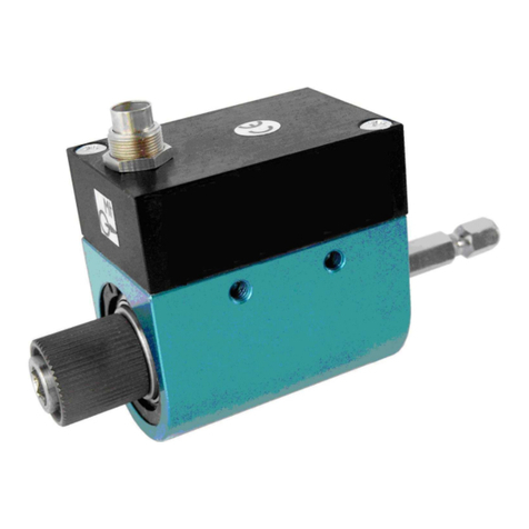
Burster 8402 Series User manual

Type 8402
Technical Product Information
Start-up, Operation, Installation Instructions
-1-
burster präzisionsmeßtechnik gmbh & co kg .Talstr. 1-5 D-76593 Gernsbach (P.O.Box 1432 D-76587 Gernsbach) Tel. +49-7224-6450 .Fax 645-88
Miniature Load Cell Type 8402
1. Introduction
The load cells of the series Type 8402 are primarily designed for force measurements in the unit N in conjunction with
manufacturing facilities.
When determining masses it is important to take the local acceleration of free fall (g ≈9.81 m/s2) into consideration.
2. Preparation for operation
2.1 Unpacking
Carefully check the sensor for damage. Should transport damage be suspected, please notify the supplier within
72 hours. The packaging must be kept for inspection by the manufacturer's representative and/or the supplier.
Transportation of the Type 8402 may only be performed in the original or equivalent packaging.
2.2 Start-up
The load cell is connected exclusively to measurement amplifiers equipped with a safety transformer as specified
according to VDE 0551. Even the transmitter and devices connected downstream, which are electrically connected to
the sensor's signal lines, must be equipped with a safety transformer according to VDE 0551.
2.3 Grounding and isolating
All lines are isolated from the housing, however the maximum permissible voltage is 30 V. The cable shielding is not
connected on the sensor-side.
2.4 Storage
The sensor must be dry stored at 0 ... 60 °C. Dampness is not permitted. Special measures need not to be taken for
commissioning after storage.
3. Operating principle
A load cell consists of a spring element which is deformed by the applied force being measured and a device which
measures this deformation.
3.1 Spring element
The spring element constitutes the most important mechanical component of the load cell. It is designed to absorb the
load being measured and to transfer it to an area of homogenous extension. Here the elastic properties of the spring
materials are used to indirectly determine the load. In addition to these elastic properties the materials used in load cells
must also meet other conditions with the result that only a few selected materials come into question for high-quality
sensors. burster goes one step further and primarily uses aviational materials instead of DIN-approved materials, as
these have additional quality requirements.
In the Type 8402 the spring is designed as a hollow compressible body (Fig. 1). Here the force being applied influences
the height of the spring - compressing it. This simultaneously increases its diameter. These deformations are so slight
that they are invisible. Characteristic here is the small body in relation to the nominal load which in conjunction with the
high spring rate ensures a high resonance frequency and thus permits rapid measurement.
Elongation or strain measurement:
The elongation of the spring's surface is measured using strain-gauges, see Fig. 2. The gauges are attached to the
spring of the load cell making them subject to the same deformation as the spring. As such the elongation and therewith
the force can be measured electrically. In the Type 8402 the strain gauges are attached to the inner side of the spring
element.

Technical Product Information
Start-up, Operation, Installation Instructions Type 8402
-2-
burster präzisionsmeßtechnik gmbh & co kg .Talstr. 1-5 D-76593 Gernsbach (P.O.Box 1432 D-76587 Gernsbach) Tel. +49-7224-6450 .Fax 645-88
4. Installation instructions
4.1 Mechanics
Force application
The way force is applied is of primary importance to the quality of measurement. This must be carried out so that the
force's line of application coincides exactly with the geometric axis of the load cell (centric load). It is also of great
importance that no side forces and torques are applied to the load cell.
Side forces mainly arise due to excentric load, slanted or oblique force application and as a result of friction arising from
moveable parts. Friction occurs at parts which are not hardened enough or whose surface quality is insufficient.
The parts where force is being applied must be even (not convex), ground and as lapped as possible. The working
material must be fully hardened (not just surface hardened) and demonstrate at least 60 HRC.
There are no bore holes in the part where force is being applied, also no central bore hole is permitted for the lathes.
Regarding the function of the strain gauges (foils):
The resistance of a wire rises with increasing length and decreasing cross-section. If you pull on a wire, it becomes
thinner and longer. As a result its electrical resistance increases. The function of strain gauges is based on this principle.
In practice strain gauges do not consist of a round wire, but a metal foil, which is laminated onto the carrier material.
From this metal foil the meander-shaped resistance structure is etched out. Special techniques are used to attach this
foils to the surface of the spring element.
3.2 Connection
To reduce the effect of undesired variables the four strain gauges in the load cell Type 8402 are connected into a bridge
configuration (Wheatstone bridge), see Fig. 3.
The illustration shows the connection in simplified form. In addition to the strain gauges there are also compensation
resistors built-in to reduce temperature effects. Furthermore, depending on the design of the sensor, additional resistors
can be integrated for the output standardization of the sensor in the cable or plug.
The output voltage Uout of the sensor is computed as follows:
Uout = c .Ub
Where Ub is the operating voltage and c is the characteristic value of the sensor. The characteristic value c of the sensor
can be taken from the calibration certificate and is fixed at c =1.5 mV/V. In conjunction with operating voltages
Ub= 2.5 ... 5 V you typically obtain output voltages of Uout = 3.75 ... 7.5 mV.
F
+U weiß
Ua
-U braun
gelb
grün
ν
ε
ε
ε
ε
ν
Fig. 1: Spring element Fig. 2: Strain gauge foil Fig. 3: Strain gauge full-bridge

Type 8402
Technical Product Information
Start-up, Operation, Installation Instructions
-3-
burster präzisionsmeßtechnik gmbh & co kg .Talstr. 1-5 D-76593 Gernsbach (P.O.Box 1432 D-76587 Gernsbach) Tel. +49-7224-6450 .Fax 645-88
Mounting surface
The structure of the mounting surface is just as important for the quality of measurement attainable. For clarification:
Depending on the measuring range the measurement path of the spring of force sensor Type 8402 lies in the range from
approx. 3 µm up to 20 µm for full deflection. This also means that a modulation of 1% of the nominal force corresponds
to a measuring path of 0.03 µm up to 0.2 µm.
It is very important that the sensor lies flush with its contact surface on the underlying object to avoid any undesired
deformations of the housing. To rule out any distorting deformations of the underlying object, the object must be
sufficiently stable
and full hardened (not just surface hardened).
The sensor must be mounted with its entire surface on a
fully hardened
(60 HRC), ground, as lapped as possible,
non-laquered underlying object.
Surface quality: N 3 (Rz 1), flatness: 2 µm
There are no bore holes or machines pockets permissible in the surface of the underlying object.
Overload
Compressivebodiesarerelativelyinsensitivewithrespecttooverload.Anyoverloadofthesensorelementisrecognized
by an increased output signal without load. The sensor should be inspected starting at approx. 5 % signal increase of
the zero point.
Due to the small deflection it is virtually impossible to provide overload protection using a path stop directly
on the sensor. In many cases the sensor can be placed on a spring with a guided underlying object. This increases
the measuring path by the amount of the spring path and makes it easier to implement path limiters.
When loading is performed with hydraulic or pneumatic cylinders these can be equipped with pressure limiters.
Do not apply abrupt loads. The high spring rate of the sensor leads to short "braking paths" of masses in motion,
resulting in the generation of very high force levels.
Cables
The cables need to be laid out so that as little vibration as possible arises. Parameter defining components have been
integrated into the cable or plug. For that reason the cable cannot be shortened arbitrarily without reinstalling these
components.
The cable is equipped with a wrap around Teflon sheath. For that reason attention must be paid to large bending radii,
the cable sheath might also develop leakage if exposed to heavy vibration over time. If this occurs the load cell can be
damaged from penetrating fluid coming from the capillary effect (e.g. deposits of oil mist). Special measures must be
taken in the presence of vapours or fluids. Furthermore the cable may not be exposed to any tensile loads.
4.2 Attachment
In general
THE LOAD CELL MAY NOT UNDER ANY CIRCUMSTANCES BE SUBJECTED TO LATERAL TENSION OR BE
PRESSED INTO BORE HOLES.
Screws
The load cell is operated in the compression direction, for that reason fastening screws play a subordinate role. They
are merely used to attach the sensor.
The optimum method of attachment has proven to be the careful screwing of the flange of the sensor onto the underlying
object using a disk with 3 bore holes for max. M4. To do this it is expedient to minimize the sensor tension by observing
the connected evaluation electronics.
The disk must have an air gap of at least 0.5 mm to the measuring element (øD1).
Glueing
If there is not enough space to fasten with screws then the load cell can also be glued on. The load cell is attached to
the edge of the flange from
above
whereby the measuring element must remain free.
4.3 Electrical features
The output signal of the Type 8402 typically amounts to 3.75 ... 7.55 mV under full deflection. If you wish to measure
precisely to 1 % you must obtain a resolution greater than approx. 10 µV. To accomplish this it is necessary to prevent
any corresponding disturbances which these low signals produce from affecting the sensor, the sensor's lines and the
measuring instrument.

Technical Product Information
Start-up, Operation, Installation Instructions Type 8402
-4-
burster präzisionsmeßtechnik gmbh & co kg .Talstr. 1-5 D-76593 Gernsbach (P.O.Box 1432 D-76587 Gernsbach) Tel. +49-7224-6450 .Fax 645-88
For that reason, if it is at all possible avoid placing the load cell and the measuring instrument in the vicinity of powerful
switching stations or gears. (Examples: transformers, motors, contactors, frequency converters). The electromagnetic
fields could unabatedly affect the measuring instrument and load cell and thus lead to falsified results.
The measuring leads may not be laid in parallel to power carrying lines because inductive as well as capacitive
disturbances could get coupled into the measuring lines.
In some cases it has proven useful to pull an added screen over the measuring cable to give added protection or to lay
the cable in a metal tube or pipe.
5. Calibration of the measuring system
An existing measuring configuration comprising load cell and measurement amplifier can be calibrated using various
methods. Using methods 5.2 or 5.3 only the measurement amplifier is calibrated, that means only errors in the sensor
are tracked. If the corresponding equipment as stated under 5.1 is not available the load cell or the measuring
configuration can be calibrated in the factory.
5.1 With physical variables
Function
The load cell is fed with known physical variables.
Example: A scale or balancing device consisting of a load cell and a indicating instrument is relieved of load and the
zero point adjusted. Then a known reference weight is placed on the device and the final value is set.
Factory calibrating certification for the load cell or the entire measuring configuration can be performed on request -
also for recalibrations - in the factory on weight measuring systems.
For direct contact Mr. H. Bok +49-7224-64545
or Mr. H. J. Legat +49-7224-64557
5.2 With strain gauge simulator
Function
By the strain gauge simulator we mean a substitute bridge circuit comprising precision resistors, which is able to assume
various output states. The strain gauge simulator is connected to the measurement amplifier instead of the sensor
(e.g. with burster simulator Type 9405).
5.3 With precision voltage source
Function
The sensor is simulated using a precision voltage source (e.g. burster DIGISTANT®Types 4405, 4422), which is
connected to the measuring amplifier.
Note: Please bear in mind that in strain gauge full-bridge sensors the excitation voltage enters the measurement
result. It is possible that the actual feed voltage slightly deviates from the nominal feed voltage. If you would like to verify
the functionality of the measurement amplifier using voltage sources, you must measure the sensor excitation voltage
with a precision digital voltmeter and then calculate the calibration voltage.
5.4 Shunt calibration
Function
During shunt calibration a precision resistor (calibration shunt) is connected between (-) signal input and (-) excitation.
The precision resistor tunes the bridge so that for a certain degree of elongation it corresponds to a certain load of the
sensor.
This defined bridge tuning brings about a defined step change of the output signal with which the entire measurement
configuration is calibrated. The amplitude of the output signal's step change and the value of the corresponding
calibration shunt are specified in the calibration certificate of the sensor.
This method only tests the sensor's electrical function, its properties in a measurement circuit have not yet been verified.
Important note:
The authors have carefully prepared, compiled and reproduced all of the technical specifications and programs contained in this document using
stringent quality control measures. Nevertheless errors cannot be ruled out. For that reason burster präzisionsmeßtechnik feels obliged to point out
that neither a guaranty nor any kind of liability can be assumed for consequences resulting from faulty specifications, accidental damage or claims
thereof. Furthermore, there can be no guaranty for the material, quality or specific applicability. This document does not claim to be error-free and
is subject to technical alterations.
The authors are always grateful to receive any notification of errors contained herein. Version,Jan. 2002
Other manuals for 8402 Series
1
Table of contents
Other Burster Accessories manuals

Burster
Burster 86-2500 User manual

Burster
Burster 86-2800 User manual

Burster
Burster 8630 User manual

Burster
Burster 8631 User manual

Burster
Burster 9235 User manual

Burster
Burster 86-2208 User manual

Burster
Burster 86-2113 User manual

Burster
Burster 86403 User manual

Burster
Burster Burster User manual

Burster
Burster 86-2112 User manual