BUSCH DOLPHIN LN 3001 A User manual

Installation and
Operating Instructions
DOLPHIN
Liquid Ring Compressors
LN 3001 A
LN 3002 A
VACUUM APP
Get technical data,
instruction manuals,
service kits
2020.04.27
Busch GVT Ltd.
Unit A, Westmere Drive
Crewe, Cheshire CW1 6ZD
United Kingdom
0870223347/-0001_en / Original instructions / Modifications reserved

Table of Contents
2 / 24 0870223347_LN3001-3002A_-0001_IM_en
Table of Contents
1 Safety........................................................................................................................... 3
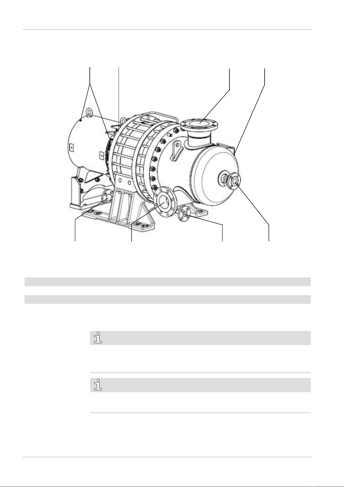
2 Product Description ..................................................................................................... 4
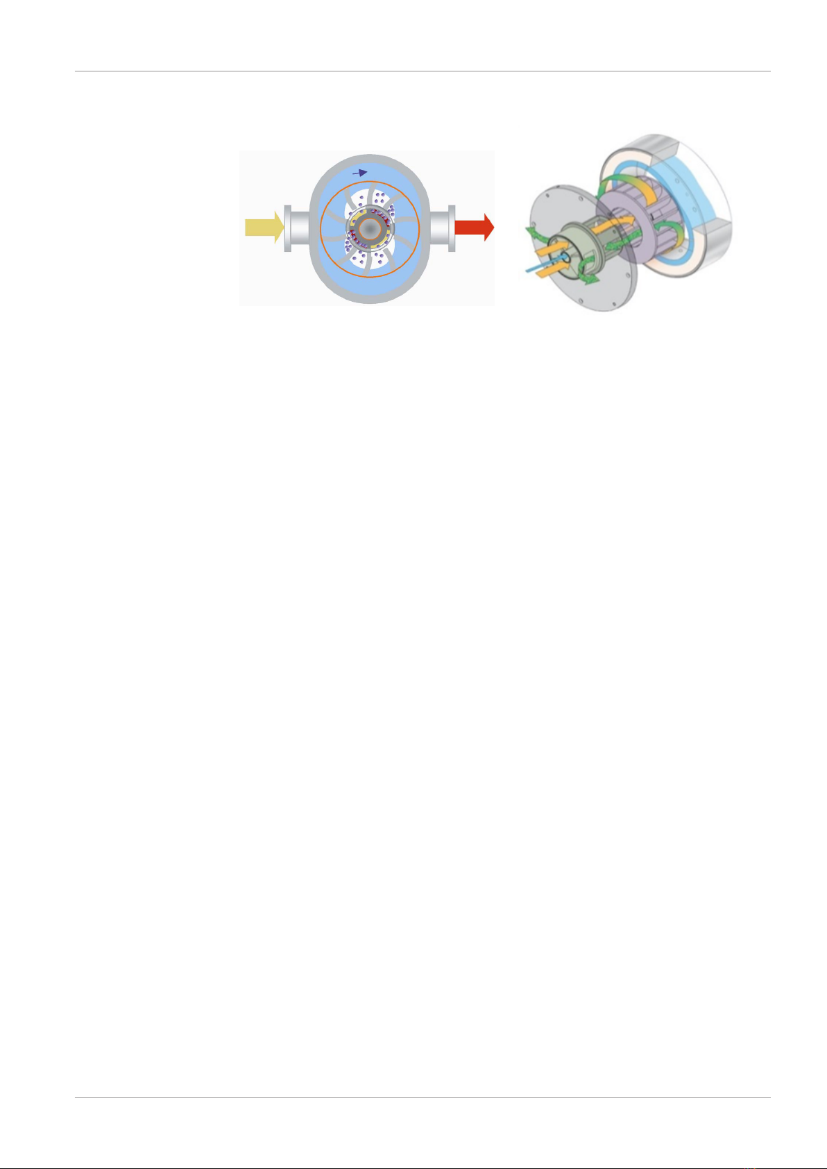
2.1 Operating Principle...............................................................................................5
2.2 Application ........................................................................................................... 5
2.3 Start Controls .......................................................................................................5
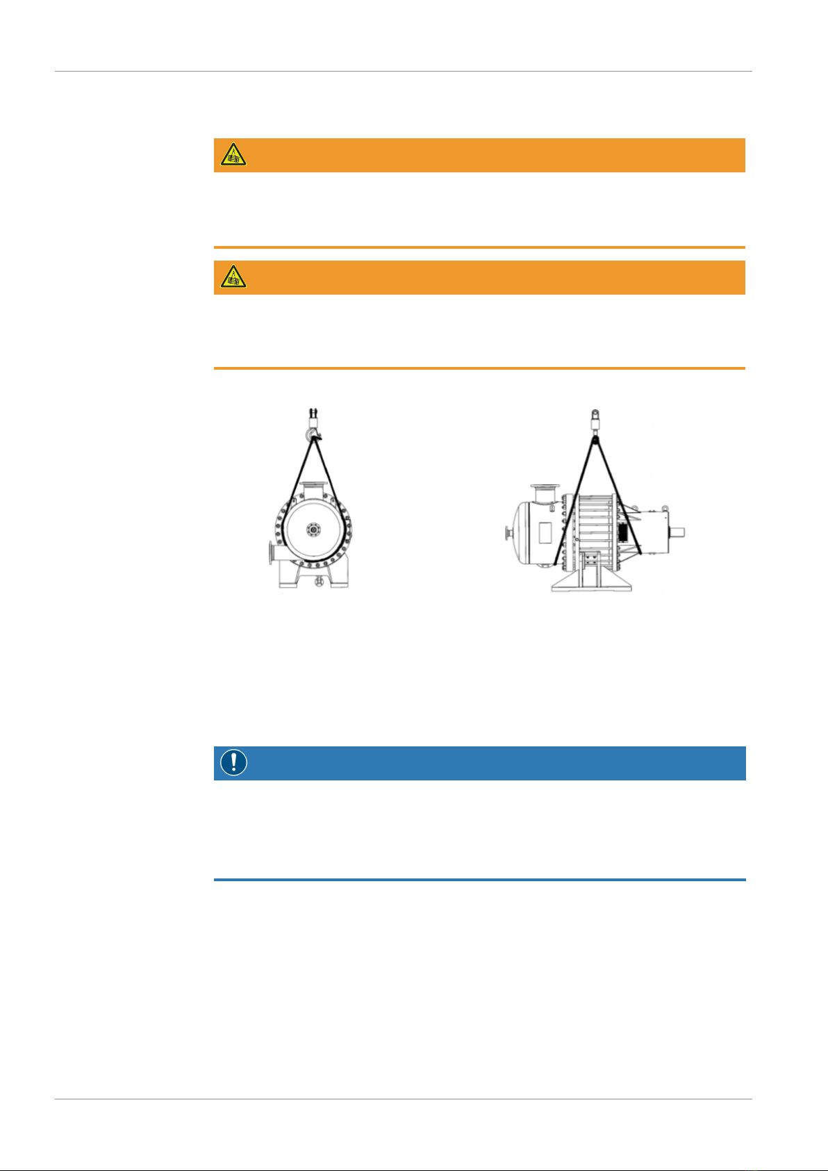
3 Transport ..................................................................................................................... 6
4 Storage......................................................................................................................... 6
4.1 Short Term (Up to 3 Months) ...............................................................................6
4.2 Medium Term (3 Months to 6 Months)................................................................7
4.3 Long Term (Over 6 Months).................................................................................7
5 Installation................................................................................................................... 7
5.1 Installation Conditions ..........................................................................................7
5.2 Connecting Lines / Pipes ......................................................................................8
5.2.1 Suction Connection....................................................................................8
5.2.2 Discharge Connection................................................................................8
5.2.3 Operating Liquid Connection.....................................................................9
5.3 Operating Liquid Settings .....................................................................................10
5.4 Fitting the Coupling..............................................................................................10
6 Commissioning............................................................................................................ 11
6.1 Start-Up ...............................................................................................................12
7 Maintenance................................................................................................................ 15
7.1 Maintenance Schedule..........................................................................................15
8 Overhaul...................................................................................................................... 18
9 Decommissioning ........................................................................................................ 18
9.1 Dismantling and Disposal......................................................................................19
10 Spare Parts................................................................................................................... 19
11 Troubleshooting........................................................................................................... 20
12 Technical Data ............................................................................................................. 22
2.2.1 LN Series ...................................................................................................5
13 EU Declaration of Conformity ...................................................................................... 23
7.2 Lubrication ...........................................................................................................16
6.2 Shut-Down ..........................................................................................................14
6.2.1 Regular Shut-Down...................................................................................14
6.2.2 Emergency Shut-Down..............................................................................14
6.1.1 First-Time Start-Up....................................................................................12
6.1.2 Regular Start-Up........................................................................................13
7.2.1 Grease .......................................................................................................16
7.2.2 Oil .............................................................................................................17
5.2.4 Mechanical Seal Connection ......................................................................9

Safety | 1
0870223347_LN3001-3002A_-0001_IM_en 3 / 24
1 Safety
Prior to handling the machine, this instruction manual should be read and understood. If
anything needs to be clarified, please contact your Busch representative.
Read this manual carefully before use and keep for future reference.
This instruction manual remains valid as long as the customer does not change anything
on the product.
The machine is intended for industrial use. It must be handled only by technically trained
personnel.
Always wear appropriate personal protective equipment in accordance with the local
regulations.
The machine has been designed and manufactured according to state-of-the-art meth-
ods. Nevertheless, residual risks may remain. This instruction manual highlights potential
hazards where appropriate. Safety notes and warning messages are tagged with one of
the keywords DANGER, WARNING, CAUTION, NOTICE and NOTE as follows:
DANGER
... indicates an imminent dangerous situation that will result in death or serious injuries if
not prevented.
WARNING
... indicates a potentially dangerous situation that could result in death or serious injuries.
CAUTION
... indicates a potentially dangerous situation that could result in minor injuries.
NOTICE
... indicates a potentially dangerous situation that could result in damage to property.
NOTE
... indicates helpful tips and recommendations, as well as information for efficient and
trouble-free operation.

NP
IN
MS
GRP
OPI
OPD2
OUT
OPD1
2 | Product Description
4 / 24 0870223347_LN3001-3002A_-0001_IM_en
2 Product Description
NOTE
IN Suction connection
GRP Grease point
NP Nameplate OPD2Operating liquid drain (only for LN 3002 A)
OPI Operating liquid inlet
MS Mechanical seal connection
OUT Discharge connection
NOTE
OPD1 Operating liquid drain
Technical term.
In this instruction manual, we consider that the term ‘machine’ refers to the
‘compressor’.
Illustrations
In this instruction manual the illustrations may differ from the machine appearance.

Product Description | 2
0870223347_LN3001-3002A_-0001_IM_en 5 / 24
2.1 Operating Principle
The machine works on the liquid ring principle.
The rotor is positioned centrally in an oval-shaped body.
Upon rotation, which proceeds without metal to metal contact, a ring of liquid is formed
which moves with the rotor and follows the shape of the body.
At the two points of the nearest proximity of the rotational axis and body, the liquid fills
the chambers of the rotor. As rotation proceeds, it follows the contour of the body, and
recedes again, leaving spaces filled by the incomming gas.
The vertical chambers are connected via the distributor porting to the inlet of the
compressor.
As the rotation progresses, the liquid is forced back into the horizontal chambers,
compressing the gas. This gas is forced out of the discharge port and then leaves the
compressor via the outlet flange.
The compressor is fed continuously with liquid which serves to seal the clearances between
inlet and outlet port and remove the heat of compression.
This liquid leaves the compressor together with the gas to be compressed and is separated
from the gas in a discharge separator.
2.2 Application
The machine is intended for the suction of air, vapour and other gases.
For explosive gases and vapours (if a "Ex(inside)" sign is written on the nameplate),
please refer to the ATEX supplement for additional safety information on operation in
hazardous zones.
Conveying of other media leads to an increased thermal and/or mechanical load on the
machine and is permissible only after a consultation with Busch.
The machine is intended for the placement in a non-potentially explosive environment
unless a "Ex(outside)" sign is written on the nameplate, in this case please refer to the
ATEX supplement for additional safety information.
The machine is capable of maintaining ultimate pressure, see Technical Data [►22].
The machine is suitable for continuous operation.
Permitted environmental conditions, see Technical Data [►22].
2.3 Start Controls
The machine comes without start controls. The control of the machine is to be provided
in the course of installation.
2.2.1 LN Series
Dolphin LNs are single-stage or two-stage compressors and operate from
atmospheric pressure to 10 bar discharge pressure.

3 | Transport
6 / 24 0870223347_LN3001-3002A_-0001_IM_en
3 Transport
Machine weight:
see the technical data or the nameplate
Use appropriate slings
• Check the machine for transport damage.
If the machine is secured to a base plate:
• Remove the machine from the base plate.
4 Storage
NOTICE
Storage temperature below +5°C.
Risk of damage to the machine!
• Drain the operating liquid from the machine and the system before storage.
• Or add an anti-freeze solution.
After testing, all Busch Dolphin compressors are vented and drained. Pumps contain-
ing ferrous materials are preserved using a combined VPI (Vapour Phase Inhibitor) and
Contact Inhibitor Oil (Vaporol™ or equivalent) at a recommended concentration of 1
litre per m3.
4.1 Short Term (Up to 3 Months)
• Seal all apertures with adhesive tape or provided caps.
If possible:
• Store the machine indoors, dry, dust free and if possible in original packaging
preferably at temperatures between -20 … 60 °C.
WARNING
Suspended load.
Risk of severe injury!
• Do not walk, stand or work under suspended loads.
WARNING
Lifting the machine using the eye bolt.
Risk of severe injury!
• Do not lift the machine using the eye bolt. Only lift the machine as shown.

4.2 Medium Term (3 Months to 6 Months)
• Remove the shaft coupling guard (if not supplied as a bare shaft machine).
• Rotate the machine shaft by hand 5 revolutions monthly to prevent bearing
indentation.
• Leave the shaft at approximately 90 degrees to the original position, using a temporary
mark on the shaft to assist.
• Replace the coupling guard, taking care to align correctly and ensure that all fasteners
are replaced and fully tightened.
4.3 Long Term (Over 6 Months)
If the machine is constructed in cast iron material:
• Fill the pump with a liquid preservative (e.g. ‘Shell Ensis Fluid’) to prevent the machine
from corroding.
• Remove the shaft coupling guard (if not supplied as a bare shaft machine).
•Rotate the machine shaft by hand 5 revolutions monthly to prevent bearing indentation.
• Leave the shaft at approximately 90 degrees to the original position, using a temporary
mark on the shaft to assist.
• Coat the exposed shaft ends and shaft coupling with wax preservative or heavy grease.
• Replace the coupling guard, taking care to align correctly and ensure that all fasteners
are replaced and fully tightened.
5 Installation
5.1 Installation Conditions
NOTICE
Use of the machine outside of the permitted installation conditions.
Risk of premature failure!
Loss of efficiency!
• Take care that the installation conditions are fully complied with.
• Make sure that the environment of the machine is not potentially explosive.
If there is Ex(o) sign written on the nameplate:
• Please refer to the ATEX supplement for additional safety information.
• Make sure that the ambient conditions comply with the Technical Data [►22].
• Make sure that the environmental conditions comply with the protection class of the
motor and the electrical instruments.
• Make sure that the installation space or location is vented such that sufficient cooling
of the machine is provided.
• Make sure that cooling air inlets and outlets of the motor fan are not covered or ob-
structed and that the cooling air flow is not affected adversely in any other way.
• Make sure that enough space remains for maintenance work.
• Make sure that the machine is placed or mounted horizontally on a flat surface.
• Make sure that the machine is connected to an operating liquid system, see Operating
Liquid Connection [►10].
Installation | 5
0870223347_LN3001-3002A_-0001_IM_en 7 / 24

5 | Installation
8 / 24 0870223347_LN3001-3002A_-0001_IM_en
• Make sure that all provided covers, guards, hoods, etc. are mounted.
In case of a machine delivery without motor:
• Make sure that the coupling is correctly aligned, see Fitting the Coupling [►10].
If the machine is installed at an altitude greater than 1000 meters above sea level:
• Contact your Busch representative, the motor should be derated or the ambient
temperature limited.
5.2 Connecting Lines / Pipes
• Remove all protective covers before installation.
• Make sure that the connection lines cause no stress on the machine‘s connection; if
necessary use flexible joints.
• Make sure that the line size of the connection lines over the entire length is at least as
large as the connections of the machine.
In case of very long connection lines it is advisable to use larger line sizes in order to
avoid a loss of efficiency. Seek advice from your Busch representative.
5.2.1 Suction Connection
NOTICE
Ingress of foreign objects.
Risk of damage to the machine!
If the inlet gas contains foreign solid particles:
• Install a suitable inlet screen (smaller than 0.5 mm mesh size) upstream of the
machine.
Connection size(s):
– 8" DN200- RF
5.2.2 Discharge Connection
NOTICE
Too high elevation or lack of separation.
Will cause back pressure and possible drive motor overload!
• The discharge piping should go horizontal or falling to seperator.
Connection size(s):
– 6" DN150- RF
• Make sure that the discharged gas will flow without obstruction. Do not shut off or
throttle the discharge line.

Installation | 5
0870223347_LN3001-3002A_-0001_IM_en 9 / 24
5.2.3 Operating Liquid Connection
The machine cannot be operated without an operating liquid system. The following dia-
grams show examples of typical installations. The actual scope of delivery is always con-
tractually agreed upon.
OPI
OPD2OPD1
OPI Operating liquid inlet OPD2 Operating liquid drain (only for LN 3002 A)
OPD1 Operating liquid drain
Connection size:
Machine type OPI OPD1 OPD2
LN 3001 A ANSI 2" / DIN DN50 - RF ANSI 1" / DIN DN25 - RF
N/A
LN 3002 A ANSI 2" / DIN DN50 - RF ANSI 1" / DIN DN25 - RF ANSI 1" / DIN DN25 - RF
• Make sure that the operating liquid complies with the requirements,
seeOperating Liquid Settings [►10].
5.2.4 Mechanical Seal Connection
The mechanical seal cartridges have threaded connections of R 1/2" or R 3/4".
See separate 'mechanical seal documentation' for details.

5 | Installation
10 / 24 0870223347_LN3001-3002A_-0001_IM_en
5.3 Operating Liquid Settings
The value in the table are the maximum settings at higher discharge pressures. Pressure
related lower settings refer to the sealing water graph on the performance curve.
CAUTION
Running the machine in hazardous environment.
Risk damaging the machine and pollution of the environment!
•Install Alarm/ Shut down conditions of the service liquid flow. Refer to the ATEX
attachement
The settings of the service liquid depend on the compressor and the process.
•Compressor: Single stage compressors (LN 3001 A) need less water than double stage
compressors (LN 3002 A).
•Processes demanding low discharge temperature and high performance need more
service water flow than process using 3-phase separators.
Compressor With 3-phase separator
LN 3001 A 20 m³/h
LN 3002 A 25 m³/h
High performance, low temperature
30 m³/h
40 m³/h
5.4 Fitting the Coupling
WARNING
Unprotected coupling.
Risk of severe injury!
• Make sure that the coupling is protected by a cover or a guard.
In case of a machine delivery without motor:
• Fit a suitable coupling that matches with the machine and motor shaft size.
• Make sure that the coupling is sized to withstand the full motor torque.
• Make sure that the coupling is correctly aligned according to the coupling instructions.
• Install a protective cover or a guard.
Machine type Machine shaft size (mm)
LN 3001 A 100
LN 3002 A 115
Coupling options
•cylinder shaft diameter with feather key
•tapered coupling

Commisioning | 6
0870223347_LN3001-3002A_-0001_IM_en 11 / 24
6 Commissioning
CAUTION
During operation the surface of the machine may reach temperatures of more than
70°C.
Risk of burns!
• Avoid contact with the machine during and directly after operation.
NOTICE
The machine is running without barrier liquid for mechanical seal.
Will ruin the mechanical seal in short time!
• Prior to commissioning, the operating liquid system must be connected and open.
After a few seconds of operation:
•Check the flow of the operating liquid system device.
• Make sure that the operating conditions comply with the Technical Data [►22]. As
soon as the machine is operated under normal operating conditions:
• Measure the motor current and record it as reference for future maintenance and
troubleshooting work.
• Make sure that the installation conditions (see Installation Conditions [►7]) are met.
Before operating the machine:
•Fill operating liquid over the compressor into separator.
•Connect and switch on the mechanical seal barrier system.
•Connect and switch on the cooling system.
• Check the operation of all automatic valves before start up.
• Switch on the machine.
•Make sure that the maximum permissible number of starts does not exceed 6 starts
per hour. Those starts should be spread within the hour, this is for the compressor. Read
also motor manual for further start/ stop restrictions.
NOTICE
Ingress of foreign objects or liquids.
Risk of damage to the machine!
If the inlet gas contains dust or other foreign solid particles:
•It's recommended to install a temporary strainer upstream from the machine.

6 | Commissioning
12 / 24 0870223347_LN3001-3002A_-0001_IM_en
6.1 Start-Up
The compressors are installed in such a way with several equipment and instruments
similar to the shown P&ID. Please refer to the P&ID for this instruction.
NOTICE
The machine shows any indication of heating or excessive noise.
Risk of damaging the machine and/or system!
•Shut-down the machine and determine the cause.
6.1.1 First-Time Start-Up
1. Install the temporary suction strainer into the suction pipe (start-up strainer).
2. Remove the coupling protection.
3. Remove the spacer of the coupling.
4. Assure that the compressor rotates freely by turning the shaft manually (>360°).
5. Start the compressor motor and check the direction of rotation.
6. Install the spacer. Adjust the motor to the compressor and realign the coupling.
Regarding the tolerances please follow the „Coupling Manual“.
7. Fill in grease (or oil in the bearing bracket) into the bearing case. For first fill use
„Lubrication List“ (please follow the „Manual“).
8. Install the coupling protection.
9. Ensure that the machine is in a perfect condition. Check the pressure tightness. Fill
the system with dry air at 0.5 barg. Check the tightness of the flanges with soap sod.

Commisioning | 6
0870223347_LN3001-3002A_-0001_IM_en 13 / 24
10. Check the instruments.
11. Check following valves before filling the compressor according to the P&ID
•Open hand valves HV06 and HV07 to connect the LG.
•Ensure that the draining of the separator is locked (HV05).
•Make sure that the drain line of separator is locked (HV04)
•Open valves in the piping to cool the heat exchanger EXCH / ring liquid
(connections IN/OUT).
•Open all the valves in the ring liquid circulation line, between the
compressor, separator and heat exchanger (HV01, HV02, HV03 etc.)
•Make sure that the strainer in ring liquid circulation line is cleaned.
•Open hand valve HV102 to cool the vessel MS TANK 145.
•Open the gas inlet valveHCV01.
12. Fill the separator via the compressor up to the lover edge of the compressor
discharge nozzle. Adjust the ring liquid level in separator after starting of the
compressor. The liquid level of the (vertical) separator shall be max. until the
discharge pipe of compressor.
13. Double mechanical seal version only:
OnFill the small vessel of the sealing system on the double machanical seal
and pressurize it. The barrier pressure of mechanical seal shall be 1.5-2 bar
above the pressure in the compressor for API 682 Plan 53. For Plan 52 the
barrier pressure is ambient.
14. Open the bypass valve (HCV02)
15. Open the inlet valve
16. Start the compressor.
17. Open the discharge valve (HV03) and adjust the requested pressure in
separator
18. Adjust the flow rate of the ring liquid circuit with HCV05.
19. Adjust the make-up water rate with HCV04
20. Close slowly the bypass valve HCV02 and adjust flow rate of gas.
21. After first running, at least 48 hours and assuring that no solid material will
enter the compressor, temporary strainer in the suction line can be removed.
6.1.2 Regular Start-Up
1. Check following valves before start-up the compressor:
•Open the valves in the ring liquid circuit
•Open the valves of the cooling water for heat exchanger
•Open the valve in suction and bypass line (HCV01, HCV02)
•Close the valve in discharge line (HCV03).
2. Now the compressor can be started. After reaching 1-2 barg in the separator,
slowly open HCV03 and slowly close HCV02 simultaneously.
3. Adjust the valve HCV03 until the operating pressure in the separator is reached.
4. Check the compressor and motor running and adjust the liquid ring flow at the
operation pressure by using the valve in the ring liquid circulation line (HCV05)

6 | Commissioning
14 / 24 0870223347_LN3001-3002A_-0001_IM_en
6.2 Shut-Down
If the operator has time to shut-down the machine:
1. Open HCV02
2. Close HCV01
To prevent a back flush of the ring liquid the valve in suction line (HCV01) shall
be closed and the valve in bypass line (HCV02) shall be opened simultaneously.
3. Open the valve (HCV03) in discharge line in order to reduce the pressure in
separator to 1-2 bar.
4. Stop the compressor
5. After stop of compressor close HCV03
6. Flushing of compressor and lines with Nitrogen
6.2.1 Regular Shut-Down
If the operator has no time for regular shut-down:
1. Shut-down the compressor.
2. Close inlet and outlet valves and open the bypass valve at the same time.
3. For service open the valve in discharge line in order to reduce the pressure in the
separator.
4. Flush the compressor and all lines with nitrogen
If the installation is out of operation for several days, take such measures as:
1. Open the drain valves and drain the liquid out of the system.
2. After the flushing of the compressor with nitrogen, keep it under pressure
(approx. 0.5barg)
6.2.2 Emergency Shut-Down

Maintenance | 7
0870223347_LN3001-3002A_-0001_IM_en 15 / 24
7 Maintenance
WARNING
Machines contaminated with hazardous material.
Risk of poisoning!
Risk of infection!
If the machine is contaminated with hazardous material:
• Wear appropriate personal protective equipment.
CAUTION
Hot surface.
Risk of burns!
• Prior to any action requiring touching the machine, let the machine cool down first.
• Shut down the machine and lock against inadvertent start up.
• Turn off the operating liquid system.
• Vent the connected lines to atmospheric pressure.
If necessary:
• Drain the operating liquid
• Disconnect all connections
7.1 Maintenance Schedule
The maintenance intervals depend very much on the individual operating conditions. The
intervals given below are desired to be considered as starting values which should be
shortened or extended as appropriate. Particularly harsh applications or heavy duty oper-
ation, such as high dust loads in the environment or in the process gas, other contamina-
tion or ingress of process material, can make it necessary to shorten the maintenance in-
tervals significantly.
Interval Maintenance work
Daily • Check for abnormal noise,
see Troubleshooting [► 20].
• Check for excessive vibration,
see Operating Conditions.
• Check the operating liquid temperature,
see Operating Liquid Connection [►9].
• Check the machine for liquid leaks - in case of leaks
have the machine repaired (contact Busch).
Every year • Carry out a visual inspection on the machine to check
for dust and dirt. Avoid using any cleaning products
which may result in damage to the pump label or
paint.
If an inlet screen is installed:
• Check it and clean if necessary.
Every 5 years • Have a major overhaul (contact Busch).
•Change Oil see Lubrication: Oil [► 17].
Monthly • Regrease the bearings see Lubrication:
Grease [► 16].

7 | Maintenance
16 / 24
7.2 Lubrication
First filling of the bearing for commissioning is already made in manufacturers work shop.
Monthly maintenance
•To guarantee the correct operation, lubricate the bearing in the bearing bracket
once per month with grease (type of grease see “lubrication plan”).
Lubrication procedure
•The compressor is equipped with two grease nipples into which the required
amount of grease has to be squeezed.
A B
•Check the bearing bracket temperature during operation once per day. If the
temperature is more than 80°C, check bearings.
Annual maintenance
•Check bearing Lubrication in the bearing bracket once a year through inspection
flange. To disassemble and assemble the compressor, please follow the assembly
instruction in the manual.
7.2.1 Grease
For the quantity and quality of the lubricant refer to the contract lubrication schedule
sheet.
7.2.2 Oil
Closed Opto-Matic Constant Level Oiler System
1. Glass reservoir
2. Thumb screw
3. Sealing
4. Adjusting screw
5. Sight glass / oiler base
6. Drain plug

Overhaul | 8
0870223347_LN3001-3002A_-0001_IM_en 17 / 24
To guarantee the correct operation, the bearings have to be lubricated by the “Closed
Opto-Matic Constant Level Oiler System” from Trico.
First filling of the bearing for commissioning is already made in manufacturers work shop.
The level of oil in the bearing bracket should be approx. in the middle of the sight glass
i.e. middle of the ball of the small bearing on the motor side.
•After filling of bearing bracket, the glass reservoir on the top of the
“Opto-Matic Oil System” shall be disassembled.
•The oil level in the bearing bracket can be set by unfastening the two adjusting
screws No4 and by adjusting of the cylindrical part according to requested oil level.
•Check the level regularly in the sight glass.
•If the temperature has more than 80°C, check the bearings.
•Check the lubricant levels periodically to ensure proper application.
•To reduce filling frequency, add oil only when less than 1/3 of reservoir capacity
remains.
MAX
MIN
Fill oil
For the quantity and quality of the lubricant refer to the contract lubrication schedule
sheet.

8 | Overhaul
18 / 24 0870223347_LN3001-3002A_-0001_IM_en
8 Overhaul
NOTICE
Improper assembly.
Risk of premature failure!
Loss of efficiency!
• It is highly recommended that any dismantling of the machine that goes beyond any-
thing that is described in this manual should be done through Busch.
WARNING
Machines contaminated with hazardous material.
Risk of poisoning!
Risk of infection!
If the machine is contaminated with hazardous material:
• Wear appropriate personal protective equipment.
9 Decommissioning
• Shut down the machine and lock against inadvertent start up.
• Vent the connected lines to atmospheric pressure.
•Drain the operating liquid through the drain lines.
• Disconnect all connections.
If the machine is going to be stored:
• See Storage.
In case of the machine having conveyed gas that was contaminated with foreign materi-
als which are dangerous to health:
• Decontaminate the machine as much as possible and state the contamination
status in a ‘Declaration of Contamination’.
Busch will only accept machines that come with a completely filled in and legally binding
signed ‘Declaration of Contamination’.
(Form downloadable from www.buschvacuum.com)
12
Drain oil
Drain the oil in the bearing bracket:
•Use the drain flange at the bottom of the bearing bracket.

Spare Parts | 10
0870223347_LN3001-3002A_-0001_IM_en 19 / 24
10 Spare Parts
NOTICE
Use of non-Busch genuine spare parts.
Risk of premature failure!
Loss of efficiency!
• The exclusive use of Busch genuine spare parts and consumables is recommended for
the correct functioning of the machine and to validate the warranty.
Spare parts kit Description Part no.
Service set Commisioning, yearly check
Contains: O-ring, gaskets
Contact Busch
representative
If other parts are required:
• Contact your Busch representative for the detailed spare parts list.
Mechanical seal Commisioning, overhaul
Contains: Mechanical seal
Contact Busch
representative
Fastener case
Commisioning, service, overhaul
Contains: Set of screws, nuts, washers, lockers
Contact Busch
representative
Overhaul kit Overhaul
Contains: Bearings, labyrinth seals
Contact Busch
representative
Lubricants Service, overhaul
Contains: Grease for screws, screw lock,
Contact Busch
representative
lubricant for bearings
Tool kit Description Part no.
Jack screws Commisioning, service, overhaul
Contains: Jack screws
0814 700 527
Shim set Service, overhaul
Contains: Shims
0992 700 528
Normal tool case Commisioning, service, overhaul
Contains: All tools
0814 700 529
Special impeller tool Service, overhaul
Contains: Impeller hook, impeller nut
0814 700 530
Special back pull out Mechanical seal repair 0814 700 531
Special bearing tool Overhaul 0814 700 532
9.1 Dismantling and Disposal
• Separate special waste from the machine.
• Dispose of special waste in compliance with applicable regulations.
• Dispose of the machine as scrap metal.

11 | Troubleshooting
20 / 24 0870223347_LN3001-3002A_-0001_IM_en
11 Troubleshooting
Problem Possible Cause Remedy
The machine does not start. The motor is not supplied
with the correct voltage.
• Check the power supply.
Corrosion between the rotor
and the housing.
• Eliminate by use of anti-
corrosion liquid.
• Repair the machine (con-
tact Busch).
Solid foreign matter has
entered the machine.
• Remove the solid foreign
matter or repair the ma-
chine (contact Busch).
• Install an inlet screen if
necessary.
Ice in the machine, the oper-
ating liquid has frozen.
• Carefully warm up the
machine.
• Defrost the operating li-
quid.
The motor is defective. • Replace the motor.
The machine does not reach
the usual performance.
Suction or discharge lines
too long or section diameter
too small.
• Use larger diameter or
shorter lines.
• Seek advice from your
local Busch representa-
tive.
The operating liquid is too
warm or insufficient operat-
ing liquid.
(the characteristic curves are
based on 15°C warm water
as operating liquid, with
higher temperatures the
achieved pressure and the
flow rate deteriorate)
• Reduce the temperature
of the operating liquid or
adjust the flow of operat-
ing liquid.
The mechanical seal leaks. • Repair the machine (con-
tact Busch).
Partial clogging in the suc-
tion, discharge or pressure
line.
• Remove the blockage.
If an inlet screen is installed,
it can be partially clogged.
• Clean the inlet screen.
Internal parts are worn or
damaged.
• Repair the machine (con-
tact Busch).
This manual suits for next models
1
Table of contents
Other BUSCH Air Compressor manuals
Popular Air Compressor manuals by other brands

Danfoss
Danfoss MLZ Selection & Application guidelines

Prebena
Prebena PKT-Twintec 400 operating instructions

Clarke
Clarke BOXER 14/150P Operation & maintenance instructions

Kobalt
Kobalt 200-2570 Operator's manual

DeWalt
DeWalt DXCMSAC426 instruction manual

EINHELL
EINHELL TC-AC 200/30/8 OF Original operating instructions