BUSCH MINK MA 0018 A User manual

Get technical data,
instruction manuals,
service kits
Instruction Manual
MINK
Claw Compressors
MA 0018 A
0870153444/A0006_en / Original instructions / Modifications reserved 18/06/2021

Table of Contents
2 / 36 0870153444_MA0018A_A0006_IM_en
Table of Contents
1 Safety .......................................................................................................................................3
2 Product Description ..................................................................................................................4
2.1 Operating Principle .......................................................................................................... 4
2.2 Application....................................................................................................................... 5
3 Transport ..................................................................................................................................5
4 Storage .....................................................................................................................................5
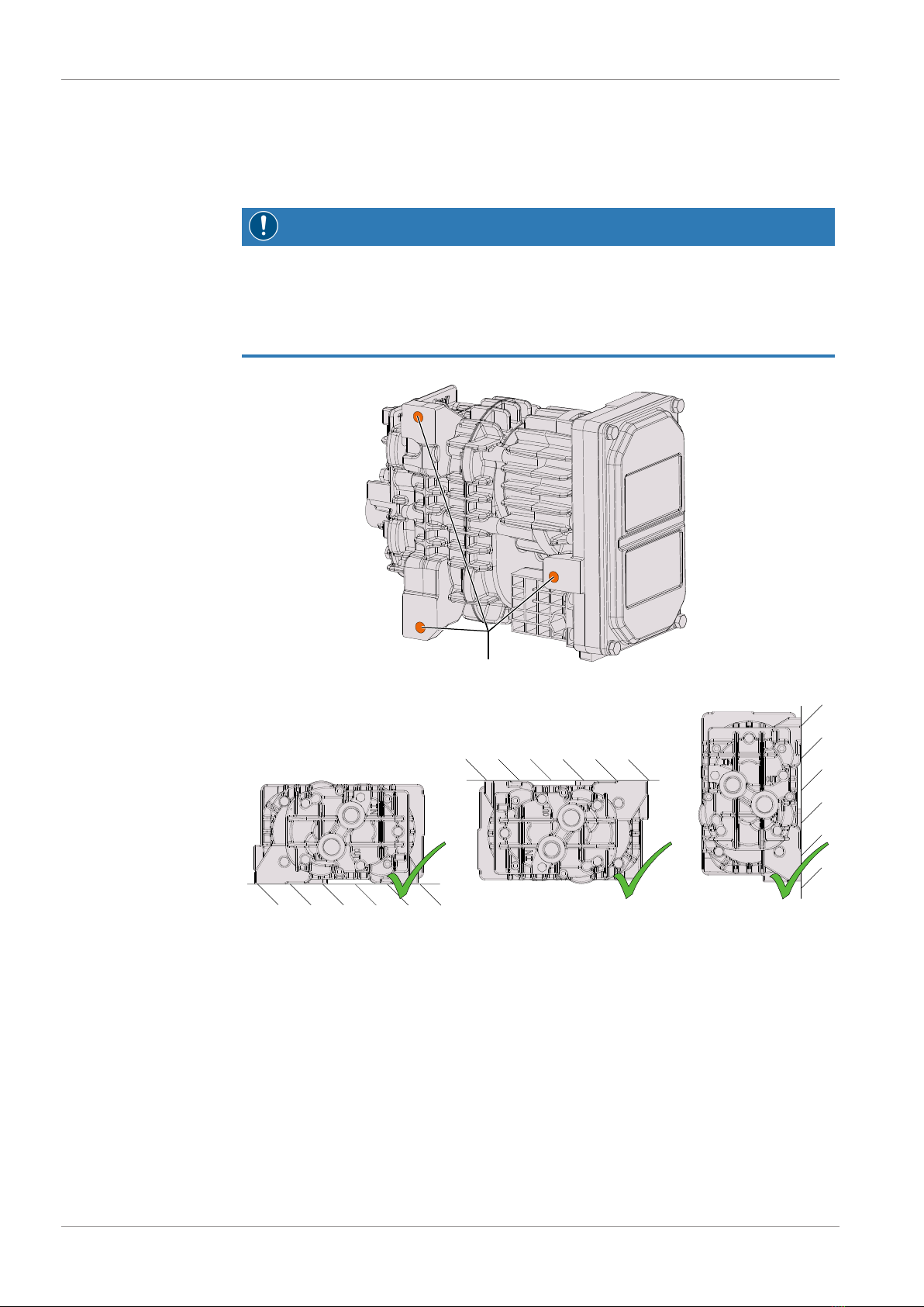
5 Installation................................................................................................................................6
5.1 Installation Conditions...................................................................................................... 6
5.2 Connecting Lines / Pipes .................................................................................................. 7
5.2.1 Suction Connection ............................................................................................... 7
5.2.2 Discharge Connection ........................................................................................... 8
5.3 Electrical Connection ........................................................................................................ 8
5.3.1 Version with Analogue Speed Control ................................................................... 9
5.3.2 Version with CAN-Communication........................................................................ 9
5.3.3 Motor Rotation Direction ...................................................................................... 10
6 Commissioning.........................................................................................................................10
6.1 Standard Version.............................................................................................................. 11
6.2 Version with Analogue Speed Control .............................................................................. 11
6.3 Version with CAN-Communication .................................................................................. 11
7 Maintenance.............................................................................................................................13
7.1 Maintenance Schedule ..................................................................................................... 13
7.2 Oil Draining ..................................................................................................................... 14
7.2.1 Overall Information ...............................................................................................14
7.2.2 Draining Procedure................................................................................................ 15
7.2.3 Service Kit and Oil Type ........................................................................................ 20
7.3 Machine Stage Replacement ............................................................................................ 20
7.3.1 Stage Disassembly .................................................................................................21
7.3.2 Stage Replacement Package ..................................................................................24
7.3.3 Stage Reassembly..................................................................................................24
7.3.4 Stage Testing......................................................................................................... 26
7.3.5 Machine Identification...........................................................................................26
8 Overhaul...................................................................................................................................27
9 Decommissioning.....................................................................................................................27
9.1 Dismantling and Disposal ................................................................................................. 27
10 Spare Parts................................................................................................................................28
11 CAN Protocol............................................................................................................................29
11.1 Standard CAN Interface 250 kBit/s................................................................................... 29
11.2 CAN Interface 500 kBit/s ................................................................................................. 30
11.3 CAN Interface 250 kBit/s, DOT Yellow ............................................................................ 30
11.4 CAN Interface 250 kBit/s, DOT Red................................................................................. 30
11.5 CAN Interface 250 kBit/s, DOT Purple ............................................................................. 30
12 Technical Data..........................................................................................................................32
13 EU Declaration of Conformity...................................................................................................33
14 UK Declaration of Conformity ..................................................................................................34

Safety | 1
0870153444_MA0018A_A0006_IM_en 3 / 36
1 Safety
Prior to handling the machine, this instruction manual should be read and understood. If
anything needs to be clarified, please contact your Busch representative.
Read this manual carefully before use and keep for future reference.
This instruction manual remains valid as long as the customer does not change anything
on the product.
The machine is intended for industrial use. It must be handled only by technically trained
personnel.
Always wear appropriate personal protective equipment in accordance with the local
regulations.
The machine has been designed and manufactured according to state-of-the-art meth-
ods. Nevertheless, residual risks may remain. This instruction manual highlights potential
hazards where appropriate. Safety notes and warning messages are tagged with one of
the keywords DANGER, WARNING, CAUTION, NOTICE and NOTE as follows:
DANGER
... indicates an imminent dangerous situation that will result in death or serious injuries if
not prevented.
WARNING
... indicates a potentially dangerous situation that could result in death or serious injuries.
CAUTION
... indicates a potentially dangerous situation that could result in minor injuries.
NOTICE
... indicates a potentially dangerous situation that could result in damage to property.
NOTE
... indicates helpful tips and recommendations, as well as information for efficient and
trouble-free operation.

2 | Product Description
4 / 36 0870153444_MA0018A_A0006_IM_en
2 Product Description
COM
NP
ECO IN OUT
COM 6-pole HDSCS connector (CAN) ECO Electrical connection (+VBatt)
IN Inlet connection NP Nameplate
OUT Pressure connection
NOTE
Technical term.
In this instruction manual, we consider that the term ‘machine’ refers to the ‘com-
pressor’.
NOTE
Illustrations
In this instruction manual the illustrations may differ from the machine appearance.
2.1 Operating Principle
The machine works on the claw principle.

Transport | 3
0870153444_MA0018A_A0006_IM_en 5 / 36
2.2 Application
The machine is intended for the compression of air and other dry, non-aggressive, non-
toxic and non-explosive gases.
Conveying of other media leads to an increased thermal and/or mechanical load on the
machine and is permissible only after a consultation with Busch.
The machine is intended for the placement in a non-potentially explosive environment.
The machine is suitable for continuous operation.
Permitted environmental conditions, see Technical Data [►32].
3 Transport
Machine weight:
see the technical data or the nameplate
• Check the machine for transport damage.
If the machine is secured to a base plate:
• Remove the machine from the base plate.
4 Storage
• Seal all apertures with adhesive tape or reuse provided caps, if not connected to a sys-
tem.
If the machine is to be stored for more than 2 months:
• Make sure that the inside of the process chamber will be kept dry and dust free at
ambient temperature.
• Before restarting the machine after a long period of machine shutdown, it is re-
commended to maintain as described in chapter Oil Draining [►14].

5 | Installation
6 / 36 0870153444_MA0018A_A0006_IM_en
5 Installation
5.1 Installation Conditions
NOTICE
Use of the machine outside of the permitted installation conditions.
Risk of premature failure!
Loss of efficiency!
• Take care that the installation conditions are fully complied with.
Fixing points
• Make sure that the environment of the machine is not potentially explosive.
• Make sure that the ambient conditions comply with the Technical Data [►32].
• Make sure that the machine surface is clean from dust and dirt to guarantee an effi-
cient cooling.
• Make sure that the installation space or location is vented such that sufficient cooling
of the machine is provided.
• We strongly recommend to install the product at the top level of the fluid circuit to
avoid the stagnation of condensates inside the compression stage.
• Make sure that all provided covers, guards, hoods, etc. are mounted.

Installation | 5
0870153444_MA0018A_A0006_IM_en 7 / 36
WARNING
Vibration level.
Risk of premature failure!
• Make sure the product is protected from external shocks. Regarding vibration level,
please contact your Busch representative to discuss the corresponding levels.
If the machine is installed at an altitude greater than 1000 meters above sea level:
• Contact your Busch representative, the motor should be derated or the ambient
temperature limited.
5.2 Connecting Lines / Pipes
WARNING
Unprotected connection.
Risk of severe injury!
• Do not put hand or fingers in the connection.
• Remove all protective covers before installation.
• Make sure that the connection lines cause no stress on the machine‘s connection; if
necessary use flexible joints.
• Make sure that the line size of the connection lines over the entire length is at least as
large as the connections of the machine.
In case of long connection lines it is advisable to use larger line sizes in order to avoid a
loss of efficiency. Seek advice from your Busch representative.
• Make sure that the connections are “face sealed” and not “thread sealed” to ensure
tightness.
5.2.1 Suction Connection
WARNING
Unprotected connection.
Risk of severe injury!
• Do not put hand or fingers in the connection.
NOTICE
Ingress of foreign objects or liquids.
Risk of damage to the machine!
If the inlet gas contains dust or other foreign solid particles:
• Install a suitable filter (5micron or less) upstream from the machine.
Connection size(s):
– G1/2
Depending on the specific order, other connection dimensions may apply.
• Make sure that the gas is drawn without obstruction.

5 | Installation
8 / 36 0870153444_MA0018A_A0006_IM_en
5.2.2 Discharge Connection
WARNING
Unprotected connection.
Risk of severe injury!
• Do not put hand or fingers in the connection.
Connection size(s):
– G1/2
Depending on the specific order, other connection dimensions may apply.
• Make sure that the discharged gas will flow without obstruction. Do not shut off or
throttle the discharge line.
5.3 Electrical Connection
DANGER
Live wires.
Risk of electrical shock.
• Electrical installation work must only be executed by qualified personnel.
• Make sure that the motor of the machine will not be affected by electric or electro-
magnetic disturbance from the mains; if necessary seek advice from Busch.
• Electrically connect the machine
+V Batt (M8 thread)
-V Batt (M8 thread)

Installation | 5
0870153444_MA0018A_A0006_IM_en 9 / 36
5.3.1 Version with Analogue Speed Control
4
5
6
1
2
3
1 = 0 … 5 V (= 0 … 6600 rpm)
2 = -
3 = -
4 = -
5 = -
6 = -
5.3.2 Version with CAN-Communication
4
5
6
1
2
3
1 = KL15 (20-32VDC)
2 = CAN H
3 = CAN L
4 = +5V supply for Mass Flow Sensor (op-
tional)
5 = SENT for Mass Flow Sensor (optional)
6 = GND for Mass Flow Sensor (optional)
NOTE
If KL15 cable (pin 1 of the CAN connector) and CAN cable are longer than 30 meters.
Risk of electromagnetic disturbances!
• Make sure that the length of each cable does not exceed 30 meters.

6 | Commissioning
10 / 36 0870153444_MA0018A_A0006_IM_en
5.3.3 Motor Rotation Direction
6 Commissioning
NOTICE
Lubricating a dry running machine (compression chamber).
Risk of damage to the machine!
• Do not lubricate the compression chamber of the machine with oil or grease.
CAUTION
During operation the surface of the machine may reach temperatures of more than
70°C.
Risk of burns!
• Avoid contact with the machine during and directly after operation.
CAUTION
Noise of running machine.
Risk of damage to hearing!
If persons are present in the vicinity of a non noise insulated machine over extended
periods:
• Make sure that ear protection is being used.
• Make sure that the installation conditions (see Installation Conditions [►6]) are met.
• Switch on the machine.
• Make sure that the operating conditions comply with the Technical Data [►32].
As soon as the machine is operated under normal operating conditions:
• Measure the motor current and record it as reference for future maintenance and
troubleshooting work.

Commissioning | 6
0870153444_MA0018A_A0006_IM_en 11 / 36
6.1 Standard Version
The machine starts automatically with maximum speed as soon as electrical power is
supplied.
6.2 Version with Analogue Speed Control
The electronic is automatically activated as soon as electrical power is supplied.
The speed can be controlled by a potentiometer connected to terminal 1 (KL15) on the
HDSC connector (CON).
Observe the following diagram to adjust the speed.
6.3 Version with CAN-Communication
The CAN communication and protocol are based on the following standards:
• ISO 11898 for hardware,
• SAE J1939 as vehicle standard for the software.
The CAN address coding is using the Intel protocol with Little Endian format.
The machine is controlled via CAN communication (see CAN Protocol [►29]). The
CAN control message send all necessary signals and reference values to the machine.
There are two different operating modes.
The speed control mode controls the speed of the machine.
The mass flow control mode controls the speed of the machine depending on the mass
flow. For mass flow control mode the machine must be equipped with an air mass flow
sensor. In case of a failure of the air mass flow sensor the machine switches automatic-
ally to speed control mode.
Terminal 1 (KL15)
NOTE
The KL15 must be powered with the same voltage as the +Vbatt (20-32VDC with a
nominal voltage of 24VDC).

6 | Commissioning
12 / 36 0870153444_MA0018A_A0006_IM_en
High voltage level on terminal 1 (KL15) switches on the internal power supply of the ma-
chine. After switching on, the machine waits 10seconds for a valid CAN control message
before a CAN failure will be detected.
In case of a voltage level below 1.2V on terminal 1 (KL15) the machine decelerates to a
speed of 1800 min-1. After 10seconds the machine stops. After further 2.5seconds the
internal power supply of the machine switches off.
CAN Status Message (Actual Values)
One second after startup, the machine sends every 50ms a CAN status message with
actual values. If the machine receives a CAN control message before the first second
after startup the machine sends the CAN status message immediately.
Power-On Bit
After startup a power-on bit is set in the CAN status frame for one second. The power-
on bit can be used to identify unexpected resets/restarts.
Loss of CAN Communication
If a loss of CAN communication occurs the reference value for mass flow will be set to
100g/min. A loss of CAN communication will be detected if no valid CAN control mes-
sage have been received for 500ms. As soon as the CAN communication is available
again the machine switches to normal operation immediately.
Speed reduction by temperature
The maximum speed of the machine depends on the electronic temperature to ensure
safe operation of the machine at any temperatures.
The machine will reduce the speed if the electronic temperature is too high even if the
reference speed value is higher than the actual speed. The speed reduction resulted from
the electronic temperature is indicated by the sixth bit in the CAN status frame. There
will be no indication on the sixth bit if the actual speed limited by the electronic tempera-
ture complies with the maximum speed.
Loss of air mass flow sensor
At loss of the air mass flow sensor, the software switches automatically into the speed
control mode with the predefined speed pre-control value.
Without or in case of loss of air mass flow sensor, the actual air temperature (given by
the CAN Actual Values) is 214°C by default.
The loss of air mass flow sensor is visible in the CAN Status bit (see CAN Protocol). This
failure is automatically reset as soon as new values are received from the air mass flow
sensor. Without air mass flow sensor, the bit 2 of the diagnostics is automatically set to
1.
Over current protection
The electronics is protected against a blocked rotor or overload by an overcurrent protec-
tion. If an overcurrent is detected the motor stops immediately. The bit 7 “overcurrent”
in the CAN Status frame is set for about 2 seconds.

Maintenance | 7
0870153444_MA0018A_A0006_IM_en 13 / 36
One second after the stop of the motor the electronic tries to restart the motor automat-
ically. If the overcurrent error occurs one more time, the motor stops again and the error
bit in the can status frame stays on.
Plausibility check
A blocked rotor cannot be detected under all conditions by an overcurrent detection.
Therefore, an additionally plausibility check is implemented.
The plausibility check checks different ratios inside the motor controller. If a plausibility
check error occur the motor stops immediately and the bit 5 “plausibility error” in the
CAN Status frame is set.
The timing for the error bit and the restart is identical to the overcurrent protection.
Electronics limits
Status and diagnostic Bit number Limit
Wrong voltage 4 24 V motor ► 35 V
Temperature limit 6 130 … 145 °C ► rotation speed de-
crease
>145 °C ► motor off
Overload 6 and 7 700 W
7 Maintenance
WARNING
Machines contaminated with hazardous material.
Risk of poisoning!
Risk of infection!
If the machine is contaminated with hazardous material:
• Wear appropriate personal protective equipment.
CAUTION
Hot surface.
Risk of burns!
• Prior to any action requiring touching the machine, let the machine cool down first.
• Shut down the machine and lock against inadvertent start up.
• Vent the connected lines to atmospheric pressure.
If necessary:
• Disconnect all connections.
• Separate special waste from the machine.
• Dispose of special waste in compliance with applicable regulations.
• Dispose of the machine as scrap metal.
7.1 Maintenance Schedule
The maintenance intervals depend very much on the individual operating conditions. The
intervals given below are considered as starting values which should be shortened or ex-
tended as appropriate. Particularly harsh applications or heavy duty operation, such as
high dust loads in the environment or in the process gas, other contamination or ingress of
process material, can make it necessary to shorten the maintenance intervals significantly.

7 | Maintenance
14 / 36 0870153444_MA0018A_A0006_IM_en
Interval Maintenance work
Every 12000 hours, at the least
after 6 years
• Replace the machine.
7.2 Oil Draining
7.2.1 Overall Information
NOTE
Oil draining.
Recommendation.
• There is no ideal angle to put the gear for oil draining. We would recommend to move
the gearbox several times from standard “vertical position” to a 90° position. The re-
maining oil must be the lowest possible.
• The illustration below shows the internal ribs and explains that there will always
remain some oil inside.
Internal view of gearbox and oil output
• The illustration below shows the “vertical position” for oil refilling.

Maintenance | 7
0870153444_MA0018A_A0006_IM_en 15 / 36
7.2.2 Draining Procedure
NOTICE
Oil draining procedure.
Risk of damage to the machine!
• Before proceeding the oil draining, make sure that the cylinder of your machine has
four access holes to the motor screws. If not, do not proceed the oil draining and con-
tact your Busch representative.
STEP 1
• Remove the machine from the system.
STEP 2
• Use an M5 hexagonal tool to unscrew the four motor screws directly accessible
through the four access holes of the cylinder.
STEP 3
Removing the motor:
• Hold the motor while pulling up the stage (because of the resistance coming from the
rotor’s magnetic force).

7 | Maintenance
16 / 36 0870153444_MA0018A_A0006_IM_en
STEP 4
NOTE
Oil draining.
Recommendation.
• There is no ideal angle to put the gear for oil draining. We would recommend to move
the gearbox several times from standard “vertical position” to a 90° position. The re-
maining oil must be the lowest possible.
1
4
Oil
2
MIN/MAX
3
Oil draining and refilling
Use the new oil filling plug
from the Service Kit
As shown in the illustration above:
• 1. Remove the oil filling plug and drain the oil.
• 2-3. With the machine in vertical position, refill with the new oil until the oil level is
close to the lower edge of the oil draining/filling hole. The amount of oil required to
refill is approximately 90 ml (see Service Kit and Oil Type [►20] for the oil type to
be used to refill).
• 4. Replace the old oil filling plug by the new one from the Service Kit (see Service Kit
and Oil Type [►20] for the service kit part number to be ordered) and tighten it
with a 7 Nm screwing torque.

Maintenance | 7
0870153444_MA0018A_A0006_IM_en 17 / 36
STEP 5
• 1. Check the surface cleanliness for oil traces.
NOTICE
Cleaning the surface.
Risk of damage to the machine!
• Do not use any solvant or liquid. Use only clean and dry paper or tissue!
1
• 2. Remove the existing O-Ring carefully to avoid damaging the groove.
2
• Make sure there is no burr on machined surfaces (chamfer, groove, flange surface,
etc.).

7 | Maintenance
18 / 36 0870153444_MA0018A_A0006_IM_en
STEP 6
• Replace the old motor nose O-ring by the new one delivered in the kit.
Put grease on it then place it correctly in its groove.
2
1

Maintenance | 7
0870153444_MA0018A_A0006_IM_en 19 / 36
STEP 7
NOTICE
Inserting the stage into the motor.
Risk of damage to the machine!
• Take care and make sure not to shock or bump the stage while inserting it into the
motor!
• Insert gently the stage into the motor. Then insert and tighten the four M6 screws
with a 5 Nm (+/-10%) screwing torque.

7 | Maintenance
20 / 36 0870153444_MA0018A_A0006_IM_en
7.2.3 Service Kit and Oil Type
Service Kit
– Part number: 0990221163
– Content: Oil filling plug + Motor nose O-ring
Oil Type
– Fuchs Renolin Unisyn OL32
Oil has to be purchased locally by sales companies because of oil packaging.
Table of contents
Other BUSCH Air Compressor manuals
Popular Air Compressor manuals by other brands

Britpart
Britpart DA2392 user manual

California Air Tools
California Air Tools 10010LFDCAD owner's manual

SHARKS
SHARKS Airstation SHK 476 Instruction for operation and maintenance

Paslode
Paslode C10060 operating instructions

Atmos
Atmos ALBERT E 100 Vario Operation and Maintenance Handbook

KuSh Audio
KuSh Audio TWEAKER Operator's manual

Huvema
Huvema BL 24 AIR instructions

Gude
Gude 400/10/50 N operating instructions

Scheppach
Scheppach HC06 Translation from the original instruction manual

AirMan
AirMan ResQ Pilot user manual

Porter-Cable
Porter-Cable J0B BOSS C3151 instruction manual

Doosan
Doosan XHP1070WCAT-EX-T1 Operation & maintenance manual