Bushranger REVO 10S User manual

REVO 10S | REVO 10W | REVO 12S | REVO 12W

Congratulations on the purchase of your Bushranger vehicle recovery winch. This
product has been designed to meet the specied applications (see limitations
below in ‘Warning’) and with proper care and preventative maintenance will
give you years of trouble-free operation. All information in this publication is based
on the latest production information available at the time of print. We reserve the
right to make changes without notice because of continued
product improvement.
Your Bushranger winch has been designed to give safe and dependable service if
operated according to the instructions. Please read and understand this manual
before installation and operation of the winch. Careless winch operation can
result in serious injury or property damage.
When requesting information or ordering replacement parts, always give the
following information:
1. Winch model and voltage
2. Serial Number
3. Item. No. and Part Number
4. Part Description

Table of contents
Introduction
Warnings & Safety
Installation
Winching Principles
Accessories
Winching Procedures
Maintenance
Troubleshooting
Specications
Parts List
Warranty
1
2
4
11
13
14
21
24
25
29
38
Warnings
Safety
• Before use, ensure that you are familiar with all winching operations (winch speeds
& direction).
• In some cases, the operator of a winch may be required to have qualications
according to applicable laws and ordinances.
• Check all safety and environmental conditions prior to and during use.
• Only use correctly rated rope. Inspect for damage and/or defects before use.
• Do not use an unsuitable hook or snatch block for rope.
• The operator must remain with the winch during operation.
• The winch duty rating is S3 (intermittent-periodic).
• Do not use the winch as a lifting device or a hoist for vertical lifting and
moving people.
• Ensure that the winch is connected to the correct voltage (12VDC only).
• Do not exceed the maximum line pull ratings shown in this manual. Shock loads
must not exceed these ratings.
• Pull from an angle below 15° in the horizontal plane to straighten up the vehicle
or load.
• Always use appropriate gloves when handling the wire rope.
1. It is highly recommended that prior to using this off road vehicle recovery winch,
that users undertake off road training including vehicle recovery. Recovering
immobilised vehicles is a potentially dangerous exercise and this winch is to be used
with great care.
2. The winch is rated at the rst layer of rope on the drum for intermittent
periodic duty.
3. The winch is not to be used to lift, support or otherwise transport personnel.
4. A minimum of ve (5) wraps of steel wire rope and ten (10) wraps of synthetic rope
around the drum is necessary to support the rated load.
5. Keep clear of winch, rope, hook, and fairlead while operating.
6. Rope can break without warning. Always keep a safe distance from the winch and
rope while under a load.
7. Failure to adequately align, support, or attach the winch to a suitable mounting
base could result in a loss of efciency of performance or damage to the winch,
rope and mounting platform.
NOTE: This product is a very powerful machine. Treat with extreme care and observe
all cautions and warnings.
| REVO VEHICLE RECOVERY WINCH |REVO VEHICLE RECOVERY WINCH
Page 1 Page 2

• When winching, always use a recovery damper.
Place over the rope in the middle third of its
length.
• A rope should be replaced if it shows signs of
excessive wear, broken strands, corrosion for
wire rope and excessive abrasion or fused and
melted bre for synthetic rope or any
other defects.
• If the winch fails to pull a load under normal
conditions, manually stop the operation,
otherwise motor damage may occur.
• Check that the clutch handle is in the
“Engaged” position during and after use.
• Remove the remote control from the winch
when not in use and store in a safe, dry place.
• Do not wrap the rope around the load and
back onto itself. Always use a tree trunk or
winch extension strap.
• Keep hands and clothing clear of the winch,
rope, and fairlead opening.
• Never unplug the remote control when
winching a load.
• To avoid insufcient power when winching a
load, the vehicle should be running and
in neutral.
• Keep the remote control clear of the rope at
all times.
• If noise or vibration occurs when operating, stop
the winch immediately and inspect or return it
for repair.
• The rope must be wound in an under-wound
orientation only to ensure correct
brake operation.
• Always inspect the hook, latch and pin prior to
use. Do not use if there are any signs of excess
distortion or bending.
• Ensure the pin of the hook is secured using a
correctly installed split/cotter pin.
Fleet AngleRope
Centreline of anchor point
WRONG FITMENT
CORRECT FITMENT
Overwound
Underwound
Installation
It is highly recommended that installation is performed by an authorised
technician, familiar with this product.
The winch is provided with a range of bolts to suit the different mounting options:
Note: Four (4) M10 x 1.50 pitch 8.8 grade high tensile steel bolts (supplied) must be
used in order to sustain the loads imposed on the winch mounting.
Winch mounting
• It is very important that the winch is mounted on a at and hard surface or
mounting channel or in a suitable winch-compatible bull bar to ensure the motor,
drum and gearbox housing are aligned correctly.
• The fairlead is not designed to mount to the winch directly.
• The rope must be wound in an under-wound orientation only.
• 4 x M10x35mm Hex Head bolts (for foot down installation)
• 2 x M10x50mm Button Head Bolts (for mounting Hawse Fairlead in foot forward
mounting – REVO 10S and 12S)
• 2 x M10x45mm Button Head Bolts (for mounting Roller Fairlead in foot forward
mounting – REVO 10W only)
• 2 x M10x40mm Button Head Bolts (for mounting Hawse & Roller Fairlead in foot
down mounting)
• 6 x M10 Spring Washers
• 6 x M10 Flat Washers
• 4 x M10 Hex Nuts
• 2 x M10 Lock Nuts
Foot Down Installation Foot Forward Installation
Torque Settings (Maximum)
M10 x 1.5 – 8.8 Grade 44 N.m
| REVO VEHICLE RECOVERY WINCH |REVO VEHICLE RECOVERY WINCH
Page 3 Page 4

The Control Box has been designed with multiple mounting options to suit a variety
of mounting locations and orientations. The “Bushranger” stick on label is supplied
loose in your winch kit and should be adhered to the Control Box once a suitable
mounting method has been chosen and the correct orientation is known.
Cable Routing
The control box is supplied with the power cables exiting through the centre
opening on the underside face. The cables can also be routed to leave through
the sides of the control box, which may be more suitable for certain installations. To
re-route the cables through the sides, remove the plastic control box cover and use
a sharp knife or cutters to remove either the left or right hand side cut out section, as
shown. The black contactor unit will need to be removed to allow the cables to be
re-routed through the new opening created in the cover.
Control box mounting
Optional
Side Openings Contactor Unit
Centre Opening
Cut Line
Mounting option 1 - Mounting Bracket
A steel mounting bracket is supplied for applications where the Control Box is to be
installed independently of the winch and requires clearance underneath. To t, rstly
remove the plastic control box cover by loosening 2 screws each side, then align
the steel mounting bracket with the 4 holes in the base plate of the control box. Use
4 x M5 bolts to fasten the bracket to the base, as shown below, then reinstall the
plastic control box cover. Secure the mounting bracket to the mounting surface
using appropriate bolts (not included) tted through the slots in the
mounting bracket.
Control Box Bracket Reinstall coverRemove cover and
secure M5 bolts
Bolt through
to control
Box Bracket
Mounting Option 2 - Directly to winch
The Control Box may be tted to the cross bars of the winch. Remove the plastic
control box cover and align the 4 x holes in base plate with the 4 x threaded holes
in the winch tie bars. Use 4 x M5 bolts to secure the control box to the winch, then
reinstall the plastic control box cover.
Mounting Option 3 - Vertical Mounting
The Control Box may also be tted vertically to a surface. Remove the plastic control
box cover and align the slots in base plate with the holes in the at surface being
mounted to. Use at least 2 x bolts (not included) to secure the control box to the
surface, then reinstall the plastic control box cover.
Remove cover & secure to
winch with M5 Bolts
Remove cover & secure
with appropriate fasteners
Reinstall Cover
Reinstall Cover
| REVO VEHICLE RECOVERY WINCH |REVO VEHICLE RECOVERY WINCH
Page 5 Page 6

Gearbox Rotation
Important note: Important note:
The gearbox end of the winch can be rotated in 22.5° increments to allow for the
clutch handle to be orientated to best suit the installation requirements.
1). Loosen and partially remove the 8 x bolts (see important note and red arrows
below) that secure the two gearbox sections to the winch. DO NOT remove the
gearbox sections from the winch.
2). Rotate the two gearbox sections and bolts simultaneously (all moving parts
highlighted in grey) to achieve the target angle as highlighted below. Ensure the
gearbox seal reseats in the correct position.
3). Reinstall and tighten all bolts to 6Nm with torque wrench.
DO NOT USE Power Tool such as impact driver. This may lead to stripping of bolt
threads and head of socket head bolt.
DO NOT USE Power Tool such as impact driver. This may lead to stripping of bolt
threads and head of socket head bolt.
Motor Rotation
The motor can be rotated to 3 positions in 90° increments to allow for repositioning
of the poles to best suit the installation requirements. These positions are @ 0°, 90°
and 270°.
Loosen and remove the 6 x bolts that secure the motor cover to the drum support.
Remove the motor cover from the winch.
Loosen and partially remove the 2 x bolts that secure the motor to the
drum support.
Rotate the motor to achieve the desired position, ensuring the motor seal reseats
into the correct position. Reinstall motor bolts and tighten to 10Nm torque.
Reinstall the motor cover and tighten the 6 x bolts to 1.5Nm with torque wrench.
1.
2.
3.
4.
ISOMETRIC VIEW
N.T.S.
FLAT PATTERN
.
SCALE
ISOMETRIC VIEW
N.T.S.
FLAT PATTERN
.
SCALE
Battery Recommendations
A fully charged battery and good connections are essential for the proper
operation of your winch. The minimum requirement for a 12 Volt DC battery is 650
cold cranking amps.
| REVO VEHICLE RECOVERY WINCH |REVO VEHICLE RECOVERY WINCH
Page 7 Page 8

Wiring Diagram
Attach the black lead rmly to the negative (–) battery terminal and red lead to
the positive (+) battery terminal. The voltage drop for the winch motor must not
exceed 10% of the nominal voltage of 12V. For best performance, mount the
winch as close to the battery as possible.
For wiring of the wireless receiver on REVO 10S and 12S models, a 2m long red
power wire with inline fuse exits out of the control box and should be connected
to a switched power source. We recommend connection to the vehicles ignition
or accessories circuits, which will allow for the wireless to be used only when the
vehicle is turned on. Another option is to run it through a dash mounted on/off
switch so that the user can turn the wireless function on and off as required.
The nuts on the motor and contactor should be fastened to the s pecied
torqueas outlined in the diagram below. Attempting to fasten the top nut
without locking the bottom nut could result in damage to the studs. Do not
tighten top nut without locking bottom nut.
Nut Fastening for Motor & Contactor
Rope Preparation
Prior to using the rope for the rst time, it must be tensioned onto the drum
under load to ensure a tight and uniform wrap is achieved. A rope that is not
tensioned and wound tightly and evenly prior to use can be permanently
damaged since the outer layers of rope can draw down into the inner layers
leading to binding, pinching or wedging between layers.
One method for tensioning the rope onto the drum is to use the weight of the
vehicle on a slight incline to pull on the rope while spooling in. This can be
achieved by following the steps outlined in the following section “Winching
Procedures” (Page 14). Prior to spooling in under this load, ensure the rope is
pulled out to leave the minimum amount of wraps
| REVO VEHICLE RECOVERY WINCH |REVO VEHICLE RECOVERY WINCH
Page 9 Page 10

Winching Principles
NOTE: Kingsley Enterprises Pty. Ltd. recommend that prior to using this recovery
equipment, users should undertake formal training from an accredited industry body
in winch use and vehicle recovery.
Calculating Fleet Angle
Load Rating
Duty Cycle Ratings
To obtain the best rope service, the direction of pull should be on a horizontal plane
within ±15 degrees and perpendicular to the centreline of the winch drum within ±15
degrees. If the eet angle is larger than the recommended angles, incorrect spooling
may occur, resulting in the rope loading onto one side of the rope drum and possible
damage to the rope or winch.
Load and speed varies according to how
much rope is on the drum. The rst layer
of rope on the drum delivers the slowest
speed and the maximum load. A full drum
delivers the maximum speed and the
minimum load.
For this reason, automotive winches are
rated at their rst layer capacities.
Duty cycle ratings usually specify continuous, intermittent, or special duty (typically
expressed in minutes). The IEC (International Electrotechnical Commission) lists the
following ratings:
All automotive winches are rated at S3 intermittent periodic duty.
• S1 - Continuous duty
The motor works at a constant load for enough time to reach temperature
equilibrium.
• S2 - Short-time duty
The motor works at a constant load, but not long enough to reach temperature
equilibrium, and the rest periods are long enough for the motor to reach ambient
temperature.
• S3 - Intermittent periodic duty
Sequential, identical run and rest cycles with constant load. Temperature
equilibrium is never reached. Starting current has little effect on temperature rise.
FULL DRUM
MAX. SPEED
MIN. LOAD
HALF DRUM
MED. SPEED
MED. LOAD
FIRST LAYER
MIN. SPEED
MAX. LOAD
Required Pulling Force
Your winch must be powerful enough to overcome the resistance caused by an
obstacle, such as moving water, mud, snow, sand or on a steep hill, as well as pulling the
vehicle’s full weight.
As a general guide, you need a winch with a maximum line pull at least 1.5 times greater
than the gross vehicle weight.
There are three factors listed that have inuence on the line pull effect required to
recover the vehicle. The values and calculations in this section are approximate and are
for reference only.
a) Gross vehicle mass (GVM)
b) Type of surface to be traversed
c) Gradient to overcome
In recovery and loading, where the winch is used to pull something, the required pulling
force (RPF) can be calculated according to the formula:
RPF = (Wt X S) + (Wt X G)
For example, if a vehicle weighing 3,000kg is winched up an incline of 100% on a
marshy surface, the above formula would be used as follows:
Note: A gradient of 10% is a rise of one metre in ten metres (Height/Distance).
Where
RPF
Wt: 3,000kg,
= (Wt X S) + (Wt X G)
= (3,000kg X 0.52) + (3,000kg X 0.71)
= 1,560kg + 2,130kg
= 3,690kg of effect required to recover the vehicle.
S: 0.52 G: 0.71
Where: Wt
S
G
= the gross vehicle mass (GVM)
= the type of surface to be traversed
= the gradient to overcome
Surface Type Surface Drag (S)
Metal 0.15
Sand 0.18
Gravel 0.20
Soft Sand 0.22
Mud 0.32
Marsh 0.52
Clay 0.52
Gradient Angle (θ) Gradient (G)
5% 3° 0.06
10% 6° 0.11
20% 11° 0.2
30% 17° 0.3
50% 26° 0.44
70% 35° 0.58
100% 45° 0.71
Gradient
Distance
Height
θθ
| REVO VEHICLE RECOVERY WINCH |REVO VEHICLE RECOVERY WINCH
Page 11 Page 12

Accessories
Snatch Block
Tree Trunk Protector Strap
Recovery Damper
Winch Extension Strap
Bridal/Equaliser Strap
Bow Shackles
A snatch block is an important aid to successful winching and can be used to
increase the pulling power (or mechanical advantage) of a winch, or change the
direction of a pull.
Where a double line pull is used (i.e. where a snatch block is used at the load or
anchor point and the winch rope is connected back to the vehicle), twice the pull
force is applied but the speed of recovery is halved.
One snatch block can be used in an indirect pull where the vehicle is limited due to
unsuitable ground or obstruction. In this instance, the pull on the load is the actual line
pull of the winch.
If more than one snatch block is used, they must be located at least 1m (40″) apart
A tree trunk protector strap is useful for connecting a rope to almost any anchor point but
is primarily designed to prevent a tree from ring barking. The tree trunk protector should
be wrapped around the chosen tree or anchor point as low to the ground as possible
and the two ends brought together and joined with a bow shackle. The bow shackle
then becomes the recovery point to where the rope or extension strap is joined.
A recovery damper is a safety device designed to help eliminate the possibility of injury or
property damage in the event of a rope failure. Placed in the middle third of a live rope,
in the event of the rope breaking, the damper can help absorb the energy in the rope
and reduce the likelihood of injury or damage.
Used when your rope isn’t long enough to reach the recovery anchor point, extension
straps are made from polyester webbing and come in various lengths and load ratings to
suit varying recovery situations.
Designed to spread the load of the recovery across two points on the vehicle requiring
assistance. Can be used in both Snatch Strap or Winching recoveries.
Only bow shackles that are load rated should be used for vehicle recovery. Load ratings
are visible on the shackle and will be in the form of WLL (working load limit) or SWL (safe
working load). The shackles, or any other recovery equipment, used should be sized
correctly for the winching task.
Winching Procedures
Clutch Operation
Familiarise yourself with the clutch operation. The clutch handle either “Engages”
the winch for operation or “Disengages” the winch for free spooling of the rope. The
clutch must always be “Engaged” before operating the winch under power.
Powering Out (No Load)
The unique Proportional Brake in the REVO winch allows for effortless powering OUT
under NO LOAD, with no concern for damage occurring to the brake or motor. In
some circumstances powering out the rope may be quicker and easier than free
spooling by hand.
Powering Out (Under Load)
It is not recommended to power OUT the WITH LOAD for longer than 30 seconds.
Exceeding this time will cause high amounts of wear to the friction brake.
1) To disengage, turn the clutch handle 90° in a clockwise direction to the
“Disengaged” position. The rope can now free spool off the drum.
2) To engage, turn the clutch handle 90° in a counter-clockwise direction to the
“Engaged” position.
3) If the clutch handle cannot be properly locked in the “Engaged” position, rotate
the drum to help the clutch device engage the gear train.
4) Wear appropriate gloves and use a pull strap when guiding the rope off the drum.
5) Never disengage the clutch while the rope is under load. The clutch handle must be
returned to the “Engaged” position before winching.
Important Notes Before Operating the Winch
ISOMETRIC VIEW
N.T.S.
FLAT PATTERN
.
SCALE
ISOMETRIC VIEW
N.T.S.
FLAT PATTERN
.
SCALE
ISOMETRIC VIEW
N.T.S.
FLAT PATTERN
.
SCALE
Engaged Disengaged
| REVO VEHICLE RECOVERY WINCH |REVO VEHICLE RECOVERY WINCH
Page 13 Page 14

Cable-in/Cable-out Operation
Wireless Hand Controller
Pairing of new Wireless Hand Controller
Wired Hand Controller
Connect Winch Hand Controller Cable
to Winch Control Box and to Hand Controller
Operating Procedure
To “Winch - Out”, Press and hold the “OUT” Button
To “Winch - In”, Press and hold the “IN” Button
To stop winching, releasing button.
The above operating procedure is the same for the Wireless
Hand Controller.
Activating Wireless Control
Press and hold the POWER Button ( ) for 3 seconds to
activate the Wireless Control. The WIRELESS light will
illuminate to indicate you are in WIRELESS mode. To turn
off,press and hold the POWER Button ( ) for 3 seconds
untilthe WIRELESS light turns off. The controller is also
equipped with an automatic power off function. If the
hand controller is not operated for 2 minutes it will turn off
automatically to conserve battery power.
The wireless hand controller can also be used in wired
Mode. When the cable is plugged in, the “Wired” light
will illuminate.
In the case of replacing a hand controller unit, or loss of pairing, a new controller
can be paired to the wireless receiver by following the steps below. If the wireless
receiver was previously paired to a hand controller, the previous pairing needs to
be cleared from the receiver memory rst.
Note: The wireless receiver is located in the control box and is usually wired into
the vehicles ignition system or on a separate switch (refer to the wiring diagram
on Page 10). Turn the key or ick the switch to turn the wireless receiver ON or OFF.
ISOMETRIC VIEW
N.T.S.
FLAT PATTERN
.
SCALE
ISOMETRIC VIEW
N.T.S.
FLAT PATTERN
.
SCALE
Pairing the new Hand Controller
Clearing the Receiver Memory
1. Ensure the new wireless hand controller is turned OFF
2. Turn on the new wireless hand controller in wireless mode by pressing and holding the
POWER button ( ) for 3 seconds.
3. Press and hold the “IN” and “OUT” buttons on the new hand controller at the same
time. While continuing to press both buttons, the following process will happen:
1. Ensure that the wireless receiver is turned OFF.
2. Turn on the new wireless hand controller in wireless mode by pressing and holding the
POWER button ( ) for 3 seconds.
3. Press and hold the “IN” and “OUT” buttons on the new hand controller at the same
time. While continuing to press both buttons, the following process will happen:
a. The “WIRELESS” green indicator light and “Wired” red indicator light
will illuminate solidly for 6 seconds.
b. The two indicator lights will then ash slowly.
a. The “WIRELESS” green indicator light and “Wired” red indicator light will
illuminate solidly for 6 seconds.
b. The two indicator lights will then ash slowly for another 6 seconds.
c. The two indicator lights will then disappear for another 6 seconds.
d. The two indicator lights will then start to ash quickly.
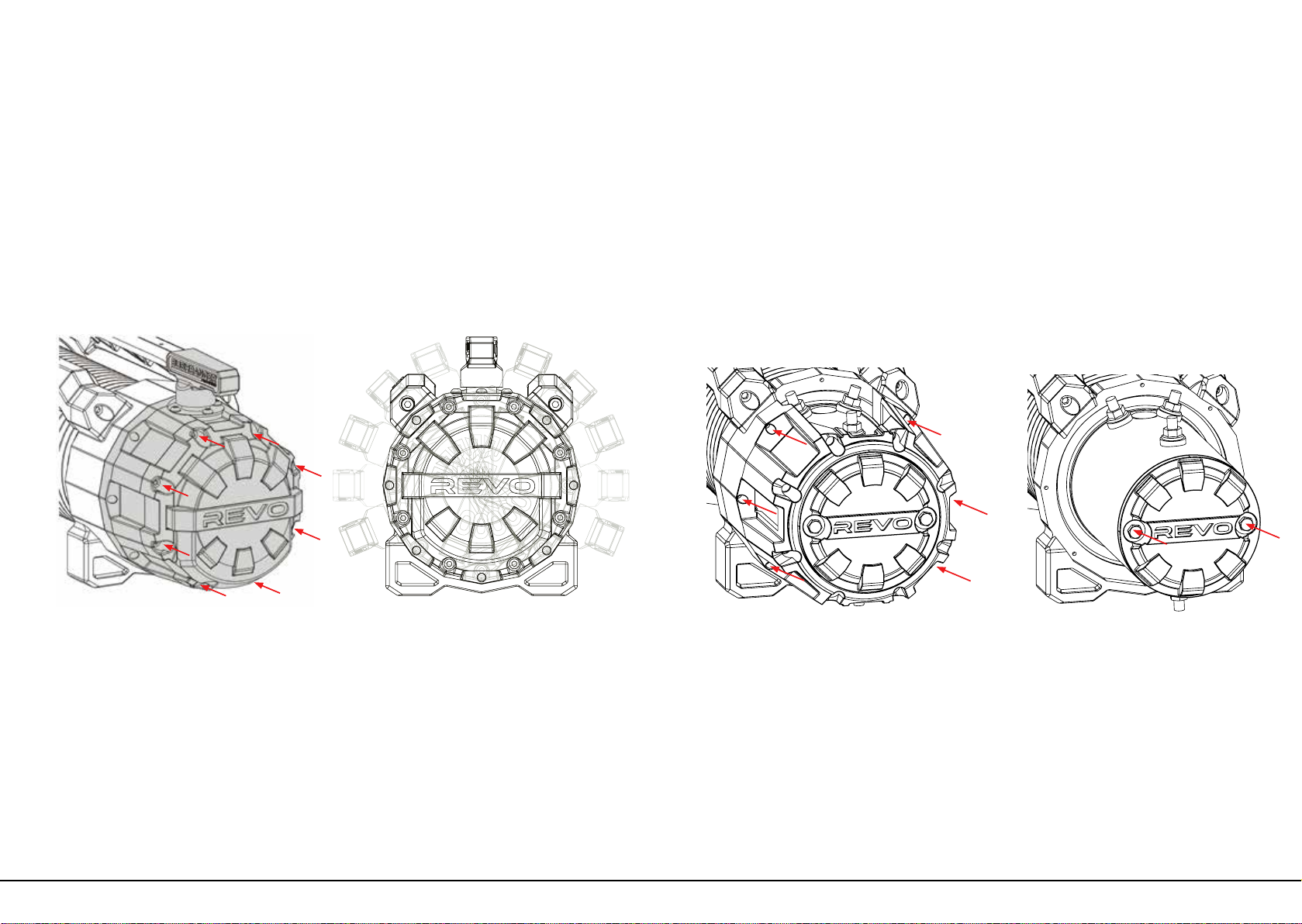
Changing battery in the WIRELESS Hand controller
From the rear of the hand controller, remove the 6 screws as shown below.
Once the screws are removed, the rear half of the hand controller can be separated
allowing access to the battery. Replace the A23 battery and reassemble rear half of
hand controller. When reassembling the hand controller, ensure that the rubber seal is
aligned and not pinched. This will maintain the hand controller waterproof rating.
When the slow ashing begins, continue to hold the ”IN” and “OUT” buttons while
turning ON the wireless receiver. Keep pressing the “IN” and “OUT” buttons until the two
indicator lights disappear. Release the buttons and the hand controller is now paired.
When the quick ashing begins, continue to hold the ”IN” and “OUT” buttons while
turning ON the wireless receiver. Keep pressing the “IN” and “OUT” buttons until the two
indicator lights disappear. Release the buttons and the hand controller is now paired.
| REVO VEHICLE RECOVERY WINCH |REVO VEHICLE RECOVERY WINCH
Page 15 Page 16

Preparation before Winching
Connect each end of the remote
control lead to the corresponding plugs
on the remote control and control box,
ensuring correct alignment. Tighten
collars to ensure reliable connections.
For wireless controller, press and hold
the POWER Button for 3 seconds to
activate controller. Always disconnect
the remote control when not in use.
Wear appropriate gloves when
handling rope. Hold Pull Strap and pull
or power out enough rope to reach the
anchor point. Keep tension on the rope
when unspooling.
Turn the clutch handle in a clockwise
direction to the “Disengaged” position.
The rope is now free to be unwound
from the drum by hand. Never
disengage the clutch while the rope
is under load. Do not disengage the
clutch if powering out in Step 3.
To engage, turn clutch handle in a
counter-clockwise cirection to the
“Engaged” position. Never engage the
clutch while the drum is rotating. The
drum may need to be rotated slightly
by hand to ensure proper engagement.
1) Connect the remote control
3) Pull or Power Out the rope to the
anchor point
2) Disengage the clutch (for freespool
operation)
4) Engage the clutch
ISOMETRIC VIEW
N.T.S.
FLAT PATTERN
.
SCALE
ISOMETRIC VIEW
N.T.S.
FLAT PATTERN
.
SCALE
ISOMETRIC VIEW
N.T.S.
FLAT PATTERN
.
SCALE
ISOMETRIC VIEW
N.T.S.
FLAT PATTERN
.
SCALE
Anchor Point
Winch Operation
When choosing an anchor point, select a rm point such as a tree, stump or
rocks. DO NOT WRAP THE ROPE AROUND THE ANCHOR POINT AND BACK ONTO
ITSELF. Always use a tree trunk protector strap to prevent ring barking the tree and
damage to the rope. If using a winch to retrieve another stranded vehicle, the
rescue vehicle is considered the anchor point and should be made secure. The
anchor point must be strong enough to hold the gross weight of the vehicle and
be positioned to keep the eet angle between the centre of the anchor point and
the wire rope maintained at less than 15°.
Before winching, ensure the rope is
wound on the drum evenly. If unevenly
wound, there is a possibility of damaging
the rope when under load. Visually
check rope for any signs of damage.
Lay a recovery damper or heavy
blanket over the rope in the middle
third of its length. If a rope failure
occurs, the damper can prevent the
rope from whipping.
Use a shackle to lock both ends of the
tree trunk protector and then attach to
the hook.
The recovery vehicle’s engine should be
running to provide maximum power to
the winch. The transmission should be set
in neutral and the hand brake applied to
prevent the vehicle from moving.
1) Check the rope
3) Use a Recovery Damper
2) Attach shackle and hook
4) Prepare Vehicle
| REVO VEHICLE RECOVERY WINCH |REVO VEHICLE RECOVERY WINCH
Page 17 Page 18

Keep tension on the rope to ensure it
winds onto the drum tightly and evenly
and does not sink into the lower layers.
Release Hand brake and continue
pulling until the vehicle is recovered.
Disconnect each end of the remote
control lead from remote control and
control box. For wireless controller,
press and hold the POWER Button for 3
seconds to deactivate controller. Store
remote control in a safe, dry and easily
accessible place.
Once the vehicle is secured, wind the
remaining rope back onto the drum
tightly and evenly and secure the hook
rmly.
5) Begin winching
7) Disconnect remote control
6) Secure vehicle
ISOMETRIC VIEW
N.T.S.
FLAT PATTERN
.
SCALE
ISOMETRIC VIEW
N.T.S.
FLAT PATTERN
.
SCALE
Keep winching area clear. Do not allow
people to remain in the area while
winching. Never step over a live wire
rope whilst under load.
Avoid the remote control lead from
coming in to contact with the winch,
rope or fairlead, as damage to the lead
may result.
Never guide a rope onto the drum with
your hand. Use the supplied Pull Strap.
A winching operation requires extra
consumption of battery power, so
always maintain your battery and
ensure it is in good condition.
Make sure the rope is wound onto the
drum tightly and evenly. Allowing the
rope to become loosely wound can
result in binding, pinching and wedging
between layers, ultimately damaging
the rope, shortening its life and
increasing the risk of injury and failure
under load.
Always keep clear of the winch, rope,
hook and fairlead while winching.
Precautions whilst winching
| REVO VEHICLE RECOVERY WINCH |REVO VEHICLE RECOVERY WINCH
Page 19 Page 20

Maintenance
Always use a replacement rope that is correctly rated for the capacity of the winch.
Use the following method to replace the wire rope:
1. Disengage the clutch handle.
2. Spool out the entire wire rope, loosen the set screw and then remove the rope
from the drum.
3. Feed the replacement wire rope through the roller fairlead opening, pass below
the drum, and insert it into the hole on the drum end. Tighten the set screw to
secure the wire rope.
4. Fit the clevis hook to the thimble end of the rope and ensure the split/cotter pin is
correctly installed to secure the pin.
5. Wind the red section of rope onto the drum tightly and evenly (under hand
tension) to have a minimum of ve (5) wraps of wire rope on the drum.
6. Follow the procedure outlined in the previous sections “Rope Preparation” (Page
10) and “Winching Procedures” (Page 14) to complete the installation of the
replacement wire rope.
7. A minimum of ve (5) wraps of wire rope around the drum is necessary to support
the rated load.
8. A red painted section of the rope warns the operator that there is 3 meters of
rope left on the drum. Do not wind out past this point.
Always use a replacement rope that is correctly rated for the capacity of the winch.
Use the following method to replace the synthetic rope:
1. Disengage the clutch handle.
2. Spool out the entire synthetic rope, loosen the set screw and then remove rope
from the drum and replace the hawse fairlead if necessary.
3. If the end of the rope is not shrink wrapped, cut the lateral side of the end of the
rope at a 45° angle and apply 2-3 wraps of electrical tape to the end to hold cut
strands in place.
4. Thread the rope through the hawse fairlead and under the drum, then insert the
rope all the way through the hole in the end of the drum with 15-20cm protruding
out.
5. Place the protruding section of rope across the drum and tape the end down
to hold it in place. Lightly tighten the set screw to squeeze the rope. Do not over
tighten.
6. Fit the clevis hook to the thimble end of the rope and ensure the split/cotter pin is
correctly installed to secure the pin.
Wire Rope Replacement
Synthetic Rope Replacement
7. Wind the red section of rope onto the drum tightly and evenly (under hand
tension) to have a minimum of ten (10) wraps of wire rope on the drum.
8. Follow the procedure outlined in the previous sections “Rope Preparation”
(Page 10) and “Winching Procedures” (Page 14) to complete the installation
of the replacement synthetic rope.
9. A minimum of ten (10) wraps of synthetic rope around the drum is necessary
to support the rated load.
10. A red painted section of the rope warns the operator that there is 3 meters of
rope left on the drum. Do not wind out past this point.
1. Periodically check the rope for damage or wear. Frayed, kinked or damaged
winch rope must be replaced immediately.
When the rope is used for the rst time, the outer laments may fray. This is
a result of the out laments breaking. The roughened surface will actually
protect the inner bres.
Inspect both inner and outer bres. Open the strands and look for powdered
bre. This is a sign of internal wear.
2. Protect your rope from rubbing against sharp or abrasive objects.
3. An aluminium hawse fairlead with rounded edges is highly recommended for
synthetic rope as it resists damage more easily than a roller fairlead.
4. Keep your synthetic rope clean and dry. To clean it after use in muddy
conditions, spool out the rope, rinse it with fresh water and let it dry completely
before re spooling.
5. All synthetic ropes are affected by UV rays, chemicals, abrasion and
heatOnce the synthetic rope has begun to deteriorate the breaking strength
is compromised. It is recommended that synthetic rope is replaced every 12
months once tted or UV exposed
Tips for Prolonging the Life of Synthetic Rope
| REVO VEHICLE RECOVERY WINCH |REVO VEHICLE RECOVERY WINCH
Page 21 Page 22

Servicing and repairs should only be carried out by an authorised dealer. Unauthorised repairs or servicing will
void warranty. The maintenance scheduled should be followed to ensure reliable operation for the life of the
winch.
The winch should be used regularly to ensure components are kept in good working order. At a minimum, it is
recommended that the rope is powered out and then powered back in on a monthly basis by following the
correct winching procedures (Page 14). The drum support seals are a wearing item and are critical to retaining
the sealed design of the winch. These should be inspected and greased or replaced as required depending on
the frequency of use and the operational environment.
All moving parts in the winch are permanently lubricated at the time of assembly. Under normal conditions,
factory lubrication will sufce. If re-lubrication of the gear box is necessary after repair or disassembly, use Shell
EP2 or equivalent grease. The clutch handle can be lubricated regularly with light oil.
Only use low pressure water to clean the synthetic rope. Do not use any chemicals. We recommend using low
pressure water and a soapy sponge to clean the winch. If high pressure water is used, do not direct it at the
drum area or the clutch handle. Using high pressure water in these areas can force water past seals and lead
to internal water build up which can damage the winch.
Lubrication & Servicing
Cleaning
Maintenance Schedule
1. Ensure that a responsible person carries out all inspections as per schedule.
2. Inspections are divided into Daily, Monthly and Three Months.
Classication of check
Item
Checking
Method Checking Reference
Daily Periodical
One
month
Three
months
OInstallation Mounting bolts &
alignment
Bolt tension &
wear Existence of abnormalities
ORemote
control Correct operation Manual Reasonable actuation
O
Wire rope
Broken strands Visual, measuring Less than 10%
O O Decrease in rope
diameter Visual, measuring 7% of nominal diameter
max
ODeforming or corrosion Visual Existence of abnormalities
OFastening to hook and
drum assemblies Visual Existence of abnormalities
O
Synthetic
rope
Broken strands Visual, measuring Two or more adjacent
strands are cut
O O Decrease in rope
diameter
Visual, measuring 25% of nominal diameter
max
OFused or melted bres Visual Existence of abnormalities
OFastening condition
of end
Visual Existence of abnormalities
OClutch
assembly
Damaged clutch
assembly
Visual evidence
of wear Free of wear or damage
OMotor Staining, damage Visual evidence
of wear Existence of abnormalities
OBrake Ability to hold loads Visual Reasonable actuation
OGears Smooth operation Visual, auditory Reasonable actuation
OSeals Damaged or
worn seals
Visual evidence
of wear Free of wear or damage
Troubleshooting
If the winch fails to operate after several attempts, or if there is any fault
whilst operating:
Wire Rope Replacement
Symptom Possible Cause Remedy
Winch will not
operate
Cut circuit Check battery lead
Weak battery Recharge or replace battery
(at least 650CCA)
Bad connection of wirings Reconnect tightly
Damaged contactor Replace contactor
Cut circuit on switch Replace switch
Damaged motor or worn brushes Replace motor or brushes
Faulty motor wirings Replace wirings
Motor runs
in only one
direction
Broken wirings or bad connections Reconnect or replace wirings
Damaged or stuck contactor Replace contactor
Switch inoperative Replace switch
Faulty wiring Replace wiring
Drum will not
free spool
Clutch does not disengage Engage clutch
Damaged 1st stage shaft Replace 1st stage shaft
Damaged brake Replace brake
Damaged motor output shaft Replace motor output shaft
Brake fails to
operate
The gear train is mechanically
binding up
Check to insure the winch is mounted on
a at, rigid surface
Damaged brake Replace brake
Damaged gear box Replace gear box
Damaged ratchet Replace ratchet components
Braking
distance is too
long
Worn brake Replace brake
Brake jam Proportional mechanism is
damaged or worn Replace
Damaged
gear box
Hit by certain exterior force Replace the damaged components
Damaged gear train Replace the damaged components
Over load operation Stop the winch operation and
reduce a load
Motor runs
extremely hot
Long period of operation Allow to cool
Damaged motor Replace or repair motor
Damaged or inoperative brake Replace or repair brake
| REVO VEHICLE RECOVERY WINCH |REVO VEHICLE RECOVERY WINCH
Page 23 Page 24

216 (8.5")
185 (7.3")
164.9 (6.5")
160 (6.3")
63 (2.5")
227 (8.9")
580 (22.8")
92 (3.6")
254 (10.0")
163.5 162.3
114.3 (4.5")
4 HOLES
11 (0.43")
ISOMETRIC VIEW
N.T.S.
FLAT PATTERN
.
SCALE
REVO 10 Specications
Specications:
Line Pull
Motor 12V
Gear Train
Gear Ratio
Free-spool
Brake
Rope Size
Drum Size
Mounting Bolts Pattern
IP Rating
Winch weight (no rope)
Fitted weight
Gross weight
4536kg/10,000lb
3.9kW/5.2hp
4 stage planetary
171:1
Rotating ring gear
Gearbox Mounted, Proportional Friction Braking System
Synthetic - 10mm x 28m (25/64” x 92’), Wire - 9.2mm x 28m (23/64” x 92’)
63.5mm x 224mm (2.5” x 8.8”)
254mm x 114mm (10” x 4.5”)
IP67
24.5kg/54lb
Synthetic 33kg/73lb, Wire 44kg/97lb
Synthetic 37kg/81.5lb, Wire 49kg/108lb
Performance Specications:
1st Layer of Drum
Pull by Layer - Synthetic Rope Pull by Layer – Wire Rope
Load
(kg/lb)
No load
1816/4000
2724/6000
3632/8000
4540/10000
Layer
1
2
3
4
5
Layer
1
2
3
4
Line Speed
(mpm/fpm)
15/49
3.6/11.8
2.9/9.5
2.4/7.9
1/3.3
kg/lb
4536/10000
3561/7849
2930/6460
2490/5489
2164/4771
kg/lb
4536/10000
3561/7849
2930/6460
2490/5489
Motor Current
(amps)
45
206
270
329
392
Total Rope on Drum
(m/ft)
5.1/16.7
11.4/37.4
18.6/61
26.7/87.6
28/92
Total Rope on Drum
(m/ft)
5.5/18
12.2/40
19.8/65
28/92
| REVO VEHICLE RECOVERY WINCH |REVO VEHICLE RECOVERY WINCH
Page 25 Page 26

REVO 10 Synthetic Model Parts List & Winch Assembly
Item No: Description Qty
1Gearbox End Socket Head
Cap Screw M5*75
8
2 Spring Washer Ø5 26
3Gearbox End Cover 1
4 O Ring Seal 3
5Gearbox Cover Ratchet
Bearing
1
6First Stage Gear Shaft 1
7 First Stage Anti-Wear Washer 1
8Third Stage Sun Gear 1
9 Nut - M12*1.25 1
10 Stop Washer M12 1
11 Ratchet Bearing 1
12 First Stage Ratchet Gear 1
13 Ratchet Gear with Friction
Pad
1
14 Friction Brake Block 1
15 Second Stage Pinion Shaft 1
16 Second Stage Bearing 1
17 Pawl Pin 2
18 Pawl Spacer Bush 4
19 Pawl 2
20 Clutch Cam Cross Pin 1
21 Gearbox Housing Second
Stage
1
22 Wireless Handheld controller 1
23 Bearing Anti-Wear Washer 1
24 Needle Roller Bearing 1
Item No: Description Qty
25 3rd Stage Rotating Ring Gear 1
26 Clutch Pin 1
27 Clutch Pin O Ring Small 1
28 Clutch Pin O Ring Large 1
29 Clutch Cam 1
30 Clutch Spring 1
31 Clutch Handle Socket Cap
Screw M4 x 10mm
1
32 Clutch Spring Washer Ø4 5
33 Clutch Handle 1
34 Clutch Cam Button Head
Cap Screws M4 x 12mm
4
35 Clutch Cam Flat Washer Ø4 4
36 Anti-Wear Washer 1
37 Third Stage Planetary Gear
Assembly
1
38 Third Stage Retaining Circlip 1
39 Third Stage Anti-Wear Washer 1
40 Fourth Stage Planetary Gear
Assembly
1
41 Fourth Stage Gear Ring 1
42 Drum Support Gearbox Side 1
43 Fourth Stage Retaining Socket
Head Cap Screw M5*20
8
44 Input Shaft Bearing 1
45 Winch Mounting Nut M10 4
46 Drum Bearing 2
47 Drum Support Seal 2
48 Shaft Coupler 1
Item No: Description Qty
49 Synthetic Rope 10mm x 28mm 1
50 Motor Output Shaft 1
51 Tie Bar Socket Head Cap
Screw M8*25
4
52 Tie Bar Spring Washer Ø8 4
53 Tie bar 2
54 Contactor Mounting Flange
Nut M5
2
55 Aluminium Hawse 1
56 Control Box Backing Plate 1
57 Contactor Mounting Screws
M6*14
2
58 Control Box Mounting Hex
Head Screw M5*16
4
59 Contactor 1
60 Mounting Board for Wireless
Receiver
1
61 Wireless Receiver 1
62 Control Box Cover Screw
M5*12
4
63 Wireless Receiver Mounting
Screw M3*6
2
64 Control Box Cover 1
65 Control Box Dust Cover 1
66 Control Box Electrical Socket 1
67 Drum Assembly 1
68 Drum Support Motor Side 1
69 Motor Coupling 1
70 10K Motor Cover 1
71 Motor Cover Socket Head
Cap Screw M5x50mm
6
72 10K Motor Assembly 1
Item No: Description Qty
73 Motor End Cover 1
74 Control Box Mounting Bracket 1
75 Synethetic Rope 1/2”Hook 1
76 Spring Washer Ø10 6
77 Flat Washer Ø10 6
78 M10 x 40mm Button Head
Cap Screw (for foot down
mounting)
2
79 M10 x 50mm Button Head
Cap Screw (for foot forward
mounting)
2
80 M10 x 35mm Hex Head Screw 4
81 Hand Strap 1
82 M10 Nyloc Nut 2
83 Motor Mounting Hex Head
Bolts M6 x 160mm
2
84 Flat Washer Ø5 4
85 Remote Control Cable 1
Winch Assembly – REVO 10 Synthetic
| REVO VEHICLE RECOVERY WINCH |REVO VEHICLE RECOVERY WINCH
Page 27 Page 28

Winch Assembly – REVO 10 Synthetic REVO 10 Wire Model Parts List & Winch Assembly
Item No: Description Qty
1Gearbox End Socket Head
Cap Screw M5*75
8
2 Spring Washer Ø5 26
3Gearbox End Cover 1
4 O Ring Seal 3
5Gearbox Cover Ratchet
Bearing
1
6First Stage Gear Shaft 1
7 First Stage Anti-Wear Washer 1
8Third Stage Sun Gear 1
9 Nut - M12*1.25 1
10 Stop Washer M12 1
11 Ratchet Bearing 1
12 First Stage Ratchet Gear 1
13 Ratchet Gear with Friction
Pad
1
14 Friction Brake Block 1
15 Second Stage Pinion Shaft 1
16 Second Stage Bearing 1
17 Pawl Pin 2
18 Pawl Spacer Bush 4
19 Pawl 2
20 Clutch Cam Cross Pin 1
21 Gearbox Housing Second
Stage
1
22 Handheld controller 1
23 Bearing Anti-Wear Washer 1
24 Needle Roller Bearing 1
Item No: Description Qty
25 3rd Stage Rotating Ring Gear 1
26 Clutch Pin 1
27 Clutch Pin O Ring Small 1
28 Clutch Pin O Ring Large 1
29 Clutch Cam 1
30 Clutch Spring 1
31 Clutch Handle Socket Cap
Screw M4 x 10mm
1
32 Clutch Spring Washer Ø4 5
33 Clutch Handle 1
34 Clutch Cam Button Head
Cap Screws M4 x 12mm
4
35 Clutch Cam Flat Washer Ø4 4
36 Anti-Wear Washer 1
37 Third Stage Planetary Gear
Assembly
1
38 Third Stage Retaining Circlip 1
39 Third Stage Anti-Wear Washer 1
40 Fourth Stage Planetary Gear
Assembly
1
41 Fourth Stage Gear Ring 1
42 Drum Support Gearbox Side 1
43 Fourth Stage Retaining Socket
Head Cap Screw M5*20
8
44 Input Shaft Bearing 1
45 Winch Mounting Nut M10 4
46 Drum Bearing 2
47 Drum Support Seal 2
48 Shaft Coupler 1
| REVO VEHICLE RECOVERY WINCH |REVO VEHICLE RECOVERY WINCH
Page 29 Page 30

Item No: Description Qty
49 Wire Rope 1
50 Motor Output Shaft 1
51 Tie Bar Socket Head Cap
Screw M8*25
4
52 Tie Bar Spring Washer Ø8 4
53 Tie bar 2
54 Contactor Mounting Flange
Nut M5
2
55 Roller Fairlead 1
56 Control Box Backing Plate 1
57 Contactor Mounting Screws
M6*14
2
58 Control Box Mounting Socket
Head Cap Screw M5*16
4
59 Contactor 1
60 Mounting Board for Wireless
Receiver
1
- - -
62 Control Box Cover Screw
M5*12
4
- - -
64 Control Box Cover 1
65 Control Box Dust Cover 1
Item No: Description Qty
66 Control Box Electrical Socket 1
67 Drum Assembly 1
68 Drum Support Motor Side 1
69 Motor Coupling 1
70 10K Motor Cover 1
71 Motor Cover Socket Head
Cap Screw M5x50mm
6
72 10K Motor Assembly 1
73 Motor End Cover 1
74 Control Box Mounting Bracket 1
75 Wire Rope 3/8” Hook 1
76 Spring Washer Ø10 6
77 Flat Washer Ø10 6
78 M10 x 40mm Button Head
Cap Screw (for foot down
mounting)
2
79 M10 x 45mm Button Head
Cap Screw (for foot forward
mounting)
2
80 M10 x 35mm Hex Head Screw 4
81 Hand Strap 1
82 M10 Nyloc Nut 2
83 Motor Mounting Hex Head
Bolts M6 x 160mm
2
84 Flat Washer Ø5 4
85 Remote Control Cable 1
Winch Assembly – REVO 10 Wire
| REVO VEHICLE RECOVERY WINCH |REVO VEHICLE RECOVERY WINCH
Page 31 Page 32

REVO 12 Specications
Specications:
Line Pull
Motor 12V
Gear Train
Gear Ratio
Free-spool
Brake
Rope Size
Drum Size
Mounting Bolts Pattern
IP Rating
Winch weight (no rope)
Fitted weight
Boxed weight
5443kg/12,000lb
4.6kW/6.2hp
4 stage planetary
171:1
Rotating ring gear
Gearbox Mounted, Proportional Friction Braking System
Synthetic - 11mm x 24m (7/16” x 78’), Wire - 10.3mm x 25m (2/5” x 82’)
63.5mm x 224mm (2.5” x 8.8”)
254mm x 114mm (10” x 4.5”)
IP67
25.5kg/56lb
Synthetic 35kg/77lb, Wire 48kg/105lb
Synthetic 38kg/84lb, Wire 51kg/112lb
216 (8.5")
185 (7.3")
164.9 (6.5")
160 (6.3")
63 (2.5")
227 (8.9")
602 (23.7")
92 (3.6")
254 (10.0")
180.5 162.3
114.3 (4.5")
4 HOLES
11 (0.43")
Performance Specications:
1st Layer of Drum
Pull by Layer - Synthetic Rope
Load
(kg/lb)
No load
1816/4000
2724/6000
3632/8000
4540/10000
5443/12000
Layer
1
2
3
4
5
Line Speed
(mpm/fpm)
16/52.4
3.2/10.5
2.4/7.9
1.9/6.2
1.5/4.9
1/3.3
Motor Current
(amps)
47
180
230
280
320
420
kg/lb
5443/12000
4195/9250
3413/7525
2877/6343
2486/5481
Total Rope on Drum
(m/ft)
4.2/13.7
9.3/30.5
14.5/47.5
20/65.6
24/79
Pull by Layer – Wire Rope
Layer
1
2
3
4
kg/lb
5443/12000
4195/9250
3413/7525
2877/6343
Total Rope on Drum
(m/ft)
4.7/15.4
10.8/35.4
17.2/56.4
25/82.0
| REVO VEHICLE RECOVERY WINCH |REVO VEHICLE RECOVERY WINCH
Page 33 Page 34

REVO 12 Synthetic Model Parts List & Winch Assembly
Item No: Description Qty
1Gearbox End Socket Head
Cap Screw M5*75
8
2 Spring Washer Ø5 26
3Gearbox End Cover 1
4 O Ring Seal 3
5Gearbox Cover Ratchet
Bearing
1
6First Stage Gear Shaft 1
7 First Stage Anti-Wear Washer 1
8Third Stage Sun Gear 1
9 Nut - M12*1.25 1
10 Stop Washer M12 1
11 Ratchet Bearing 1
12 First Stage Ratchet Gear 1
13 Ratchet Gear with Friction
Pad
1
14 Friction Brake Block 1
15 Second Stage Pinion Shaft 1
16 Second Stage Bearing 1
17 Pawl Pin 2
18 Pawl Spacer Bush 4
19 Pawl 2
20 Clutch Cam Cross Pin 1
21 Gearbox Housing Second
Stage
1
22 Wireless Handheld controller 1
23 Bearing Anti-Wear Washer 1
24 Needle Roller Bearing 1
Item No: Description Qty
25 3rd Stage Rotating Ring Gear 1
26 Clutch Pin 1
27 Clutch Pin O Ring Small 1
28 Clutch Pin O Ring Large 1
29 Clutch Cam 1
30 Clutch Spring 1
31 Clutch Handle Socket Cap
Screw M4 x 10mm
1
32 Clutch Spring Washer Ø4 5
33 Clutch Handle 1
34 Clutch Cam Button Head
Cap Screws M4 x 12mm
4
35 Clutch Cam Flat Washer Ø4 4
36 Anti-Wear Washer 1
37 Third Stage Planetary Gear
Assembly
1
38 Third Stage Retaining Circlip 1
39 Third Stage Anti-Wear Washer 1
40 Fourth Stage Planetary Gear
Assembly
1
41 Fourth Stage Gear Ring 1
42 Drum Support Gearbox Side 1
43 Fourth Stage Retaining Socket
Head Cap Screw M5*20
8
44 Input Shaft Bearing 1
45 Winch Mounting Nut M10 4
46 Drum Bearing 2
47 Drum Support Seal 2
48 Shaft Coupler 1
Item No: Description Qty
49 Synthetic Rope 11mm x 24m 1
50 Motor Output Shaft 1
51 Tie Bar Socket Head Cap
Screw M8*25
4
52 Tie Bar Spring Washer Ø8 4
53 Tie bar 2
54 Contactor Mounting Flange
Nut M5
2
55 Aluminium Hawse 1
56 Control Box Backing Plate 1
57 Contactor Mounting Screws
M6*14
2
58 Control Box Mounting Hex
Head Screw M5*16
4
59 Contactor 1
60 Mounting Board for Wireless
Receiver
1
61 Wireless Receiver 1
62 Control Box Cover Screw
M5*12
4
63 Wireless Receiver Mounting
Screw M3*6
2
64 Control Box Cover 1
65 Control Box Dust Cover 1
66 Control Box Electrical Socket 1
67 Drum Assembly 1
68 Drum Support Motor Side 1
69 Motor Coupling 1
70 12K Motor Cover 1
71 Motor Cover Socket Head
Cap Screw M5x50mm
6
72 12K Motor Assembly 1
Item No: Description Qty
73 Motor End Cover 1
74 Control Box Mounting Bracket 1
75 Synethetic Rope 1/2”Hook 1
76 Spring Washer Ø10 6
77 Flat Washer Ø10 6
78 M10 x 40mm Button Head
Cap Screw (for foot down
mounting)
2
79 M10 x 50mm Button Head
Cap Screw (for foot forward
mounting)
2
80 M10 x 35mm Hex Head Screw 4
81 Hand Strap 1
82 M10 Nyloc Nut 2
83 Motor Mounting Hex Head
Bolts M6 x 160mm
2
84 Flat Washer Ø5 4
85 Remote Control Cable 1
Winch Assembly – REVO 12 Synthetic
| REVO VEHICLE RECOVERY WINCH |REVO VEHICLE RECOVERY WINCH
Page 35 Page 36
This manual suits for next models
4
Table of contents
Other Bushranger Winch manuals
Popular Winch manuals by other brands

ewincher
ewincher ewincher 2 user manual

Comeup
Comeup CP-200 Assembly

GEBUWIN
GEBUWIN WW250 D/Ex Series operating instructions

Champion Power Equipment
Champion Power Equipment 13050 Owner's manual & operating instructions

Champion Power Equipment
Champion Power Equipment T-P2500 Assembly & operating instructions

Quadratec
Quadratec Q-Performance Stealth Series Assembly and installation manual