Butterfly AMICUS ADVANCE User manual

1
TABLE TENNIS ROBOT AMICUS ADVANCE
OPERATION MANUAL
From novice to professional, from defender to attacker,
... ideal for every type of player and every level of play
IMPORTANT: Please read instructions carefully prior to use!
Congratulations, you are now the owner of a
Buttery table tennis robot.
The manufacturer oers a full 2 year gua-
rantee as well as a 5 year service plan cover-
ing repairs and replacement parts, eecti-
ve from the date of purchase. Please ensure
you keep your receipt!
Special features:
• Unique worldwide innovation: Ball delivery
with state of the art three-wheel technology
• The wheels are manufactured using rigid
sponge with a special coating for better
durability
• Compact, solid, functional construction (6kg)
• A large all-round collection net
• Well designed and user-friendly control panel.
• Variable ball placement, adjustable to
desired spin, speed and trajectory
• Programmed and random delivery of balls
with dierent spin, speed, direction and
trajectory
• Automatic correction of length of ball
delivery
• All functions adjustable from the player’s
side on the control panel
• Adjustable height of ball delivery
• Memory space for 22 exercises and AFC
(automatic Frequency control) function
• 10 pre saved exercises selected by
Richard Prause (see page 5)
Please note:
• Please read this instruction manual
carefully before using the machine!
• The Table Tennis Robot may only be
connected to a 100-230V power supply
• The projection wheels rotate at high
speed, therefore avoid touching the
wheels while the machine is running as
this can cause injury!
• The Table Tennis Robot,
AMICUS ADVANCE, should only be
used in closed and dry rooms!
1. Assembly p.2
2. Control Panel (Quick Reference Guide) p.3
3. Operation p.4
3.1 Starting the robot p.4
3.2 The height of the projection head p.4
3.3 Ball Placement p.4
3.4 AFC function p.4
3.5 Memory p.4
3.6 Pre-saved exercises p.5
4. Maintenance and Repair p.6
5. Error Management p.7
6. List of Replacement Parts p.7
7. Technical Data
Further developing steps p.7

2
The following components are included with
the robot and must either be assembled or
connected to the machine prior to its use.
a) Base unit with collection net
b) 24V DC power adapter
c) Control unit
d) Extension cable
e) Control unit holder
Other components: Allen keys, projection
wheels, tube for wheel adjustment, spare
rubber for the collec-tion net, Velcro strips
for securing the collection net.
1. Place the base unit on the table in an
upright position (connections facing you).
(Fig.1.). Open out the net supporting frame
into Position 1. (Fig. 2); the metal poles facing
you are for securing the base unit to the table
as seen in the photograph.
2. Attach the base unit to the table with the
aid of the preassembled holder (see photo-
graph) and rotate the head by loosening the
large screw on the base unit, turning it in the
opposite direction (180 degrees).
3. Standing behind the machine, fold down
the net supporting frame completely by grip-
ping the top part of the frame on each side
and pulling the sides apart until fully exten-
ded (Fig. 3.) Attach the plastic corner pieces
to the corners of the table (Fig. 4.)
4. Then pull the ends of the ball collection
net between the table tennis net posts and
its supports, and secure the rubber bands to
the clamp screws.
Secure the velcro strips, which are attached
to the side of the ball collection net, to their
counterparts xed to the plastic corner
pieces.
5. Connect the extension cable and the adap-
ter to the appropriate connections found on
the side of the base unit (Fig.7). The cable on
the opposite side of the table is then connec-
ted to the control unit which you should then
mount onto the players-side of the table.
(Fig. 8.)
1. ASSEMBLY
1
2
3
5
7
4
6
8

3
Rotary switch
for setting ball
frequency
With the help of rotary switches 1-6 above and the buttons, it is possible to program six dierent landing spots, for example Ball 1
* middle, Ball 2 * left, Ball 3 * right, Ball 4 * right … See illustration.
Trajectory: Trajectory regulation
Button A: Setting balls 6-1
Button B: Setting balls 1-6
Memory: Saving rallies and exercises
Side-Spin: Sidespin regulation (left gSidespin left; 0 gno Sidespin;
right gSidespin right)
Speed: Speed regulation (1 gslow; 19 gfast)
Spin: Spin regulation (-4 gextreme backspin; 0 gno spin; 5 g
extreme topspin)
Memory Place: Choice of up to 10 previously saved exercises (Banks
1-10) and space for up to 12 individually created exer-
cises
Ball/min: Regulation of the ball frequency (balls/min), When set to
0, robot switches to„silent mode”(silent standby)
RND: Choice of two random functions
AFC: Automatic frequency regulation when playing with
varied spin
Backstep: Automatically uses the setting for the previous ball for
the next ball to be set
Sample: Simulates a ball delivery without saving it
2. CONTROL UNIT SHORT DESCRIPTION
Advise: When executing an exercise star-
ting with service, both the trajectory and
speed of the ball are to be adjusted in low
position, whereas the height of the head in
rather high position.
Help buttons for
the settings
Buttons for
regulating sides-
pin and display
Button for Ran-
dom function
and display
LEDs
Buttons for
regulating speed
and display
Buttons for
regulating spin
and display
Rotary switch for
selecting
memory place
Button for AFC
and display
LED
button for
selecting memory
and for saving
Up and down
button for setting
ball trajectory
1-6 rotary
switches
left/right
Button A
1-6 yellow LEDs
for showing the
selected balls Button B

4
Note: During play, only the trajectory can
be changed.
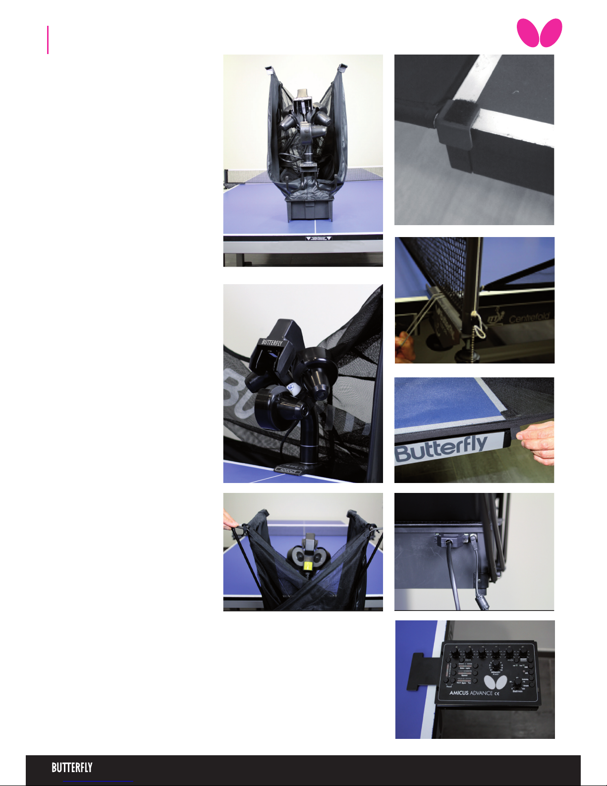
Fill the „ball container” with a sucient quan-
tity of balls (50-60 balls) and then turn the Ball/
min rotary switch to the „0” position before
turning on the power.
After turning on the power, the robot will carry
out a brief self test (approximately 5 seconds)
and the control unit will then automatical-
ly switch to the basic setting. By turning the
„Ball/min” rotary switch to a higher position
the projection motors will start to work and
the robot will start releasing balls.
3. OPERATION
3.1 | STARTING THE ROBOT
3.2 | THE HEIGHT OF THE PROJECTION
HEAD
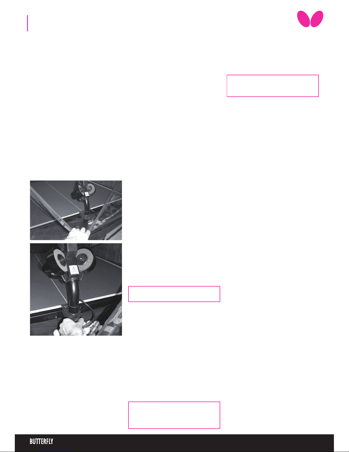
As with all the Amicus robots, the height of the
robot head can be adjusted as follows: Loo-
sen the hand screw on the back of the tube
which holds the projection head. The tube can
be moved up and down as required. (Fig. 9.).
Finally adjust to the desired height, ensuring
that the top of the outer tube lines up with
one of the markings on the inner tube then
tighten the hand screw (Fig. 10).
3.3 | BALL PLACEMENT
Note: This function was developed based
on the fact that fast balls are generally re-
turned quickly whilst returns of slow and
shorter balls require more time.
The new “AFC” (Automatic Frequency Control)
function can be selected if there are dierent
types of balls selected within an exercise.
When the AFC function has been selected the
ADVANCE automatically adjusts the time in-
ter-vals between individual balls with varied
spin.
This function takes into consideration whether
the previous ball was delivered fast or slow
and with backspin or topspin. It can therefore
simulate a real match situation by delivering
the next ball earlier or later accordingly.
3.4 | AFC FUNCTION
1. Ball delivery to a specic point on the table
After turning on of the robot, the rst yellow
light is ashing and the control unit will auto-
matically switch-to the basic setting. The para-
meters of this ball (Trajectory, Sidespin, Speed
and Spin) can be changed with the help of the
buttons for setting the trajectory, sidespin,
speed and spin. The landing spot can be con-
tinuously set using the rotary switch for left/
right placement.
Pushing the “Sample” button the machine gi-
ves an actual ball (one that is set momently)
during the setting procedure.
2. Programmed ball delivery to various points
on the table
With Button B„g“, at least two balls (maximum
six) must be selected. Then various targets can
be chosen by means of the corresponding
left/right switches. The ashing LEDs indicate
which ball will be delivered next. By pressing
Button A „f“ the number of balls can be re-
duced. After the end of each “round” the ball
delivery will commence again from the begin-
ning.
3. “rnd”Random ball delivery to various points
around a specic point
In case the rnd is switched on with the But-
ton for random function (RND) then the ro-
bot plays the set rally (described above) but
not exactly to the set places, but to 20 cm big
sur-rounding of those, which is closer to the
real game. Do not set the ball placing to the
edge of the table when using the„rnd”, becau-
se the machine can throw the balls near the
table by reason of the ball spread!
(It is enough the assigned one ball to this fun-
ction.)
4. “RND” Random ball delivery to various
points on the table
In case switching on the Rnd (pushing ones
more the RND button) the machine doesn’t
throw anymore the set balls in their set order,
but in random way, jumping here and there
among the designated balls. Therefore it can
not be foreseen where the robot throws the
next ball. It is sure only the fact that the balls
are thrown to one of the set places.
(There need to be at least 2 assigned balls to
use this function.)
5. Combining„trnd” and „rnd”
The “trnd” and “rnd” functions can be com-
bined by pressing Button RND for a third time.
In this case the set points are chosen at ran-
dom (RND) and the balls will be de-livered ran-
domly within a 20cm diameter circle of the set
points, simulating a real match situation.
9
10
Programming sequences and exercises takes
time. In order not to lose the programmed
exercises after the robot is switched o, AMI-
CUS ADVANCE allows to save up to 22 exerci-
ses that can be played at any time.
Saving exercises in the memory
Turn the “MEMORY place” rotary switch to the
position where you want to save the exercise
on the control unit (places 11-22). Hold down
the “MEMORY Select/save“ button (approx. 2
secs) until the light starts to ash. The ashing
LED means that the exercise has been saved in
the memory.
Retrieving the saved exercise from the memory
First select the program you require by tur-
ning the “MEMORY place” button accordingly.
By quickly pressing the“MEMORY Select/save“
button, the program number will now appe-
ar on the control unit to which the switch is
currently pointing. All the lights will now start
ashing, indicating that the robot is operating
in memory mode and is now ready to play the
exercise from the memory. Turn the„Ball/min”
rotary switch to start the exercise. The only
settings which can now be adjusted are: “Ball
placement”, „Ball/min”, „AFC” and „RND”. It is
not possible to change the parameters of the
other ball settings.
3.5 | MEMORY
Changing programs in the Memory
It is possible to change the ball sequences
in the programs which have previously been
saved by using the „Backstep” button. This
should be activated for the specic ball which
you would like to adjust within the program
which has just been retrieved from the memo-
ry.. After changing a ball´s settings, the pro-
gram can now be saved again in the memory
by pressing the„MEMORY select/save”button.
Ball characteristics
The set Spin, Speed, Side-Spin and trajectory
apply for each programmed ball in the same
way.
Ball-frequency
By turning the „rotary switch for ball-frequen-
cy“ you can adjust the quantity of ejected balls
per minute.
The AMICUS throws more balls out if the fre-
quency is set higher.
Switch o
Disconnect the power supply when the robot
is not used for a longer period of time;
the AMICUS should never be left alone swit-
ched on.
Note: Memory Banks 1-10 contain pre-
saved exercises that should not be over-
written.

5
Note: Short balls should be returned with
a ick, half – long balls with topspin. More
exercises with Videos can be found in the
ocial Buttery APP for android and iOS.
To start the exercises, simply turn up the
ball / min knob.
Position Ball 1 Ball 2 Ball 3 Ball 4 Ball 5
1 Forehand Forehand Backhand Backhand
2 Backhand mid-table Backhand Forehand Forehand
3 Forehand mid-table Forehand Backhand Backhand
4 Backhand mid-table Forehand
5 Forehand Forehand Backhand
6 Backhand Backhand Forehand
7 mid-table Forehand mid-table Backhand
8short Backhand long Backhand
9 short Forehand long Forehand
10 short mid-table long mid-table
LEFTHANDED
Position Ball 1 Ball 2 Ball 3 Ball 4 Ball 5
1 Backhand Backhand Forehand Forehand
2 Forehand mid-table Forehand Backhand Backhand
3 Backhand mid-table Backhand Forehand Forehand
4 Forehand mid-table Backhand
5 Backhand Backhand Forehand
6 Forehand Forehand Backhand
7 mid-table Backhand mid-table Forehand
8short Forehand long Forehand
9short Backhand long Backhand
10 short mid-table long mid-table
RIGHTHANDED
3.6 | PRESAVED EXERCISES

6
Please note: The correct distance between
the wheels should be 36-37 mm.
4. MAINTENANCE AND REPAIR
Important: Always unplug from the mains
before carrying out any maintenance or
repairs!
• Ensure that whilst operating the robot
small objects such as hair and broken balls
etc do not nd their way into the collecti-
on net and subsequently into the machine,
because this can lead to ball jams.
• The ball projection wheels are very durable and
will last for at least 500 hours. Never-theless, these
wheels will nally wear o after intense use. One
sign for a worn wheel is that the machine releases
the balls at irregular lengths at high speed. This
means that the surface of the wheels does not
have enough grip on the balls. For that rea-son,
the distance of the wheels has to be adjusted.
• To do this rst remove the adjustable plastic
tube from its holder which can be found between
the projection wheels (Fig. 11.). First loosen the
black adjusting screw next to the protective co-
ver of the lower motor (Fig. 12.) with the bigger
allen key provided with the accessories. Push the
motor up towards the adjustable tube, gripping
its cover, until the wheels touch the tube. (Fig. 13.)
Repeat this for the two upper mo-tors.
• If the distance can no longer be adjusted, the
ball projection wheels have to be re-placed.
Therefore loosen the screws (Fig.14.) located
in the wheel mounts using the smaller allen
key provided among the accessories; this ap-
plies to all three wheels. Now remove the “ad-
justing screws” on the two upper motors (it is
not sucient just to loosen them) (Fig. 15.)
Then rotate the two upper motors away from the
projection hole. Grip the outer casing to enable
the removal of the projection wheels from the
axis of the motor. (Fig. 16.)
The plastic disc can now be removed from the
motor shaft. (Fig. 17.a, b,) Remove the plastic
disc from the projection wheel (which is held
together by three screws) and replace it with
a new one.
Slide the new wheel onto the end of the axis
and tighten the screw. Then adjust the correct
distance of the wheels with the help of the ad-
justable tube as described above.
• If a ball jam should occur, the machine will
try to remove the jam automatically by tur-
ning the motor and the projection wheels
backwards and forwards (7-8 times). Should
for any reason the feeding motor and both
projection motors jam at the same time, the
machine will stop to prevent any damage to
the motors. In this case, all six yellow lights
will start to ash on the control unit. You will
have no alternative but to remove the head
from the machine together with any damaged
balls located in the bottom sec-tion of the ro-
bot with the aid of a pencil or screw-driver, etc.
(Fig. 18)
14
11
12
13
15
16
17
17b
18

7
PROBLEM SOLUTION
The robot does not function once assembled. a) No power supply?
b) Blown fuse greplace the fuse in the control unit
c) Check whether the cable plugs on the bottom of the control unit have been plug-
ged in correctly. When the small green control light found on the adapter is not lit,
despite being connected to the mains, this means that the adapter is damaged and
has to be replaced. Is Rotary Switch V for ball frequency set to„0“? gTurn it up.
Length of ball delivery is irregular a) Check distance between the pro-jection wheels, are the wheels worn?
b) Incorrect assembly: Are the tubes and the robot head securely in place?
c) The pin for regulating the length“is stuck”==> lubricate it with some sili-cone
The balls are suddenly being delivered irregularly and
with varying length.
a) Restart
b) A damaged ball or other foreign body is obstructing the transport of balls to the
projection wheels. gremove. The silver sign found on the tube of the robot head
was not put exactly to the top margin of the body tube. Put of the signs exactly to
the top margin of the tube!
Ball jam; the yellow light is ashing on the control unit A damaged ball or foreign body is ob-structing the transport of balls to the projecti-
on wheels g remove.
Random function (RND) on the control unit cannot be
activated; green indi-cator light does not light up.
At least two balls must be activated and at least two yellow indicator lights must be
on.
Balls are stuck between the ball pro-jection wheels, the
control unit switches itself o.
Pull out the adapter from the mains, remove all balls from between the projection
wheels, set the Ball/min button to the“0” position, then re-sume play.
5. ERROR MANAGEMENT
mobil -100 Base unit with collection net
mobil -101 Robot head
ADVANCE -102 Control unit
mobil -103 Holder for control unit
mobil -104 DC adapter (24V; 2,5A)
mobil -105 Extension cable
mobil -106 Projection motor
mobil -107 Feeding motor
mobil -108 Oscillating head motor
mobil -109 Motor for height adjustment
mobil -110 Projection wheel
mobil -111 Axis for projection wheel
mobil -112 Ball placement mechanism
mobil -113 Motor casing (3 pieces)
Further replacement parts on demand!
Mains Power Supply: 100-230V, 50-60 Hz transformer, approximately 40 W
The robot should only be operated indoors within a temperature range of 0-40°C.
Weight: 6 kg (with net). Overall dimensions (with net): Height 0.75m; Width 0.28 m; Depth 0.25 m
The electrical adapter device was subject to a test for the approval of electrical appli-ances
and was found to conform to the standard outlined below:
Conformity with the Low Voltage directive 73/23/EEC
As last amended by EEC Directive 93/68/EEC
Registration No.: AN 50091861 0001
Report No.: 17004848 001
As is evident from Test Report
Nos. NTEK-2010NT1115351E
and NTEK-2010NT1115353SS
The robot AMICUSADVANCE is perMid-tabled to bear the CE trademark.
Further product information and the product video are available on
buttery.tt/amicus
6. LIST OF REPLACEMENT PARTS 7. TECHNICAL DATA
Tamasu Buttery Europa GmbH · Am Schürmannshütt 30h
GERMANY · 47441 Moers · Tel: +49 2841 9053223
amicus@buttery.tt · www.buttery.tt www.facebook.com/butterfly.europe
Attention: If you are not able to resolve the problems with the help of this checklist, a speci-
alist must be consulted! Please contact your specialist supplier or the Buttery service centre
(address is located on the side). Always contact a competent specialist if the power cable is
defective or if the fuse blows again immediately after being replaced. Failure to do so will
invalidate your claim for a refund during the two year guarantee period
14
Pin for regulating the length
Table of contents
Popular Accessories manuals by other brands

Chef's Choice
Chef's Choice EdgeSelect 120 user manual

Pro-tec
Pro-tec 6000PLUS/HT/TS Installation and service instructions

wattstopper
wattstopper PW-103N installation instructions

HAMPTON BAY
HAMPTON BAY HB-27102-03 Use and care guide

Heath Zenith
Heath Zenith Decorative Wireless Chime 6180 owner's manual

d & b audiotechnik
d & b audiotechnik E6530 Mounting instructions