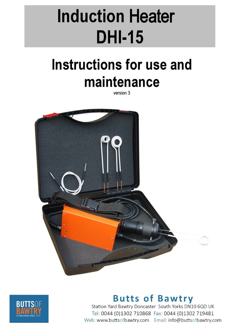
Butts of Bawtry DHI0044 Operating instructions

www.buttsofbawtry.com Tel: 01302 710868 info@buttsofbawtry.com
2
1 INTRODUCTION ............................................................................................................................... 4
2 SAFETY INSTRUCTIONS .................................................................................................................... 4
2.1 GENERAL USE WHEN USING DHI0044 .................................................................................... 4
2.2 INFORMATION SYMBOLS ........................................................................................................ 5
2.3 SYMBOLS INDICATED HEALTH RISKS ....................................................................................... 6
2.4 SYMBOLS WARNING WHILE HANDLING THE DEVICE.............................................................. 7
3 PERIODIC INSPECTION AND MAINTENANCE ................................................................................... 8
4 STORAGE.......................................................................................................................................... 8
5 WARRANTY PROVISION................................................................................................................... 8
6 COMMISIONING .............................................................................................................................. 9
6.1 UNPACKING AND FIRST START ................................................................................................ 9
6.2 COOLANT REFILLING.............................................................................................................. 10
7 REPLACEABLE HEATING INDUCTOR EXTENDERS........................................................................... 10
7.1 HEATING INDUCTOR EXTENDER REPLACEMENT PROCEDURE.............................................. 10
8 ABOUT THE DEVICE AND HEATING ............................................................................................... 10
8.1 SUPPORTED TECHNOLOGIES ................................................................................................. 10
DHCS3 - Heating Control System 2............................................................................................... 10
DIPA - Dynamic Induction Power Adjust ....................................................................................... 11
8.2 HEATING MODES AND THEIR APPLICATION.......................................................................... 11
8.3 CONTROLLED HEATING ......................................................................................................... 12
Using the heating timer................................................................................................................. 12
9 DEVICE CONTROLS......................................................................................................................... 12
9.1 DESCRIPTION OF DEVICE COMPONENTS............................................................................... 12
10 ACTIVATING THE DEVICE ........................................................................................................... 13
11 STANDBY.................................................................................................................................... 14
12 HEATING TIMER......................................................................................................................... 14
13 LIST OF ERRORS MESSAGES....................................................................................................... 15
14 TECHNICAL PARAMETERS.......................................................................................................... 15
15 ELECTRIC SCHEME ..................................................................................................................... 16
16 DECLARATION OF CONFORMITY ............................................................................................... 16
17 SAFETY SHEET OF COOLANT LIQUID.......................................................................................... 17
18 USED DEVICE DISPOSAL............................................................................................................. 21
19 SPARE AND CONSUMPTION PARTS........................................................................................... 21
20 QUALITY CERTIFICATE................................................................................................................ 22
21 WARRANTY SERVICING.............................................................................................................. 22

www.buttsofbawtry.com Tel: 01302 710868 info@buttsofbawtry.com
4
Dear Customer, thank you for your trust and Purchase of this DHI0044 Water Cooled induction Heater.
We believe that you will be fully satisfied with the product for many years to come.
In case of any questions or comments do not hesitate to Contact us either on on our website or Contact
your sales representative directly.
The firstuse of the device is the purpose of this legal step instructions, which the user confirms their free
will, that this instruction properly studied, fully understand itsmeaning andfamiliar with all the risks.
ATTENTION! Do notattempt toplace (or use) the Equipment before you become familiar the entire
operating instructions. Keep the instructions for future use.
2.1 GENERAL USE WHEN USING DHI0044
Symbols shown in this Manual warn and identify potential hazards when handling the device.
-Do not leave DHI0044 unattended while itisturned on. Always deactivate the unit by the master
switch when not using it for heating!
-Make sure that the power supply unit has sufficient air supply for cooling
-Make sure that the ventilation openings are clean andfree ofdust anddirt, tonot preclude flow of cooling
air.
-Do not attempt torepair your inductor - The device contains nouser-reparable components .
-The user is responsible for the system installation anduse in accordance with instructions shown in this
Manual. The supplier is not liable foranydamage due to inexpert use and operation.
-Only persons older than 15 years,properly trained and with adequate qualification can operate the
equipment. Donotusethe equipment when under the influence ofdrugs, alcohol ormedication.
-Keep persons standing around and animalsat a safe distance while working with the device, including
while the heated material iscooling down.
-Avoid working in rain,water and humid environments. Keep the working area well ventilated anddry,
clean andwell lit.
SYMBOL
EXPLANATION
DANGER! Denotes a dangerous situation that will result in a death or serious
injury. The potential risks are shown under the following symbols, or explained
in the text.
Before plugging in your DHI0044 make sure the socket voltage matches that
on the product plate. If the socket voltage does not match that shown on the
type plate, it can result in a serious hazard and damage to your unit.
IMPORTANT! Read this Manual carefully to gain information about the device
features. Inappropriate handling may cause injuries to persons and damage to
the device.
NOTICE: This equipment is not designed for use in residential environments and may not provide adequate
protection of radio reception in such environments.

5
2.2 INFORMATION SYMBOLS
The symbols shown below will guide you through this Manual and warn you of potential risks.
If you see the symbol, be careful! Follow the instructions shown below to avoid the dangers.
Read all the safety notifications and follow the instruction shown below.
You will find more safety instructions in bellow.
SYMBOL
EXPLANATION
Risk of death by electrocution.
CAUTION! Hot surface! Risk of burns!
SYMBOL
EXPLANATION
CAUTION! Risk of electric shock!
Risk of fire.
Electromagnetic field risk.
Do not use cardiac pacemakers, implanted devices and watches or
other metal objects.
Always use! Protective goggles, protective masks and protective
gloves.

6
2.3 SYMBOLS INDICATED HEALTH RISKS
2.3.1
ELECTRIC SHOCK
CAUTION! Never remove casing and do any activity with the induction heater
unless you have first disconnected the plug from the socket. Then wait at least
1-2 minutes after unplugging it.
DO NOT OPERATE THE EQUIPMENT IN RAIN AND IN MOIST ENVIRONMENTS.
CAUTION! A
ny and all interference with the electrical section may only be
made by persons with adequate electrical engineering qualification. Any
unauthorised servicing work poses the risk of electric shock.
2.3.2 CAUTION!
HOT SURFACE
CAUTION! Do not touch any objects located near the induction heater unless
you have checked that it has cooled down.
Do not touch the induction coil if it is activated and the strong magnetic field and
heating are turned on.
ALWAYS wear protective gloves or other protections when handling the device
as there is a risk of burns. Protective equipment is specified in text bellow.
2.3.3
RISK OF FIRE
DO NOT OPERATE THE EQUIPMENT IN ENVIRONMENTS WITH AN EXPLOSION
HAZARD!
Do not overheat parts.
Do not heat materials above their melting point; in such cases, there is a risk of
being spilled with hot metal and burns.
Be careful about fire if the device is kept near one. Keep inflammable
substances outside the working area.
Do not put the device on, over or near inflammable surfaces.
Do not use the machine if it is near objects that may contain inflammable
particles of dust, gas, vapour or liquids. After completion of work with the
device, check the area to make sure everything is secure and there is no risk of
sparks, flames and fire.

7
2.4 SYMBOLS WARNING WHILE HANDLING THE DEVICE
2.4.1
SAFETY EQUIPMENT WHEN WORKING WITH THE DEVICE
Always wear protective goggles or face mask when using the DHI0044
Use of the device may produce dangerous waste gases from burning of old
paints, lubricants, sealants, glues, etc. These exhausts may be toxic. Always use
adequate protective masks or respirators.
Always use protective gloves with adequate thermal resistance when
working with the device. The high temperatures produced by using the
DHI0044 may cause serious burns on contact with the heated part.
2.4.2
ELECTROMAGNETIC EFFECTS
The electromagnetic field (EMF) may affect implanted medical devices. The
device is not intended to be used by users of cardiac pacemakers or other
implanted medical devices.
While working, maintain a safe distance between body parts and the heated
inductor, as specified in its instructions for use.
Short-term tissue exposure to high-intensity time-variable magnetic field may
lead to tissue warming by the induced current.
Long-term exposure to high-intensity time-variable magnetic field may lead to
-undesirable effects on nerve activity
-fatigue
-headaches
-blood cell production disorders
Persons with other metallic or electronic surgical implants are not allowed to
work with the DHI0044 and have to keep a safe distance of at least 1 m from
thedevice.
When working with the DHI0044,donot wear any metal objects such as
jewels, rings, watches, necklaces, identification plates, belt buckles, piercing
or clothes with metal components such as metal rivets, buttons, zip fasteners,
etc.
The device can heat these metal objects very fast and thus cause serious burns
or even ignition of clothes!
!Users of these devices should immediately consult their medical doctor to avoid potential troubles
connected with them while handling the device.

8
Scheduling device maintenance has to consider the degree and circumstances of device use. Considerate use
and preventive maintenance help prevent needless defects and malfunctions. Perform checks as per standards
and law in force. Only workers with adequate electrical engineering qualifications may carry out any jobs on
the device.
WARNING!!
Any handling of the power supply, including maintenance, requires its disconnection from the power line. To
prevent injuries, always disconnect the power cable and wait at least 10 minutes before removing the casing.
Discharge the capacitor circuits before any further work.
Periodic maintenance includes cleaning the device every half a year:
1. Disconnect the device plug from the socket and wait at least 10 minutes (the capacitors inside the
device will discharge). Then remove the upper device casing.
2. Clean all dirty power electric connections and tighten any loose ones.
3. Clean the internal device parts (coolers in particular) to remove dust and dirt – for example using a
soft brush and vacuum cleaner.
4. The upper casing has to be earthed – remember to connect the yellow-and-green earthing wire before
screwing it on.
5. After maintenance, carry out safety measurements as per standards in force.
Note: Never use solvents or thinners (e.g., acetone), because they may damage insulation, plastic parts and
lettering on the front panel!!
The device has to be stored in a clean and dry room. Protect the device from rain and direct sunshine and
freeze.
After heating completion, leave the device switched on for 10 more minutes - it will be cooled down by fans
until it is cold, then it deactivates the fans. After that, turn it off using the master switch and disconnect it from
the power line.
If you disconnect the device immediately, leave it and all the working coils to cool down for at least 15 minutes.
1. Unless otherwise specified, the warranty period for devices is set by the manufacturer at 12 months
from the date of sale to the buyer . The induction burner is subject to a 6-month warranty period.
Consumables such as extenders, coils, etc. are subject to a 3-month warranty period.
2. When making a claim for warranty repair, the warranty certificate has to be shown; it is only valid if it
bears the date of sale, serial number, stamp of the shop and the seller’s signature, confirming proper
demonstration and explanation of the device features.

9
3. The warranty period will be extended by the time for which the device is in warranty
repair. If the repair finds no defects falling under the warranty, the device owner shall pay the costs
of the servicing technician’s work.
4. The warranty servicing covers defects occurring during the warranty period demonstrably due to
flawed design, flawed workmanship or inappropriate material. Such defects will be repaired by the
manufacturer free of charge. Complaints shall be made by the user with the device manufacturer; the
place of performance is the manufacturer’s registered office.
5. The warranty does not cover defects caused by inexpert handling, overloading, use of wrong
accessories, or interventions by unauthorised persons, natural wear and tear, or damage during
transport. Recognised defects exclude damage occurring due to inadequate care of neglected
maintenance, non-adherence to rules specified in the Manual, using the device for purposes for which
it is not intended, and overloading the device, albeit temporarily.
6. The warranty expires if the user makes any unpermitted modifications or changes to the device,
connects the device wrongly, or has used the device in contravention of technical requirements .
7. The manufacturer is under no circumstances liable for subsequent damage caused by using the device.
This warranty does not under any circumstances constitute the manufacturer’s liability in excess of
the price of the device.
8. Device maintenance and repairs have to use exclusively original parts supplied by the manufacturer
in accordance with their respective instructions for use.
6.1 UNPACKING AND FIRST START
1. Unpack the device and any accessories supplied and check that they are in good order and the device
and the accessories are not damaged. If you find any defects, do not continue !
2. Leave the device to acclimatise for 15 minutes.
3. Remove the sealing ring located under the coolant tank filling hole lid tab. Pull to remove the lid tab
and take out the sealing O-ring. Then push the tab, including the foam gasket, back into the tank lid.
Keep the O-ring for potential future use if sending the machine via a parcel service.
4. If the focusing head is not attached to the grip by default, screw it on.
5. Fill the device with the coolant supplied with the device via the filling hole.
6. Connect the device to a 230V socket and turn it on using the switch at the back of the device .
7. The cooling circuit venting is activated automatically, and the letters “FIL” flash on the display during
this. The coolant level decreases noticeably during the filling .
8. After completion of the venting, turn the device off and add the coolant so that the coolant level is at
the upper edge of the gauge at the back of the device (about 1 cm below the top of the tank).
9. Turn on the device and let the venting proceed. If the level does not sink, the device is filled and vented
correctly. Repeat the procedure as needed.

10
6.2 COOLANT REFILLING
Check and refill the coolant before each device starting. Use the original coolant only! DO NOT USE WATER!
The device has integrated coolant level inspection. In case the coolant runs out, the device stops heating and
displays the error message “E##”. In that case, refill the coolant in the tank as described above.
The DHI0044 induction heater device comes with abasic focusing heating inductor.The other accessories are
listed in Chapter Spare and consumption parts.
Correct andsafe functioning ofthe device requires the use of only original heating inductors, extenders,
adaptors andother accessories in accordance with their respective instructions for use.
The lifetime of each type of heating inductor and accessory is shown in itsinstructions for use along with
inspection and maintenance frequencies.
7.1 HEATING INDUCTOR EXTENDER REPLACEMENT PROCEDURE
1. Turn off the device using the switch at the back of the device.
2. Make sure the coolant tank is safely closed.
3. Grasp the grip so that it is in a vertical position with the extender facing upwards, at leat 20 cm
above the power supply unit. Maintain this position through the entire replacement procedure.
4. Unscrew the heating inductor extender by rotating it counterclockwise until it is released.
5. Make sure the threads and contact surfaces of both the grip and the extender are clean and free of
signs of corrosion.
6. Mount the new complete extender by freely rotating it clockwise until the outer contact surface of
the extender makes permanent contact.
7. Turn on the device and, after an initial venting of the cooling circuit, check the coolant level and add
coolant if necessary.
8. Make a visual check of the tightness of the extender-grip connection and any other connections of
the new extender. If there is a coolant leak, safe use of the device is no longer possible.
9. Check the conductivity of the connection by briefly activating the device without any heating
inductor load.
-If the device display shows the output power, everything is alright.
If it shows „A.Fr“, the contact between the contact surfaces is incorrect. In that case, safe use of the
device is no longer possible
8.1 SUPPORTED TECHNOLOGIES
DHCS3 - Heating Control System 2
This Technology has been developed byenabling controlled heating with multiple-pass real-time control of
various parameters, which isthe heart of the device features. The heating can thus be controlled in
various modes, increasing itsapplicability and versatility.

11
DIPA - Dynamic Induction Power Adjust
Automatic optimum setting of required power for achieving max. efficiency, speed and long-term heating in
dependence on other heating parameters.
ACMS-Automatic Check And Monitor System
Combines features that check and verify device functionality and condition after activation, and a feature that
constantly supervises and monitors the heating running and parameters for maximum device safety and
reliability.
DFU-Device Firmware Update
Enables updating the firmware.
8.2 HEATING MODES AND THEIR APPLICATION
The heater has available two different heating modes :
1. Field of burner (CF) power mode
In this mode, the induction heater maintains the same intensity of the magnetic field regardless of the coil
surrounding conditions. The heater behaves similarly to a gas burner, where the set field intensity matches
the flame power. The amount of introduced heat is then easily controlled by moving the burner nearer or
further from the material, similarly to flame heating. The advantage is that it is easier to control the introduced
heat as needed and, most importantly, it allows finer and sensitive heating, e.g., in car repairs (warming
window edges when removing windows, bodywork plates for easier removal of stickers, rubber parts, etc.).
Advantages:
-Power control by moving nearer or further .
-Fine heating.
2. Control power mode (CP)
In this mode, the device tries to deliver and maintain the set amount of introduced heat or energy to the
material. The advantage is thus the controlled amount of heat introduced to the material, which combined
with timing enables relatively accurate heating to a set temperature, e.g., for repeated pre-heating in
production, etc.
The disadvantage of this mode that when moved further from the material, the device significantly increases
the power output to maintain the heat delivery level to the material, thus increasing the loss and resulting in
a faster device overheating. The efficiency is reduced as well.
Advantages:
-The device automatically maintains the set amount of heat introduced to the material, thus heating
the material accurately.
Drawback:
-The disadvantage is the great increase in the induction output when moved away from the material
or with inappropriately chosen coil, resulting in high heating load and quick temperature increase,
reducing in turn the load factor and rapidly overheating the device.
-The efficiency is reduced.

12
8.3 CONTROLLED HEATING
Using the heating timer
The device has an integrated heating timer for easy setting of desired heating time, which combined with the
controlled power mode enables relatively accurate and repeatable heating with controlled heat introduction,
i.e., heating to a set temperature.
9.1 DESCRIPTION OF DEVICE COMPONENTS
PoS.
Description
Pos.
Description
1
USB connector
5
Indicator REMOTE*
2
Display
6
Control indicator
3
Heating indicator
7
Indicator TIMER
4
Cooling and overheating indicator
8
Encoder*
*The DHI0044 isnotconnectable. The remote control connector isnotused in this model series.
Position
Descripton
1
Coolant reservoir cap
2
Handle
3
Display
4
Induction torch holder
5
Encoder
6
Induction torch cable
7
Handle of induction torch
8
Control cable
9
Button of induction torch
10
Induction focus head

13
Heating indicator lamp
-Indicates heating status.
Cooling and overheating indicator lamp
-Check the coolant level and refill if necessary.
-Connect the device to a socket and turn it on using the switch at the back of the device.
-The device autodiagnostic test (self-test) is initiated automatically and the cooling circuit is vented;
the letters “FIL” flash on the display during this“.
-If the device detects lack of coolant, it displays the error message E12:
In that case, refill the coolant in the tank.
-If everything is in order, the device switches to standby.
Position
Description
14
Main switch
15
Coolant level indicator
16
Power cord
17
Production label
Indicator lamp
Status
Green
Heating in progress
Yellow
Warning – limited heating output
Red
Heating error – overloading
Red, flashing
Heating error – wrong coil
Indicator lamp
Status
Green
Cooling in progress
Green, flashing
Only water circuit active, venting
Yellow
Warning – near overheating
Red
Cooling error – no coolant or hose
squeezed

14
This is the initial device status, which allows turning the encoder to set the desired heating power or
temperature, depending on the mode selected:
-Controlled power mode (CP), indicator lamp glows red – the user sets the desired heating power in
% of maximum heating power and the device automatically adjusts the required parameters to
maintain the set power.
-Controlled magnetic field mode (CF), indicator lamp glows green – the user sets the desired field
intensity in % of maximum field intensity and the device automatically maintains the set field intensity.
The indicator lamp starts flashing during the heating and the display shows the current readings of power
output in kW.
The desired heating mode can be set in the settings or switched by pressing and holding down the encoder –
the display shows the corresponding mode name CP/CF and the indicator lamp changes colour.
Press the encoder to move to further device parameter settings, such as the heating timer, etc.
Note: If the power is controlled remotely, the letters “rc” are displayed for 3 sec when turning the encoder.
Indicator lamp
Status
Red
Heating power setting in %, mode CP
Red, flashing
Power reading in kW during the heating
Green
Magnetic field intensity setting in %, mode
CF
Green, flashing
Power reading in kW during the heating
The timer makes it possible to automatically stop heating after a set amount of time, enabling accurate
dosing of energy (heat) introduced to the material, e.g., for spot or repeated heating to a set temperature.
Press the encoder repeatedly until the TIMER indicator lamp glows red . Turn to set the desired heating
time in seconds or deactivate the timer by selecting “OFF“.
If the timer is set, then the indicator lamp glows green when the heating starts, and if the heating is
stopped by the timer, the indicator lamp starts flashing green and the display shows the letters “OFF”
once the button is released. Releasing the button stops the heating immediately.
Note: Press the encoder to enter pre-heating/program settings (see following chapter). To exit to power
settings immediately, press and hold down the encoder.

15
Error
Description
1
Power supply undervoltage
2
Power supply overvoltage
3
Input overcurrent
4, 5
Output overcurrent
6
Power overload
7, 8
Output frequency out of range
9, 10, 11
Regulation error
12
Out of coolant
13
Hose squeezed or clogged
14 – 18
Device overheating
19
Power supply wrong grid frequency
20-256
Device servicing errors
DHI44E LKW
Unit
Order codes
07-003
Power requirements
V1
230
V
Frequency
F1
50/60
Hz
Power consumption
I1
16
A
Protection
IP
IP22
-
Working frequency
F2
18-60
kHz
Power control (CP mode)
10-100%, stepless
%
Field control (CF mode)
30-100%, stepless
%
Lenght of induction torch
2
m
Input power
P1 max
3,5
kW
Output induction power
P2 max
3,7
kVA
Dimensions
240x200x440
Mm
Weight
11,5
Kg
Coolant content
2,5
l
The device is classified for electromagnetic compatibility under the standard ČSN EN 55011 ed.4 : 2017 as a
class A, category 2 device.
“Class A device is a device suitable for use in all places except those that belong to residential environments
and those that are directly connected to a low-voltage power supply grid supplying power to buildings used
for residential purposes.”
“Category 2 devices are devices in which high-frequency energy within the frequency range from 9 kHz to 400
GHz is intentionally produced and used.”

16

17

18

19

20
Table of contents
Other Butts of Bawtry Heater manuals
Popular Heater manuals by other brands

HOM
HOM Maxi Xilo Installation instruction

Dyson
Dyson Pure Hot+Cool HP04 operating manual

Empire
Empire DVC-35-1SPP Installation instructions and owner's manual

Protemp
Protemp PT-45-KF User's manual & operating instructions

ELARABY
ELARABY TORNADO TPH-2000M owner's manual

Siku
Siku Infraplate pro Classic instruction manual

Bionaire
Bionaire BFH251 instruction manual

Dimplex
Dimplex XL6N Installation and operating instructions

L.B. White
L.B. White Tradesman 400 Dual Fuel Owner's manual and instructions

Zibro
Zibro SRE 25 E operating manual

EUROM
EUROM E-CONVECT METAL Instruction booklet

cecotec
cecotec TOTALPURE 3IN1 CONNECTED instruction manual