WARNING
This press has been designed for general bending, toughening, axis and bearing extraction work etc.
Never use it for applications that should not be performed by a press. Always use the appropriate tool
for each specific task. Handle the press correctly and ensure that all parts and components are in good
condition and that no parts are missing prior to its use.
The press should only be used by authorized person should having read carefully and understood the
contents of this manual. particulary children, away from the working area.
Always position the press against a wall. If the press is situated in the open workshop, it is essential
that a guard be placed at the rear of the unit. The press foot need to be amounted on the ground!
Make sure that the operator must wear protective cloth, gloves, safety helmet, shoes and ear protector
during operating. To avoid accidents, always be aware of any on-going work on the machine. Also,
always stay focused on the job to be done.
Do not modify the press in any way. Safety valve should not be tampered with under any circumstanc-
es.
Never exceed the rated capacity of the press and V-blocks.
Non-compliance with these instructions may result in injury or damage to the user, the press or the
piece being manipulated.
The manufacturer accepts no responsibility for the improper use of the press or the component
handled.
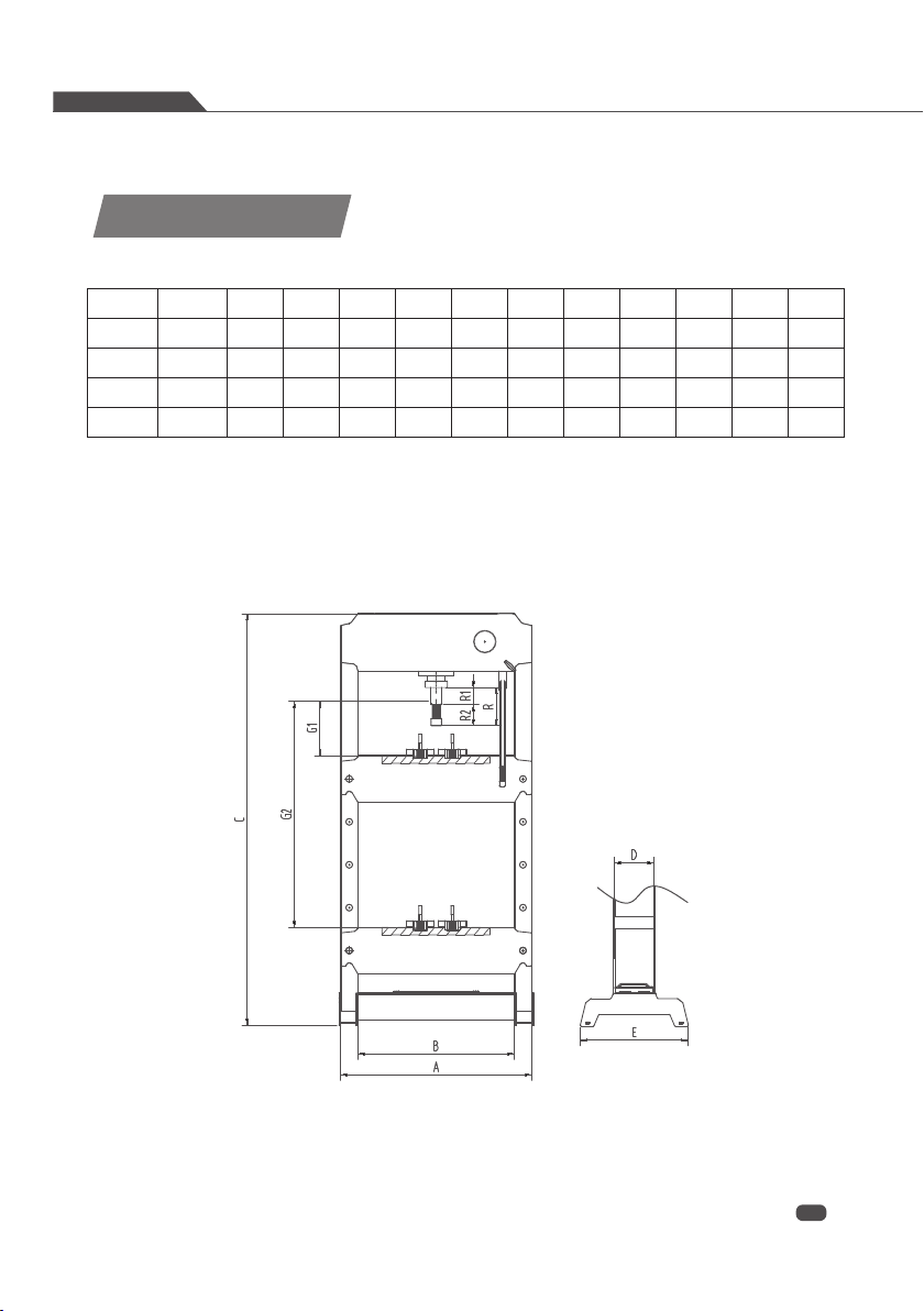
Item No.
SP-15HL
SP-20H
SP-20HAM
SP-30H
SP-30HM
SP-30HAM
SP-50HM
SP-50HAM
A
565
710
770
710
770
770
930
930
B
440
540
600
540
600
600
750
750
C
855
1800
1800
1800
1800
1800
1900
1900
D
134
134
152
134
148
148
200
200
E
355
505
505
505
505
505
535
535
G1
45
25
25
25
25
25
80
80
G2
340
850
850
850
850
850
780
780
R
170
220
220
220
220
220
220
220
R1
95
145
145
145
145
145
145
145
R2
75
75
75
75
75
75
75
75
M
200
/
200
200
280
280
/
Safety Instructions
WORKSHOP PRESSES
01
02
Technical Data
Capacity
15 Ton
20 Ton
20 Ton
30 Ton
30 Ton
30 Ton
50 Ton
50 Ton