2
Owner’s Manual Index
Safety and Warnings ...........................................................................................2-6
Bike ID and Sizing......................................................................................................7
Parts and Assembly..............................................................................................8-17
Operating your e-Bike..................................................................................... 18-19
Shift System.................................................................................................................. 20-23
Maintenance and Service ............................................................................ 24-29
• General Info, Battery Storage, Replacement and Disposal
Troubleshooting ........................................................................................................30
Warranty .............................................................................................................................31
Contact Information...................................................................Back Cover
IMPORTANT! Before using the unit for the rst time fullly charge the
Battery. Battery Charger will shut o when Battery is fully charged, but
never charge longer than 12 hours.
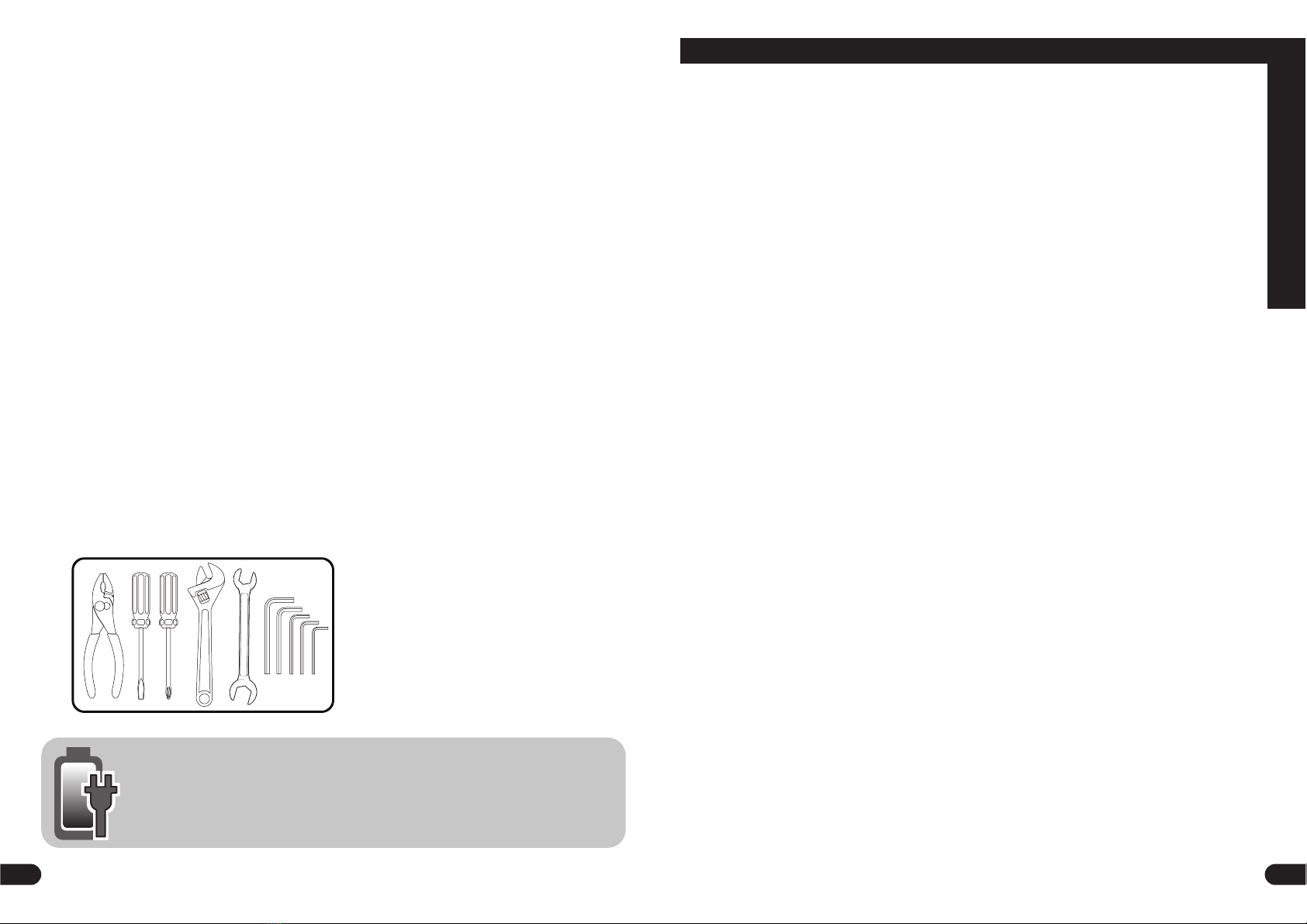
Tools Recommended:
Gather these tools for quick
assembly.
(Metric Wrenches)
31
Limited Warranty - US
General:
Part or model specications are subject to change
without notice.
This Limited Warranty is the only warranty for the
product. ALL WARRANTIES OTHER THAN STATED
HEREIN ARE DISCLAIMED INCLUDING IMPLIED
WARRANTIES OF MERCHANTABILITY AND
FITNESS FOR A PARTICULAR PURPOSE, TO THE
EXTENT ALLOWABLE BY APPLICABLE LAW. ALL
LIABILITY FOR INCIDENTAL, PUNITIVE, SPECIAL,
OR CONSEQUENTIAL DAMAGES ARE EXPRESSLY
DISCLAIMED, TO THE EXTENT ALLOWABLE BY
APPLICABLE LAW.
The only uses for this product are described in this
manual.
Warranty registration is not required.
The Limited Warranty extends only to the original
consumer and is not transferable to anyone else.
What does this Limited Warranty cover?
This Limited Warranty covers defects in
workmanship and materials for all parts of the
product except those indicated below as not
warranted.
What must you do to keep the Limited
Warranty in eect?
This Limited Warranty is eective only if:
• Product is completely and correctly assembled.
• Product is used under normal conditions for its
intended purpose (see the following section for
excluded activities).
• Product receives all necessary maintenance and
adjustments.
• Product is used for general transportation and
recreational use only.
What is not covered by this Limited
Warranty?
This product is designed for recreational use only.
This Limited Warranty does not cover normal
wear and tear, normal maintenance items, or any
damage, failure, or loss that is caused by improper
assembly, maintenance, adjustment, storage, or
use of the product. This Limited Warranty does not
extend to future performance.
This Limited Warranty will be void if the
product is ever:
• Used in any competitive sport
• Used for stunt riding, jumping, aerobatics or
similar activity
• Modied in any way
• Modied with the addition of a motor
• Ridden by more than one person at a time
• Rented, sold, or given away
• Used in a manner contrary to the instructions
and warnings in this Owner’s Manual
What will The Manufacturer do?
Manufacturer’s sole and exclusive obligation
under this Limited Warranty is to repair and/or
replace, at its sole option, any covered defect in
workmanship or materials.
How do you get service?
Contact the Customer Service Department.
• See included list for Customer Contact informa-
tion.
What rights do you have?
This Limited Warranty gives you specic legal
rights. You may also have other rights which vary
from State to State.
For how long does this Limited Warranty
last?
• When used in this Limited Warranty, the phrase
“for life” means for as long as the original con-
sumer owns the product.
• Drive Battery - 90 days
• Electronics - 90 days
• All other Components - 6 months
• When used in this Limited Warranty, the phrase
“for life” means for as long as the original
consumer owns the product.
• The frame is warranted for life except aluminum
frames which are warranted for ten (10) years,
from the date of purchase.
• The fork is warranted for life except for shock
forks which are warranted one (1) year from date
of purchase.
• Drive Battery - 2 years
• Electronics - 2 years
• All other Components - 6 months
Warranty