BVA PA1500M User manual

Printed in Taiwan
MODEL: PA1500M
Air Hydraulic Pump
Instruction Manual
SFA Companies 10939 N. Pomona Ave. Kansas City, MO 64153
Tel: 888-332-6419 * Fax: 816-891-6599
E-mail: [email protected] Website: www.bvahydraulics.com
Maximum Operating Pressure 10,000 PSI
PA1500M-M0 rev 08/07
This is the safety alert symbol. It is used to alert you to potential personal injury hazards.
Obey all safety messages that follow this symbol to avoid possible injury or death.
!

2
Figure 1 - Model PA1500M Components
Control Valve Knob
Manifold Plug/
Oil Output Port
Oil Reservoir
SPECIFICATIONS
Carry Handle
Plastic Cap/ Air Input Port
Model
Number
Usable Oil
Capacity
(in3)
Rated
Pressure
(psi)
Output Flow Rate
(in3/min)
Input Air
Pressure
(psi)
Output
Port
Threads
Input
Port
Threads
Weight
(lbs)
No Load Load
PA1500M 91.5 10,000 66 11 110-175 3/8"-18NPT 1/4"-18NPT 19.4
Foot Pedal
Save these instructions. For your safety, read and
understand the information contained within. The owner and
operator shall have an understanding of this product and safe
operating procedures before attempting to use this product.
Instructions and safety information shall be conveyed in
the operator's native language before use of this product
is authorized. Make certain that the operator thoroughly
understands the inherent dangers associated with the use and
misuse of the product. If any doubt exists as to the safe and
proper use of this product as outlined in this factory authorized
manual, remove from service immediately.
Inspect before each use. It is recommended that, prior to
each use, an inspection be done by qualified personnel and
that any missing or damaged parts, decals, warning/ safety
labels or signs be replaced with BVA Hydraulics authorized
replacement parts only. Any pump that appears to be damaged
in any way, is worn, leaking or operates abnormally shall be
removed from service immediately until such time as repairs
can be made. Any pump that has been or suspected to have
been subject to a shock load (a load dropped suddenly,
causing the system pressure to exceed 10,000 PSI), shall
be removed from service immediately until checked out by
a BVA Hydraulics authorized service center. Owners and
operators of this equipment shall be aware that the use and
subsequent repair of this equipment may require special
training and knowledge.
!
!
PRODUCT DESCRIPTION
BVA Hydraulics Double Acting Air Hydraulic Pump is
engineered to meet most industrial standards for Performance
and Safety. It is an air hydraulic pump with 4-way valve.
It’s unique hydraulic circuit allows quick displacement of
hydraulic fluid under no load conditions and easy pumping
in loaded conditions. Pump supplies compressed hydraulic
fluid to compatible double-acting cylinder, anywhere that
10,000 PSI of fluid pressure is needed. It is suited for plant
maintenance, production, bolting, vehicle repair, and any task
that requires hydraulic pressure from air input. Special skill,
knowledge and training may be required for a specific task
and the product may not be suitable for all the jobs described
above. Unsuitable applications would include applications
that call for a device to move, level or support persons,
animals, hazardous materials, mobile homes/ dwellings in
general, mirrors and/or plate glass, and/or to connect/secure
hatches, components, etc. between bulkheads. The user
must ultimately make the decision regarding suitability of the
product for any given task and assume the responsibility of
safety for himself and others in the work area.
WARNING:
To reduce the risk of personal injury and/or
property damage, ensure that the rated working pressure of
each pressurized attachment be equal to or greater than the
rated working pressure developed by the hydraulic pump.
Always check connections before using. Alteration
of these products is strictly prohibited. Use only those
adapters and attachments provided and approved by the
manufacturer.

3
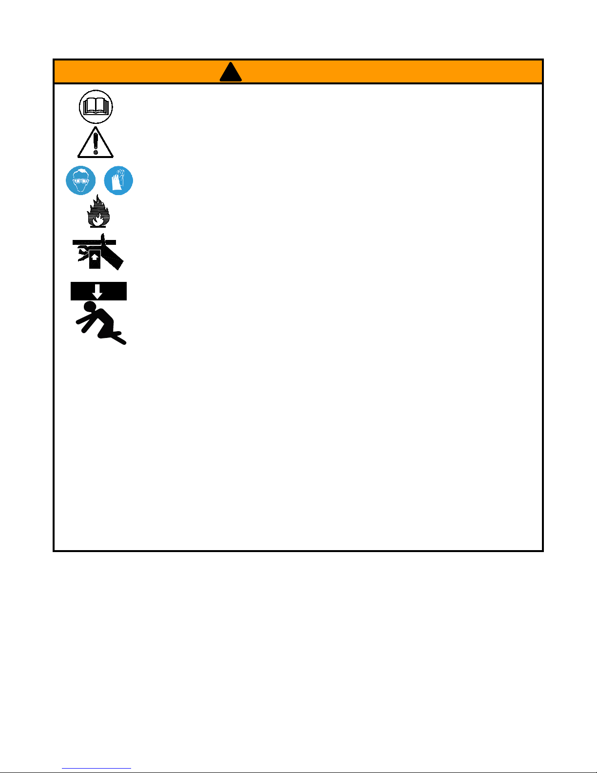
• Study, understand, and follow all
instructions provided with and on this
device before use.
• All WARNING statements must be
carefully observed to help prevent
personal injury.
•
No alteration shall be made to this
device.
• Always wear protective gear when
operating hydraulic equipment.
• Keep hydraulic equipment away from
flames and heat. Hydraulic fluid can
ignite and burn. Do not operate if
leaks are detected.
•
Crush Hazard. Keep hands and feet
away from loading area. Avoid pinch
points or crush points that can be
created by the load, cylinder, or any
equipment of system.
•
To avoid crushing and related injuries:
NEVER work on, under or around
a lifted load before it is properly
supported by appropriate mechanical
means. Never rely on hydraulic
pressure alone to support load.
! WARNING
HYDRAULIC PUMPS
•
The user must be a qualified operator familiar with the
correct operation, maintenance, and use of pumps. Lack of
knowledge in any of these areas can lead to personal injury.
• Do not exceed rated capacity of the pump or any equipment
in the system.
• Never attempt to lift a load weighing more than the capacity
of the cylinder.
• Burst hazard exists if hose or connection pressure exceeds
rated pressure.
• Do not subject the pump and its components to shock
loads.
•
Inspect pump, cylinder, hoses and connections before each
use to prevent unsafe conditions from developing. Do not
use if they are damaged, altered or in poor condition. Do
not operate the system with bent or damaged coupler or
damaged threads.
• Never hold or stand directly in line with any hydraulic
connections while pressurizing.
•
Use gauge or other load measuring instrument to verify load.
• Never attempt to disconnect hydraulic connections under
pressure. Release all line pressure before disconnecting
hoses.
•
Use only approved accessories and approved hydraulic fluid.
•
Never attach ANY component not authorized by manufacturer.
• Always ensure that the chosen application is stable to work
on and around.
• Do not connect to application which can return more oil to
the reservoir than the pump reservoir can hold.
• Do not connect pump to hydraulic system powered by
another pump.
• This device is not suitable for use as support device! As
the system load is lifted, use blocking and cribbing to guard
against a falling load.
• All personnel must be clear before lowering load or
depressurizing the system.
• Never try to disassemble a hydraulic cylinder, refer repairs
to qualified, authorized personnel.
HYDRAULIC HOSES & FLUID TRANSMISSION LINES
• Avoid short runs of straight line tubing. Straight line runs
do not provide for expansion and contraction due to
pressure and/or temperature changes.
• Reduce stress in tube lines. Long tubing runs should be
supported by brackets or clips. Before operating the pump,
tighten all hose connections with proper tools. Do not
overtighten. Connections should only be tightened securely
and leak-free. Overtightening can cause premature thread
failure or high pressure fittings to burst.
• Should a hydraulic hose ever rupture, burst or need to be
disconnected, immediately shut off the pump and release
all pressure. Never attempt to grasp a leaking pressurized
hose with your hands. The force of escaping hydraulic fluid
can inflict injury.
• Do not subject the hose to potential hazard such as fire,
sharp objects, extreme heat or cold, or heavy impact.
• Do not allow the hose to kink, twist, curl, crush, cut or bend
so tightly that the fluid flow within the hose is blocked or
reduced. Periodically inspect the hose for wear.
• Do not pull, position or move setup by the hose.
• Hose material and coupler seals must be compatible with
hydraulic fluid used. Hoses also must not come in contact
with corrosive materials such as battery acid, creosote-
impregnated objects and wet paint. Never paint a coupler
or hose.
•
FAILURE TO HEED THESE WARNINGS MAY RESULT IN
PERSONAL INJURY AS WELL AS PROPERTY DAMAGE.

4
Port A Port B Port A Port B
Port A Port B
Position 1: Pressurized oil
flows to port “B”, port “A”
returns flow to tank.
P T P T P T
Position 2: Neutral, portss
“A” and "B" are closed. Hold
Position.
Position 1: Pressurized oil
flows to port “A”, port “B”
returns flow to tank.
1
2
3
Port A Port B
Figure 2 - Flowpath of the valve positions and operations
OPERATION
To reduce the risk of personal injury and/or
property
damage, Hydraulic connections must be securely fastened
before building pressure in the system. Release all system
pressure before loosening any hydraulic connection in the
system.
Always monitor pressure, load or position using
suitable equipment. Pressure may be monitored by means of
an optional manifold and gauge. Load may be monitored by
means of a load cell and digital indicator. Correct application
position can only be determined by the operator of the
equipment.
1. Connect air supply to the 1/4” NPT air nipple.
2. Remove manifold plug, connect to hydraulic hoses and
suitable application.
3. Shift the valve to desired position. There are three positions
available, refer to Figure 2 on below for the flowpath.
4. After shifting the valve, press on the foot pedal until desired
pressure, load or position is reached. Always monitor
pressure, load or position using suitable equipment.
Pressure may be monitored by means of optional
manifolds and gauges (contact BVA Hydraulics). Load
may be monitored by means of a load cells and digital
indicators.
Note. Do not continue to operate pump after cylinder plunger
is fully extended or retracted.
5. Release the foot pedal will stop the pump flow.
Note: Both air input ports use a 1/4 NPT air nipple (not
included). It is recommended to install an inline air filter
upstream from the pump to provide clean, lubricated air.
Contact BVA Hydraulics for necessary accessories.
!
!
BEFORE USE
1.
Before using this product, read the instruction manual
completely and familiarize yourself thoroughly with the
product and the hazards associated with its improper use.
2. Know your pump, its limitations and how it operates before
attempting to use.
3. Replace shipping plug (red color) with air vent plug (black
color) before use. Refer to item #68 on Service Parts
Sheet.
4. Remove plastic cap from the air inlet port on the end of the
pump, then connect with a 1/4”NPT air nipple (not supply
with pump). Use teflon tape or similar thread sealant on
thread connection.
Note: When using the teflon tape or pipe thread compound.
Tighten securely to prevent accidental removal of compound
while in use. Take care not to introduce compound into port
orifices.

TROUBLESHOOTING GUIDE
The following information is intended as an aid in determining if problem exists. Pumps should be repaired only by authorized
BVA Service Center. For repair service, contact service center in your area.
Symptom Possible Causes Corrective Action
Application does not extend, move or
respond to pressurized fluid
• Overload condition
• Loose couplers
• Faulty couplers
• Pump malfunction
• Inadequate air supply
• Remedy overload condition
• Tighten couplers
• Replace couplers
• Contact service center
• Ensure air source can dedicate
7.8 CFM @ 110~175 PSI
Application responds to pressurized
fluid, but system does not maintain
pressure
• Overload condition
• Pump or valve malfunction
• Application/connection leaking
• Remedy overload condition
• Contact Service Center
• Replace application/connection
Application responds slower than
normal
• Loose connection or coupler
• Restricted hydraulic line or fitting
• Application/connection leaking
• Tighten connection or coupler
• Clean and replace if damaged
• Replace application/connection
Application does not return fluid to
pump (i.e. cylinder will not retract)
• Malfunctioning coupler, damaged ap-
plication
• Secure load by other means.
Depressurize pump and hose,
remove coupler and/or application,
then renew or replace
Application does not fully extend (cyl-
inder or spreader)
• Reservoir overfilled
• Fluid level in pump is low
• Secure load by other means.
Depressurize pump and hose,
remove application, then drain fluid to
proper level
• Secure load by other means.
Depressurize pump and hose,
remove application, then fill fluid to
proper level
Poor performance • Fluid level in pump is low • Ensure proper fluid level
5
MAINTENANCE
Important: Use only a good quality hydraulic jack fluid. Never
use brake fluid, transmission fluid, turbine oil, motor oil, alcohol,
glycerin etc. Use of other than good quality hydraulic oil will
void warranty and damage the pump, hose, and application.
We recommend Mobil DTE 13M or equivalent.
1. Inspect hoses and connections daily. Replace damaged
components immediately with BVA Hydraulics replacement
parts only.
2. Tighten connections as needed. Use non-hardening pipe
thread compound when servicing connections.
3. Use only good quality hydraulic fluid. We recommend Mobil
DTE 13M or equivalent.
Adding Hydraulic Fluid
1. Depressurize and disconnect hydraulic hoses from
application.
2. With pump in upright, horizontal position, remove the air
vent plug located on the top plate of the reservoir.
3. Use a small funnel to fill reservoir to within 3/4" (19mm) of
the opening.
4. Wipe up any spilled fluid and reinstall the air vent plug.
Changing Hydraulic Fluid
1. For best results, change fluid once a year.
2. Repeat step 2 on Adding Hydraulic Fluid, then pour used
fluid into a sealable container.
3. Dispose of fluid in accordance with local regulations.
4. Fill with a good quality hydraulic jack oil as recommended
above. Reinstall air vent plug.
Lubrication
When pump is operated on daily basis, the manufacturer
recommends installing an inline oiler and air dryer. Use SAE
grade oil (5W to 30W).
Storage
1. When not in use, depressurize and disconnect hydraulic
hoses from application.
2. Wipe clean, thoroughly.
3. Store in clean, dry environment. Avoid temperature
extremes.
4. For transportation or long storage, replace the air vent plug
with shipping plug.
5. Shield pump with a protective cover.

6
PA1500M-M0
rev 08/07
Parts Illustration
Note: Not all components of the pump are replacement items, but are illustrated as a
convenient reference of location and position in the assembly sequence.
Note: To ensure safe and reliable performance, replace worn or damaged parts with BVA Hydraulics
Authorized Replacement Parts only.
MODEL: PA1500M
Air Hydraulic Pump
Service Parts
SFA Companies 10939 N. Pomona Ave. Kansas City, MO 64153
Tel: 888-332-6419 * Fax: 816-891-6599
E-mail: [email protected] Website: www.bvahydraulics.com

7
Parts List
PA1500M-M0
rev 08/07
Note: Not all components of the pump are replacement items, but are illustrated as a
convenient reference of location and position in the assembly sequence.
MODEL: PA1500M
Air Hydraulic Pump
Service Parts
SFA Companies 10939 N. Pomona Ave. Kansas City, MO 64153
Tel: 888-332-6419 * Fax: 816-891-6599
E-mail: [email protected] Website: www.bvahydraulics.com
Item Part Number Description Qty
1 649-1-0050-055 Allen Screw 9
2 A67-6-1005-109 Control valve cover 1
3 644-1-0060-071 Set screw 1
4 649-1-0080-003 Allen screw 4
5 A67-6-1009-107 Control valve base 1
6 A67-6-1006-101 Bearing washer 2
7 623-6-2542-104 Bearing 1
8 * O-ring 2
9 A67-6-1003-105 Control valve 1
10 * O-ring 1
11 A67-6-1001-101 Oil outlet valve 3
12 606-3-0008-101 Spring washer 3
13 * Back-up ring 3
14 * O-ring 3
15 D05-6-1001-106 Manifold plug (oil
output port)
2
16 641-1-0098-103 Screw 2
17 A67-6-1011-104 Carry handle 1
18 * Gasket 1
19 * O-ring 2
20 * Back-up ring 2
21 A57-6-4002-201 Oil outlet valve 1
22 512-2-0043-108 Compression spring 1
23 601-7-0009-001 Steel ball 1
24 * O-ring 1
25 * Washer 6
26 A67-6-1015-102 Top reservoir plate 1
27 A67-6-1601-105 Base 1
28 * Crush washer 2
29 A59-6-1017-102 Relief valve cylinder 1
30 A17-6-1216-102 Relief valve stem 1
31 * Compression spring 1
32 A17-5-1603-300 Relief valve screw 1
33 601-7-0008-009 Steel ball 1
34 A59-6-1015-108 Oil entrance valve 1
35 520-8-0134-101 Filter 1
36 * Gasket 1
37 A57-6-1601-107 Oil reservoir 1
38 649-1-0060-122 Allen screw 4
Item Part Number Description Qty
39 A57-6-1002-105 End plate, air motor 1
40 A17-6-2105-108 Washer 2
41 A17-4-2100-500 Air motor piston 1
42 A57-6-1003-107 Cylinder, air motor 1
43 A57-3-1011-108 Pump piston 1
44 512-2-0410-017 Compression spring 1
45 A57-6-1014-102 Pump piston guide 1
46 A57-6-2023-108 Bushing 1
47 * Back-up ring 1
48 * U-cup 1
49 A59-6-1013-105 Pump piston cylinder 1
50 A57-6-1016-106 Spacer 1
51 * Crush washer 1
52 * Gasket 1
53 * O-ring 3
54 512-2-0092-101 Compression spring 1
55 649-1-0040-007 Screw 1
56 A57-6-5004-109 Air entrance cover 1
57 * O-ring 1
58 A17-6-1105-103 Plastic cap (air inlet
port)
1
59 649-1-0050-046 Screw 2
60 A57-6-5001-103 Air entrance base 1
61 A57-6-5003-107 Air entrance valve 1
62 * O-ring 1
63 666-5-0250-108 C-clip 1
64 A17-6-1002-103 Noise suppressor 1
65 A67-6-1007-103 Foot pedal 1
66 A67-6-1014-100 Oil manifold 1
67 649-1-0050-101 Screw 4
68a A57-3-5007-107 Shipping Plug (red) 1
68b A57-33-1900-109 Air vent plug (black) 1
69 601-4-0030-095 Spring pin 1
70 512-2-0046-104 Compression spring 2
71 601-7-0006-005 Steel ball 2
72 A67-6-1012-106 Control valve lever 1
73 E05-6-1008-109 Control valve knob 1
(*) A67-3-9901-109 Seal kit -
(*) indicates items included in, and available only as part
of Seal Kit

LIMITED LIFETIME WARRANTY
BVA Hydraulics®, represented in the United States by SFA Companies [“SFA”] warrants this product to be free from defects in
material and workmanship for the life of the product as long as the original purchaser owns the product. The warranty is non-
transferable and is subject to the terms, exclusions, and limitations described below:
• Damaged components, including but not limited to bent rams, dented or crushed cylinder walls, broken welds or couplers as
well as worn out seals, o-rings and springs are the result of misuse and not covered by warranty and BVA Hydraulics will not
provide any warranty credit for such damaged components.
• This warranty does not cover ordinary wear and tear, overloading, alterations (including repairs or attempted repairs not
performed by BVA Hydraulics or one of its authorized personnel), improper fluid use, or use of the product in any manner for
which the product was not intended or the use of which is not in accordance with the instructions or warnings provided with
the product.
• In the unlikely event that a BVA Hydraulics product fails due to material defect in workmanship, you may contact SFA for
disposition. In such cases, the customer’s sole and exclusive remedy for any breach or alleged breach of warranty is limited
to the repair or replacement of the defective product.
• Under no circumstances is BVA Hydraulics liable for any consequential or incidental damage or loss whatsoever.
• THIS WARRANTY IS LIMITED TO NEW PRODUCTS SOLD THROUGH AUTHORIZED DISTRIBUTORS AND OTHER
CHANNELS DESIGNATED BY BVA HYDRAULICS. NO AGENT, EMPLOYEE OR OTHER REPRESENTATIVE OF BVA
HYDRAULICS IS AUTHORIZED TO MODIFY THIS WARRANTY.
• THE FOREGOING IS EXCLUSIVE AND IS IN LIEU OF ALL OTHER EXPRESS AND IMPLIED WARRANTIES, INCLUDING
BUT NOT LIMITED TO THE IMPLIED WARRANTIES OF MERCHANTABILITY AND FOR A FITNESS FOR A PARTICULAR
PURPOSE.
• Components not manufactured by BVA Hydraulics including certain motor systems, gasoline engines, and others are not
covered by this warranty and instead are covered by the manufacturer’s separate manufacturer’s warranty provided in the
package.
• BVA Hydraulics’ liability in all cases is limited to, and will not exceed the purchase price paid for the product.
SFA Companies
10939 N. Pomona Ave. Kansas City, MO 64153
Tel: 888-332-6419
E-mail: [email protected]
8
Table of contents
Other BVA Water Pump manuals
Popular Water Pump manuals by other brands

Craftsman
Craftsman 390.269151 owner's manual

ITT
ITT E1-BCANCT1W-06 Installation & operating manual

Victor Pumps
Victor Pumps C Series Instruction and maintenance manual

bluelab
bluelab PeriPod M4 manual

Agilent Technologies
Agilent Technologies TPS-mini 9699180 user manual

BUSCH
BUSCH R 5 series instruction manual