BVF SRHC 18-36 User manual

BVF SRHC 18-36
Self Regulating Heating Cable
BVFHEATING.COM
1. General Information
1.1 Use of the Manual
This manual describes the BVF SRHC 18-36 heating cable — how to design and install the system, connect to cold lead and equip the cable with
connecting set. It is important to thoroughly review this manual before installation. For additional information contact to the distributor.
1.2 Safety Guidelines
The safety and reliability of any electric heat tracing system depends on proper design, installation, and testing. Incorrect installation or
mishandling of the product can cause damage to the heating cable, system components and property, and can create a risk of re or shock. The
guidelines and instructions contained in this guide are important. Follow them carefully to minimize these risks and to ensure that the BVF SRHC
18-36 heating cable performs reliably.
IIMPORTANT SAFETY NOTICE WARNING: Shock and re hazard!
• If the BVF SRHC 18-36 heating cable is damaged or not installed properly, re or shock hazard could occur resulting in serious personal
injuries or damage to property. You must follow carefully the warnings and instructions contained in this manual.
• Use controllers designed only for electric heat tracing systems.
• It is important that this equipment is installed only by qualied electricians who are familiar with the proper sizing, installation, construction
and operation of electric heat tracing systems and the hazards involved. Installation must comply with all national and local electrical
regulations. If you are unfamiliar with these requirements, please contact an electrician.
• The BVF SRHC 18-36 heating cable is designed for defrosting purposes only. Be sure that the installation surfaces are well prepared for
installation.
• If the BVF SRHC 18-36 heating cable is damaged, it must be replaced. Do not attempt to splice or repair any part of the system.
1.3 Measure resistance
iMeasure the resistance during the installation
Remember to always measure, verify and record the actual resistance throughout the installation process.
1.4 10 years Extended Warranty
For a period of ten (10) years from the date of purchase warrants that the BVF SRHC 18-36 heating cable is free from defects in material,
design and workmanship. The extended warranty is only valid if the warranty certicate has been properly completed, and the installation is in
accordance with the installation instructions.
1.5 Distributor’s Statement
The distributor can accept no responsibility for possible errors in catalogues, brochures, other printed materials, and website information. The
distributor reserves the right to alter its products without notice. ‘BVF Heating Solutions’ is a registered trademark of BVF Heating Solutions Ltd.
All rights reserved.
2. BVF SRHC specication
2.2 Structure of the BVF SRHC 18-36 heating cable2.1 The specic heating performance according to the ambient
temperature
INSTALLATION AND USER MANUAL
Outer jacket Braid
Inner jacket Conductive core
Bus wires

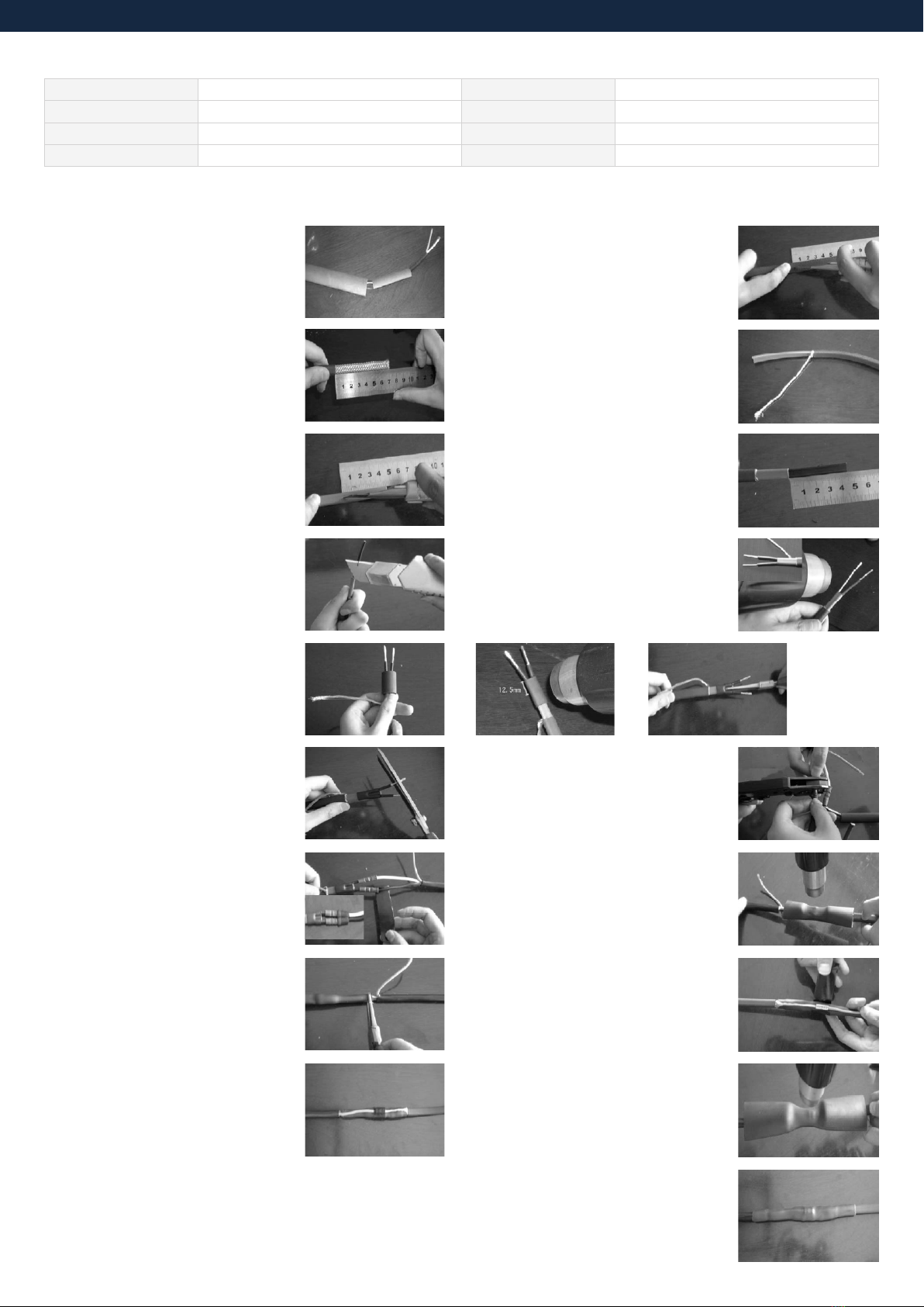
3. Installation of the cold lead to the heating cable with the connection set
3.1 Slide 127mm tube and 203mm black
heat shrinkable tube over end of the plug-
in cord.
3.5 Lightly score completely around and
then pull down inner jacket. The length is
45mm.
3.3 Bend heating cable to break jacket at
score then peel o outer jacket.
3.7 Skive matrix material from conductors
with utility knife.
3.10 Trim the front bus wires to 7mm.
3.12 Remove release paper from strips,
wrap one strip of mastic around the black
wire against the end of the splice.
To provide a water block, then repeat
for the white wire squeeze the mastic
together.
3.14 Make sure the adhesive will appear
at both ends. Immediately after shrinking,
pinch rst one end of the tube and then
the other end.
3.16 Wrap black cloth tape evenly around
crimp and splice. Cover crimp completely.
3.18 Plug the grey cap onto the opposite end of the cable. Never
shortcut the cable ends. The jelly will ensure the insulation of the
connection.
3.9 Center the 15mm × 25mm
heatshrinkable tube over the end of
heating cable as
shown. Immediately after shrinking, pinch
with pliers between wires while tube is still
hot. Hold for 10 seconds to ensure seal.
3.2 Lightly score completely around and
then down outer jacket. The length is
70mm.
3.6 Bend heating cable to break jacket at
score, then peel o inner jacket.
3.4 Unravel the braid back to the out
jacket. Straighten the braid and twist into a
“pigtail”.
3.8 Slide the 3.2mm × 25mm shrink tubes
over bus wires. To shrink tubing move
heat source continuously from side to
side. While shrinking, ensure that tubes
remain up against black.
3.11 Use insulated bus wire crimps or
a crimp tool to connect black and white
wires to bus wires of heating cable.
Polarity does not matter.
3.13 Center the 127mm heat shrinkable
tube over the splice. Shrink the tube
completely.
3.15 Use crimp tool to connect braid to
ground wire.
3.17 Center the 203mm heatshrinkable
tube over and shrink the tube completely.
Make sure the ring of adhesive will appear
at both ends. Total heating time should be
about 3 minutes.
Cable Construction: Twin conductor self regulating heating cable Conductor Insulation: THP
Rated Voltage: 230V Outer Insulation: THP
Output: 18-36W/m ±10% Max. Ambient Temp.: + 65 °C
Cable Diameter: 10,5 x 5,9mm Max. cable length: ~75m @16A 0°C
2.3 BVF SRHC technical data
Other manuals for SRHC 18-36
1