Thermon Fastrax User manual
Part No. HF17256.Rev.1 Issued December 2021 Printed in Canada
IMPORTANT INSTRUCTIONS - SAVE THESE INSTRUCTIONS
Read all instructions before installing or using the heater. Please adhere to instructions published in this manual.
Failure to do so may be dangerous and may void certain provisions of your warranty.
Fastrax®is a registered trademark of Thermon.
Copyright©2021. All rights reserved.
ISO 9001
Energy Management
System (EMS)
Installation & Operation Manual
Rail Thermostat
Control Box
ArcticSense
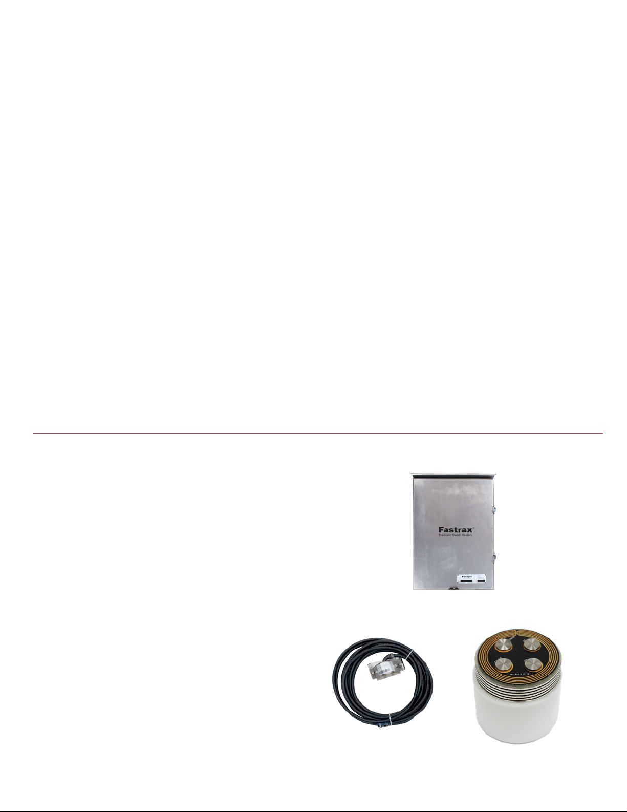
TABLE OF CONTENTS
A. Energy Management System Overview 2
A.1 Overview ............................................................................... 2
B. EMS Installation 3
B.1 Mounting EMS Control Box ..................................... 3
B.2 Mounting Precipitation Sensor............................ 3
B.3 Mounting Rail Thermostat...................................... 3
C. Electrical Connections Overview 5
C.1 Power ..................................................................................... 5
C.2 Control .................................................................................. 5
C.3 Alarm Indication ............................................................ 5
C.4 Aggressive Retry ........................................................... 5
C.5 Operation and Adjustments.................................. 5
C.6 Switches & Dials..............................................................6
C.7 Status LEDs ........................................................................6
D. Spare Parts & Drawings 7
D.1 Schematic - EMS Board Single Unit ..................8
A. ENERGY MANAGEMENT SYSTEM OVERVIEW
A.1 Overview
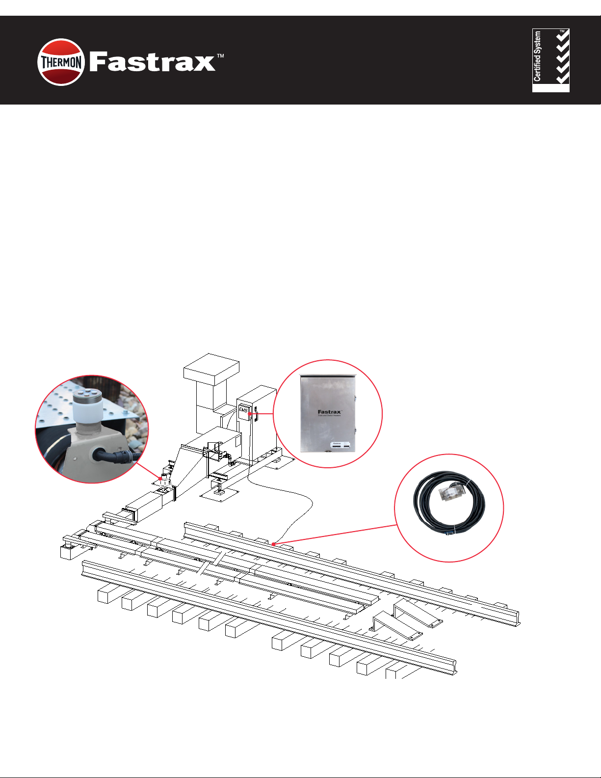
1. The Energy Management System (EMS) allows
automatic control of a railway switch heater. It detects
moisture and senses ambient, and rail temperature,
turning the heater on when it snows and the rail is
cold.
2. The EMS provides an aggressive retry for heaters
equipped with the appropriate remote Flame Safety
Relay reset.
3. The EMS provides a low temperature cut out feature
for use with propane red heaters that do not have
tank heaters and are located in cold environments
where the temperature drops below -30°C (-22°F) to
avoid nuisance shutdowns due to insufcient vapour
pressure.
4. There are two EMS versions, 17255-01 comes with a
precipitation sensor, ambient temperature sensor,
rail thermostat, and control box, as shown. Whereas
version 17255-02, does not include the rail thermostat.
Control Box
Rail Thermostat
ArcticSense
Precipitation Sensor

3
B. EMS INSTALLATION
B.1 Mounting EMS Control Box
1. Mount the EMS control box in a convenient location
on, or next to, the heater.
B.2 Mounting Precipitation Sensor
1. Mount the ArcticSense precipitation sensor on the
sensor duct ange, where it will be exposed to snow
and be in the heated zone. Slotted mounting holes
facilitate attachment to the ange bolts in any of 2
position. Select the position that is most likely to be
exposed to drifting snow.
B.3 Mounting Rail Thermostat
1. Mount the rail thermostat on the eld or gage side
of the stock rail ahead of the points and tie duct,
as shown. Select a location shaded from the sun.
Provide strain relief in the cable, by leaving adequate
slack, as shown, to allow for rail pumping.
Remove the yellow shim washers when installed on
115 lb rail or lighter. Loosen the two mounting bolts
and attach the rail thermostat to the rail ange by
tapping it on with a hammer. Once in place tighten
mounting bolts to maximize grip.
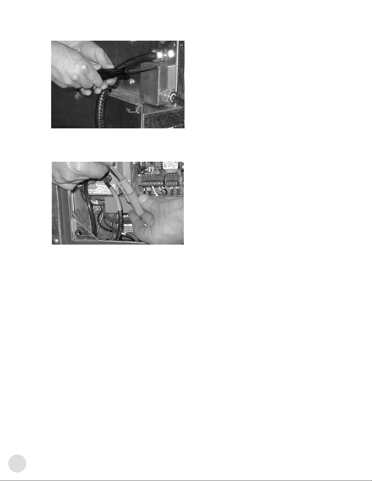
2. Remove the four (4) Phillips screws, the cover, and
the plug from the hole in the rail temperature surge
protection box.
3. Pass the two (2) wires from the rail temperature
sensor through the hole, install the locknut and
tighten.
4. Insert, one each of the bared wires into the two
terminalks on the surge suppression circuit board,
and tighten. There is no polarity.
4
5. Replace the cover, tighten the four (4) Phillips screws.
6. Connect the surge isolator two pin connector with the
mating plug located inside the electrical component
area, hanging immediately under the DSI.
55
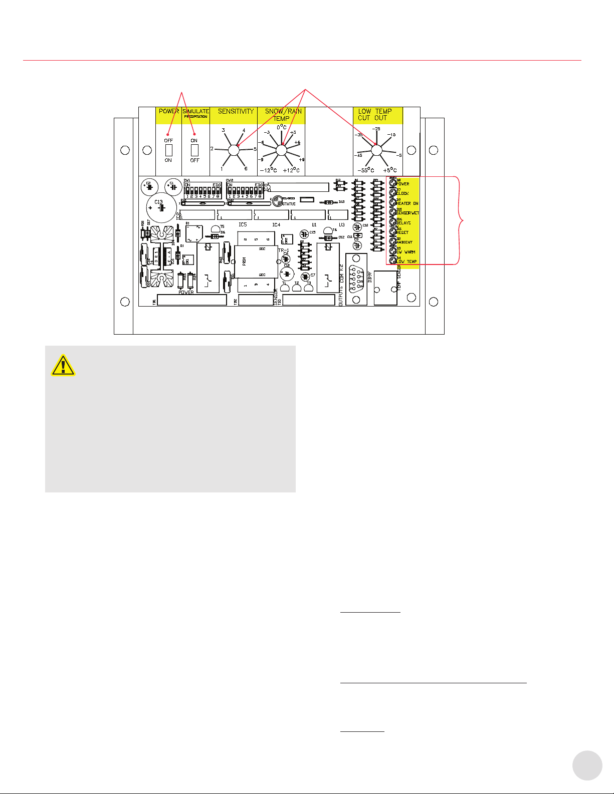
C. ELECTRICAL CONNECTIONS OVERVIEW
Status LEDs
Power & Simulate
Precipitation Switches Set Point Dials
CAUTION
CAUTION. Disconnect heater from power supply at
integral disconnect or fuse box before opening
closures or servicing heater.
Lock the switch in the “OFF” (open) position and
tag the switch to prevent unexpected power
application.
This heater should only be serviced by qualied
personnel with electrical heating equipment
experience.
Install and use the heater in accordance with local
codes and this Owner’s Manual.
NOTE: Refer to schematic inside door for electrical connections.
C.1 Power
Connect 120V power to terminals 1 and 3, and ground
wire to ground stud.
C.2 Control
Connect heater control to terminals 9 and 8, (Normally
Open, NO) or 9 and 7 (Normally Closed, NC).
C.3 Alarm Indication
1. A 120Vac Alarm signal from the heater can be used to
trigger the aggressive retry feature of the EMS.
1.1 Connect the Alarm Neutral terminal 6 to the
neutral in the heater. Connect the Alarm signal
(120Vac) from the heater to terminal 5 on EMS.
1.2 On a MARK VI heater the alarm signal is
available directly on the “ALARM” relay coil,
contact A1.
1.3 On a MARK VII heater connect the alarm signal
to either Terminal Block 1 terminal 1 or to the
“ALARM” relay terminal 2.
1.4 On a Micro heater the signal is available at the
“ALARM” relay terminal 9.
NOTE: YARDMASTER heaters do not require this connection.
The aggressive retry feature is integrated into the
YARDMASTER controller.
C.4 Aggressive Retry
1. If the heater you are controlling is equipped with a
ame safety relay reset module, connect the reset to
the appropriate terminals 14 and 13 (NO). If the heater
is equipped with Direct Spark Igniter connect the
reset normally closed contact, terminals 12 and 14,
into the wire to the request relay.
NOTE: YARDMASTER heaters do not require this connection.
The aggressive retry feature is integrated into the
YARDMASTER controller.
1.1 Turn on power at electrical service. Ensure 5
amp panel breaker is closed.
C.5 Operation and Adjustments
1. Set Point Dials: The EMS board (15919) monitors
environmental conditions based on various set
points. All set points are easily adjustable by dials
located at the top of the EMS board. These set points,
when triggered by environmental conditions, send
out a signal to the controller to turn the heaters on.
2. Power Switch and Moisture Simulation Switch: The
power switch and a moisture simulation switch
enable resetting or disabling the EMS and aid in
troubleshooting.
LED Lights: On the right side of the EMS board there
are a number of LED lights which indicate the status
of the EMS board.

6
6
C.6 Switches & Dials
1. ‘POWER ON/OFF’
This allows you to turn OFF/ON the EMS. This switch
is also used to reset the EMS in case of a lockout. Four
alarms from the heater within less than 5 minutes.
2. ‘SIMULATE PRECIPITATION ON/OFF’
This is normally OFF. To simulate moisture (snow or
rain) you can switch it ON and the EMS receives a
signal the sensor is wet. Used to test and troubleshoot
the EMS.
3. ‘SENSITIVITY’
This knob is used to adjust the sensitivity of the
precipitation sensor. 6 is maximum sensitivity and 1 is
least sensitive. Factory set at 3.5.
4. ‘SNOW-RAIN TEMP’
Adjustable set point, from -12°C to 12°C (10°F to 54°F).
If the ambient temperature is below this set point,
the EMS sees any moisture as snow and will turn the
heater ON. Above this set point it detects rain and
will not turn on the heater.
5. ‘SWITCH WARM TEMP’
This set point is not used with this EMS. This feature is
used only with the intermediate EMS.
6. ‘LOW TEMP CUT OUT’ 5°C to -55°C (41°F to -67°F)
This set point determines the temperature at which the
heater will be turned OFF. Usually set to -35°C (-31°F).
NOTE: Propane gas does not provide adequate vapour pressure
below -40°C/F. By disabling the heater at temperatures
below the set point, alarm shutdown and manual resets
are avoided.
NOTE: Natural gas red heaters or propane tanks with tank
heaters DO NOT require this feature and the set point
can be lowered to the minimum of -55°C (-67°F).
7. ‘DELAY ON’, ‘DELAY OFF’ DIP SWTCHES ON THE
BOARD
These switches are used to set the DELAY ON and
DELAY OFF times for EMS operation. The value of the
time is calculated by adding the binary code value
of the actual switch. Minimum step is one minute.
The values are 1, 2, 4, 8, 16, 32, 64, and 128 and any
combination between, and up to 255 minutes.
Example shown has 5 minutes delay on and 15
minutes delay off.
8. Heaters equipped with the ‘AGGRESSIVE RETRY
OPTION’
If the heater is equipped with the AGGRESSIVE RETRY
OPTION, the EMS will reset the heater up to three
times within 5 minutes and then lock out.
C.7 Status LEDs
Status LED Description
POWER Indicates 12V DC present on the
board
CLOCK Blinking once a second means clock
is working
HEATER ON Heater relay is energized. Heaters
requested to run
SENSOR WET Indicates when the sensor is wet or
simulated wet
DELAYS
Shows Delay Status:
ࢦDark: No delay time active
ࢦLit: Delay time active. Either delay
off or delay on time
–If ‘HEATER ON’ LED is dark -
delay on time
–If ‘HEATER ON’ LED is lit -
delay off time
ࢦBlinking: Delay time reset to zero
RESET Relay to reset ame safety relay.
(Aggressive retry)
AMBIENT Ambient temperature is below
SNOW/RAIN TEMP and sensor is wet
SW WARM
Ambient temperature is below
SWITCH WARM set point (not
available with this EMS)
LOW TEMP
Ambient temperature is below low
temp cut out set point. EMS will turn
the heater off. LED heater on is dark
(heater on relay de-energized)

7
D. SPARE PARTS & DRAWINGS
EMS Board
Part No. 15919
Transformer
Part No. 9064-0016
Circuit Breaker
Part No. 9042-0014
Metal Oxide Varistor
Part No. 9049-0052
Rail thermostat only, 13340-
03 Enclosure only, 17895
Rail thermostat surge
isolator. Replacement board
only, 15948
Rail thermostat jumper
16422-02
Ambient temperature sensor
16426
ArcticSense, c/w 10’ cable
13849-02
ArcticSense head only
13849-03
Rail thermostat c/w 40’ cable
16442-03

8
D.1 Schematic - EMS Board Single Unit
40
41
41
40
15
1
21
9
44
45
46
47
23
25
24
22
ALARM FSR
4 POLE DEUTSCH
CONNECTOR
TEMPERATURE
SENSOR
TRANSFORMER 24V 75VA
MODULE
44
45
46
47
1
2
3
4
FSR RESETHEATER ON
P1
15935
5
1
2
3
5
6
7
8
9
ELECTRICAL SCHEMA
EMS BOARD SINGLE UNIT
COM
NO
NC
HEATER ON CONTACTS
COM
NO
NC
FSR RESET CONTACTS
9
2
21
1
15
22
23
24
25
GND
10
14
13
12
RAIL TEMP.SWITCH
11
S20K130
S20K130
S20K130
S20K130
VARISTOR
VARISTOR
VARISTOR
VARISTOR
TERMINAL BLOCK
TB
IF RAIL TEMP.SWITCH IS NOT USED
SHORT TB 9 TO 11 WITH A JUMPER
RAIL TEMPSWITCH
INSULATION
BOARD
159361
2
RAIL TEMP. SURGE
PROTECTION BOX
1
2
3
4
15947
DEUTSCH
CONNECTOR
16422-03
WITH SURGE PROTECTION ON RAIL TEMP SWITCH
GRu 10.APRIL 2000
PRODUCTION RELEASE REF ECN 949
B
TB1-1
TB1-2
TB1-3
TB1-4
TB1-5
TB1-6
TB1-7
TB2-1
TB2-2
TB2-3
TB2-4
12 AWG GREEN WIRE
12 AWG GREEN WIRE
TB
4
CONNECT POWER GROUND TO GROUND STUD ON ENCLOSURE
13.NOV.2000CGROUNDING INFORMATION ADDED ECN 1125
PRECIPITATION SENSOR
TO GROUND STUD ONENCLOSURE
TO GROUND STUD ONENCLOSURE
DECN 1122 5.DEC.2000
APPLICATION: EMS 17255-XX , LABEL 17254
G
ETB3 TERM NUMBERING CORRECTED, ECN 1200 2. FEB. 2001GCH
EMS BOARD 15919
TB3-5
TB3-4
TB3-6
FECN 1252 TB1 TERMINAL 13 T0 15 RENUMBERED TO 12 TO 14 27.APRIL 2001
GCH
1
2
P2
NEUTRAL
GSNOW SENSOR REPLACED WITH NEW MODEL 5. NOV 2019
REV
DRAWING NUMBER
TITLE
SHEET: 1/1
Thermon Heating Systems, Inc.
DWN: DATE: CHKD DATE: LTRDATE APP
NOTES: EAGLE A4
DESCRIPTION
H1H2
X1X2
AMP
NEUTRAL
9
9
9
20
20
1
1
1
1
TB1
TB2

99
Section Running Footer
NOTES

10
10
NOTES

1111
NOTES

WARRANTY: Under normal use the Company
warrants to the purchaser that defects in material
or workmanship will be repaired or replaced without
charge (from date of shipment) for a period of:
Any claim for warranty must be reported to the sales
of ce where the product was purchased for authorized
repair or replacement within the contract terms.
Subject to State or Provincial law to the contrary, the
Company will not be responsible for any expense for
installation, removal from service, transportation, or
damages of any type whatsoever, including damages
arising from lack of use, business interruptions, or
incidental or consequential damages.
The Company cannot anticipate or control the
conditions of product usage and therefore accepts no
responsibility for the safe application and suitability
of its products when used alone or in combination
with other products. Tests for the safe application and
suitability of the products are the sole responsibility of
the user.
This warranty will be void if, in the judgment of the
Company, the damage, failure or defect is the result of:
�Vibration, radiation, erosion, corrosion, process
contamination, abnormal process conditions,
temperature and pressures, unusual surges or
pulsation, fouling, ordinary wear and tear, lack of
maintenance, incorrectly applied utilities such as
voltage, air, gas, water, and others or any combination
of the aforementioned causes not speci cally allowed
for in the design conditions
�Or, any act or omission by the Purchaser, its agents,
servants or independent contractors which for
greater certainty, but not so as to limit the generality
of the foregoing, includes physical, chemical or
mechanical abuse, accident, improper installation
of the product, improper storage and handling of the
product, improper application or the misalignment
of parts.
No warranty applies to paint nishes except for
manufacturing defects apparent within 30 days from the
date of installation.
The Company neither assumes nor authorizes any person to
assume for it any other obligation or liability in connection
with the product(s).
The Purchaser agrees that all warranty work required after
the initial commissioning of the product will be provided
only if the Company has been paid by the Purchaser in full
accordance with the terms and conditions of the contract.
The Purchaser agrees that the Company makes no
warranty or guarantee, express, implied or statutory,
(including any warranty of merchantability or warranty
of tness for a particular purpose) written or oral, of the
Article or incidental labour, except as is expressed or
contained in the agreement herein.
LIABILITY: Technical data contained in the catalog
or on the website is subject to change without notice.
The Company reserves the right to make dimensional
and other design changes as required. The Purchaser
acknowledges the Company shall not be obligated
to modify those articles manufactured before the
formulation of the changes in design or improvements
of the products by the Company.
The Company shall not be liable to compensate or
indemnify the Purchaser, end user or any other party
against any actions, claims, liabilities, injury, loss,
loss of use, loss of business, damages, indirect or
consequential damages, demands, penalties, nes,
expenses (including legal expenses), costs, obligations
and causes of action of any kind arising wholly or partly
from negligence or omission of the user or the misuse,
incorrect application, unsafe application, incorrect
storage and handling, incorrect installation, lack of
maintenance, improper maintenance or improper
operation of products furnished by the Company.
PLEASE ADHERE TO INSTRUCTIONS IN THIS MANUAL
Failure to do so may be dangerous and may void certain
provisions of your warranty.
�84 months - SwitchBlade®Heaters
�60 months - DC Heaters
�36 months - DC Control Panels
�36 months - HELLFIRE Heaters, FEB Heaters
�12 months - All other Fastrax®Products
For further assistance, please call 1.855.244.3128
Table of contents
Other Thermon Cables And Connectors manuals

Thermon
Thermon Terminator DP-M Reference guide

Thermon
Thermon Terminator DL Reference guide

Thermon
Thermon Terminator DP Reference guide

Thermon
Thermon Terminator ZP/FAK-1 Reference guide

Thermon
Thermon Terminator ZS Reference guide

Thermon
Thermon Terminator DS/DE Reference guide

Thermon
Thermon Terminator DP/FAK-2 Reference guide

Thermon
Thermon Terminator ZP-M Reference guide

Thermon
Thermon Terminator ZP Reference guide

Thermon
Thermon TraceNet ECM-P/FAK-1 Reference guide


