BWT CBE 650 User manual

2019/06 - Indice de révision : A - Code : 33905PROTECTION & SÉCURITÉ 17/32
FR
C
O
M
P
L
I
A
N
T
S
T
A
N
D
A
R
D
NF P 90-308
CBE 650
Transversal bar pool safety
cover designed to deny children
under ve access to the pool
INSTALLATION AND OPERATING INSTRUCTIONS
(to be read carefully and kept for future reference)


2019/06 - Indice de révision : A - Code : 33905 PROTECTION & SÉCURITÉ
18/32
IMPORTANT
- THIS COVER IS NO SUBSTITUTE FOR COMMON SENSE OR INDIVIDUAL RESPONSIBILITY, NOR
IS IT INTENDED TO SUBSTITUTE THE VIGILANCE OF PARENTS AND/OR RESPONSIBLE ADULTS
WHICH REMAINS THE KEY FACTOR IN ENSURING THE SAFETY OF YOUNG CHILDREN.
- CAUTION: SAFETY IS ONLY ASSURED WHEN THE COVER IS CLOSED, LOCKED AND CORRECTLY
INSTALLED IN ACCORDANCE WITH THE MANUFACTURER’S INSTRUCTIONS.
- IN THE EVENT OF ANY ABSENCE, HOWEVER BRIEF, FROM THE HOME,
THE COVER MUST BE INSTALLED SYSTEMATICALLY.
- CHECK THAT THERE IS NO PERSON OR FOREIGN BODY IN THE POOL BOTH
PRIOR TO AND DURING MANIPULATION OF THE COVER.
- STORE THE CRANK USED TO ROLL THE COVER UP OUT OF REACH OF CHILDREN.
- THE COVER SHOULD ONLY BE ROLLED OUT OR UP BY A RESPONSIBLE ADULT.
- DO NOT ALLOW ANYONE TO STEP ON, WALK ON OR JUMP ON A SAFETY COVER.
- RESPECT THE WATER LEVELS STIPULATED BY THE MANUFACTURER.
- IMPLEMENT ALL STEPS NECESSARY TO DENY YOUNG CHILDREN ACCESS TO THE POOL WHILE THE
COVER IS PENDING REPAIR OR DURING ANY MALFUNCTION PREVENTING THE POOL FROM BEING
CLOSED AND SECURED OR IN THE EVENT THAT THE POOL OR EQUIPMENT IS UNAVAILABLE.
•
A pool can represent a serious danger to your children. A person can drown very quickly. Children near a
pool require your constant vigilance and active supervision, even if they know how to swim.
•
The physical presence of a responsible adult is absolutely mandatory when the pool is open.
•
Memorise emergency numbers and display these close to the pool:
- Fire brigade : (18 in France)
- Medical emergency services : (15 in France)
- Poison treatment centre
•
LEARN FIRST AID TECHNIQUES.
MANUFACTURER:
PROCOPI S.A.
Les Landes d’Apigné
B.P. 45328
35653 - LE RHEU Cedex, France
R.C.S/Rennes B 333 263 846 000 37
www.procopi.com
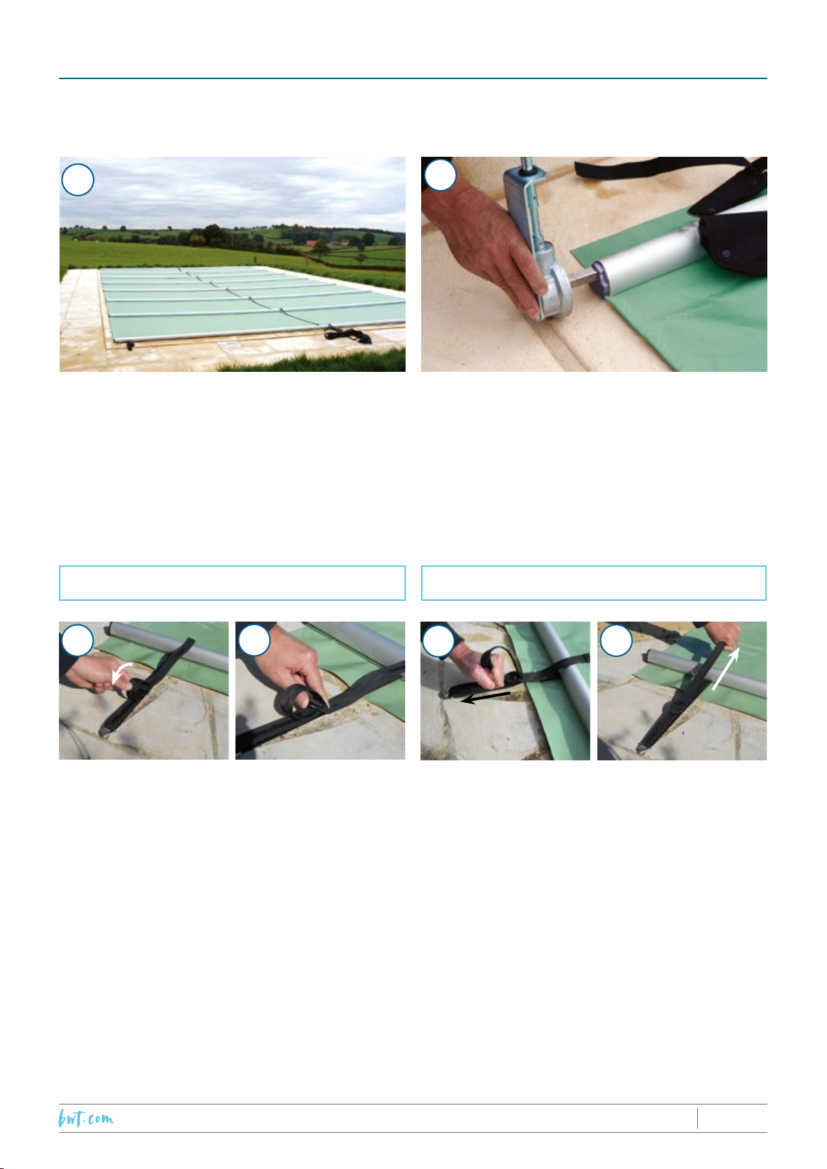
NUMBER OF PEOPLE REQUIRED FOR INSTALLATION:
Usually, two people are needed to carry the cover to the edge of the pool. The
installation itself only requires one person.
INSTALLATION TIME: Between 1 and 2 hours depending on the size of the pool.
A CHILD CAN DROWN IN LESS THAN THREE MINUTES.
NO TYPE OF SAFETY DEVICE COULD REPLACE SUPERVISION AND VIGILANCE OF A RESPONSIBLE ADULT..
TOOLS REQUIRED:
• Electric drill
• Ø10 mm and Ø12 mm concrete drill
bits
• Tape measure
• Flat head screw driver
• • Mallet
CONTACT
PROCOPI HOTLINE
+33 892 69 69 60
(+ access code provided
by your dealer)

2019/06 - Indice de révision : A - Code : 33905PROTECTION & SÉCURITÉ 19/32
1. COVER FASTENING SYSTEM ...................................................................... 20
2. INSTALLING THE COVER............................................................................ 22
2.1 Pools featuring roman steps or straight steps at the end of the pool.............................24
3. USING THE COVER ..................................................................................... 25
3.1 Rolling up the cover .............................................................................................................25
3.2 Unrolling the cover ...............................................................................................................27
4. MAINTENANCE............................................................................................ 29
5. PROTECTION FROM THE WEATHER........................................................... 29
6. WINTERIZING.............................................................................................. 30
7. MAINTENANCE............................................................................................ 30
8. GUARANTEE CONDITIONS ......................................................................... 31

2019/06 - Indice de révision : A - Code : 33905 PROTECTION & SÉCURITÉ
20/32
1. COVER FASTENING SYSTEM
Code and
designation Use Quantity without
steps Quantity with steps Quantity for seperate
element
6409034
Peg with bushing
Ø 6 mm
To hold the step Fixkits 02 or 4 depending on
the width of the step
piece
2, 4 or 6 depending
on the size of the
element
2396011
Fixkit To fasten the step piece 0
Peg with bushing
Ø 8 mm
To hold the tensioning
straps 6 12 3
Tensioning strap Tension the end bars 6 8 3
Cable tensioning strap components:
- 1 Black strap with ring and Superlock buckle / CBE 650 6309010 - 1 dumbell shaped bar code 6409033
End plug To seal the bars 2 per par, except for the roll bar 0
End plug components:
- 1 End plug code 6409042 - 1 cable clip plug, black code 6409049
- 1 Recessed countersunk head screw 6x50 A2 DIN 7982C code 7694350
Drive plug To seal the roll bar and
receive the crank 2 on the roll bar 0
Drive plug components:
- 1 Drive plug code 6409043 - 1 cable clip plug, black code: 6409049
- 1 Recessed countersunk head screw 6x50 A2 DIN 7982C code 7694350
6409007
Coping pad
To protect the fabric
against friction with the
ground
between 2 to 4 per bar 10
6409050
Crank (depends
on the version)
To roll the cover up 1 for covers up to 4.90 m
2 for covers wider than 4.90 m
POOLS FEATURING STEPS ALONG A LENGTH - INSTALLATION OF A STEP PIECE: If the pool features steps
along one of its lengths, install the separate step piece rst, otherwise skip directly to the instructions on the next
page.
Profile
replacing the
coping
Inner pool wall
• Place the separate component above the steps. The axis of the prole replacing the coping should be
10 cm from the inner pool wall (diagram above). Also ensure that the dimensions “D” are identical to
ensure that the prole is correctly positioned.
Step mid-point

2019/06 - Indice de révision : A - Code : 33905PROTECTION & SÉCURITÉ 21/32
• Use the prole replacing the coping as a template to drill two holes (Ø10 mm) in the coping at each end. Attach
the prole to the coping by inserting a retaining staple at either end as illustrated.
• Position the Fixkit bungee cords along each
edge of the step piece. The distance between
Fixkits (E above) should be between 50 and 70
cm. Each Fixkit is held in position by a peg with
bushing (Ø 6 mm).
• Mark the position of the pegs on the deck. Using
a Ø 10 drill bit, drill a hole 70mm deep 30 cm from
the edge of the fabric constituting the separate
element.
• Push a Ø 6 mm peg with bushing into each hole.
• Hook a Fixkit around each peg.
• On the deck, mark the position of the 3 pegs with
bushings that will hold the step tensioning straps
according to the diagram above.
• Drill three holes (Ø12 mm, depth 70 mm) and
drive a Ø8 mm peg with bushing into each hole.
• Attach a step tension strap to each peg.
• Tighten the straps to tension the step piece.
• Slacken the tension on the central strap to avoid
deforming the prole that replaces the coping.
E
E
E

2019/06 - Indice de révision : A - Code : 33905 PROTECTION & SÉCURITÉ
22/32
2. INSTALLING THE COVER
CONDITIONS PREREQUISITE TO INSTALLATION:
• The area 100 cm around the pool must be cleared.
• Paving must be rmly xed to the ground and laid on a concrete apron with a cement content of
350 kg/m3
!IMPORTANT: During installation, and regularly during use, check that the pads protecting the coping
are correctly positioned, that is underneath the bars where they are in contact with the coping. Should
additional protective pads be required to guarantee protection of the cover, these must be put in
position before using the covere.
!The straps may be slid freely along the bars during installation to ensure perfect alignment with the
pegs on the deck.
12
• Place the rolled-up cover along the width of the
pool to be covered (on the side opposite the
steps or roman steps, if any).
This side of the pool will be called the “storage
side”.
• Centre the cover correctly with respect to the
pool.
• From the opposite side, pull on the central strap
to completely unroll the cover.
• Center the cover on the coping.
If a separate element for lateral steps has
already been tted, the cover will rest on the
prole replacing the coping when the cover is
unrolled.

2019/06 - Indice de révision : A - Code : 33905PROTECTION & SÉCURITÉ 23/32
3
Storage side
4
• On the deck, mark the position of the rst 3 pegs
with bushing according to the diagram above.
Dimensions indicated are measured from inside
the pool.
A = peg position for attachment of bar
tension straps
The distance between the points A should be half
the distance between the two end bushings.
• Drill holes for the Ø 8 mm pegs with bushing:
- Use a Ø 12 drill bit, drill depth 70 mm.
• Insert a peg with bushing and drive it in using a
mallet.
Cover
pool axis
5
• On the opposite side, mark the position of the
3 pegs as described previously.
A = peg position for attachment of bar
tensioning strap.
• Drill holes and insert the pegs with bushings as
laid out in step 4. Hook the straps on as described
in step 6.
6
• Hook the bar tension straps onto their respective
pegs and tension. Check that the bars are
parallel to the pool wall, use the straps to adjust
if necessary.
Do not over-tension, this could twist the peg with
bushing; apply the same tension to each of the
three straps.
Cover
pool axis
!Over-tensioning the bar tension straps can lead to the permanent deformation of the bar to which it
is attached.

2019/06 - Indice de révision : A - Code : 33905 PROTECTION & SÉCURITÉ
24/32
2.1 Pools featuring roman steps or straight steps at the end of the
pool
89
pool axis
Cover
!Slide the stair extension with respect to the cover until it is perfectly positioned.
FOLLOW THE DIAGRAM ILLUSTRATED ABOVE FOR POOLS FEATURING STRAIGHT STEPS OR ROMAN
STEPS :
A = peg position for attachment of bar tension straps.
C = Fixkit peg position.
If the step extension measures less than 1.40 m, no Fixkit will be placed in the middle. If the step piece is wider than
1.40 m, place Fixkits at regular intervals. The distance separating two Fixkits should be between 50 and 70 cm.
Examples of other types of step piece at the end of the pool:
Cover Cover
Filter unit

2019/06 - Indice de révision : A - Code : 33905PROTECTION & SÉCURITÉ 25/32
3. USING THE COVER
!
Always keep an eye on the pool when opening and closing the cover.
10 11
3.1 Rolling up the cover
FOLLOW THESE STEPS:
1 - Position the strap used to unroll the cover: bring the long central strap down the middle of the pool to
the “storage” side.
2 - Unhook the tensioning straps (photos 12a to 12d) : On the side opposite the storage side, slacken and
unhook all the tensioning straps.
TO TENSION THE TENSIONING STRAPS
12c 12d
Take a rm hold of the
strap and pull it toward
the peg until it is fully
tensioned.
Once tensioned, pull
the end of the strap to
lock it in position. This is
necessary to maintain
tension on the straps.
12a 12b
Slacken the top part
of the strap, creating a
loop.
Flip the Superloc toward
the cover, the strap will
slacken automatically.
TO RELEASE THE TENSIONING STRAPS
!
Carry out the tensioning (12c) and locking (12d) operations very carefully to ensure that the pool is
correctly secured.

2019/06 - Indice de révision : A - Code : 33905 PROTECTION & SÉCURITÉ
26/32
3 - Ensure that the bushings have retracted into their lower position to avoid hurting your feet.
4 - Before rolling up the cover, make sure that the long central strap used to unroll the cover is secured as
shown in the diagram below. To do this, thread the loose end of the strap on the part of the quick disconnect
fastener that is detachable from the cover around the buckle on the part of the fastener permanently
attached to the cover. This will prevent the strap from falling into the pool in the event that the fastener
opens accidently or breaks the next time that the cover is unrolled.
Unrolling strap - Removable section
First bar of the
CBE 650 cover
Quick disconnect fastener -
Female half
3-way buckle
Quick disconnect fastener -
Male half
Unrolling strap - Fixed section
5 - Insert the crank. The stainless steel square drive should be fully inserted into the end plug designed
for this purpose.
!
Failure to fully insert the square drive can result in the deformation of or damage to the end plugs.
!Never force on the crank, this could twist or even break it.
Keep the cover taut and the bars parallel to each other while rolling to ensure
that the cover rolls up evenly.

2019/06 - Indice de révision : A - Code : 33905PROTECTION & SÉCURITÉ 27/32
!The cover should be rolled up slowly and as evenly as possible. Particular attention should be paid
when rolling the bars, if the cover is allowed to fall sharply against the coping, the fabric could, due
to the weight of the cover, suffer permanent damage at the points where it is caught between the bar
and the coping.
!In the event that the cover rubs against the crank while rolling, stop and correct this. Proceeding under
these circumstances can lead to premature abrasion of the cover edges.
On encountering difculty rolling up the cover towards the end of the cover or at the bars:
Pull the crank down towards the uncovered side of
the pool while continuing to wind the crank.
Then, while holding the crank rmly, push it
towards the pool in the opposite direction
continuing, if possible, to wind the crank to
faciliate rolling up of the cover.
!
Large pools (width greater than or equal to 4.90m) require a second crank (obligatory) that must be
inserted into the other end of the bar around which the cover is rolled and wound by a second person.
Furthermore, the two cranks must be wound in a synchronised manner such that the cover is rolled up
evenly.
3.2 Unrolling the cover
1 - Take hold of the central strap, walk to the other side of the pool and position yourself in the middle facing
the storage side, then pull on the strap to unroll the cover .
When unrolling cover, adopt the position illustrated
above keeping your weight on your back foot.
This will prevent you from falling into the pool in
the event that an element of the strap fails and
the strap becomes detached from the cover. This
recommendation is especially important if the
strap was not secured as described previously
(refer to: section Rolling up the cover).

2019/06 - Indice de révision : A - Code : 33905 PROTECTION & SÉCURITÉ
28/32
!The central unrolling strap should only be used to unroll the cover. It should under no circumstances
be used to tension or reposition the cover. Using the strap for any purpose other than the purpose for
which it was designed can lead to failure of the quick disconnect clip attaching the long section of the
strap to the cover. To tension or reposition the cover on the pool, take hold of the end bar and lift the
cover before moving it;
!Failure to abide by these instructions can lead to the abrasion of the cover fabric at the points where
it is in contact with the coping.
2 - Pull on the central strap to unroll the cover. Ensure that the cover rools out correctly over the pool.
!The cover should be unrolled slowly and carefully. Particular attention should be paid when rolling the
bars, if the cover is allowed to fall sharply against the coping, the fabric could, due to the weight of
the cover, suffer permanent damage at the points where it is caught between the bar and the coping.
3 - Attach and tension the tensioning straps.
!NOTE: Daily manipulation of the CBE 650 cover (rolling up - unrolling) entails multiple repeated
contacts both between the various elements of the cover and with the ground. Dust, detritus, even
sand or gravel can accumulate on the cover, adding to the friction. It is therefore normal to observe
tarnishing, scratches and wear on those sections of the cover (fabric and bars) most exposed to
friction. Similarly, traces of PVC may appear on the coping. These phenomena shall not be considered
a manufacturing defect and are not covered by any guarantee.
FOLLWING INSTALLATION :
Ensure:
• that the straps are correctly tensioned.
• that the cover is correctly centred with respect to the coping.
• that no folds have formed in the cover at the points where it is in
contact with the coping, folds increase the risk of abrasion.
The long central strap used to unroll the cover may be removed (13)
and stored if the cover is to be left on the pool for a long time.

2019/06 - Indice de révision : A - Code : 33905PROTECTION & SÉCURITÉ 29/32
4. MAINTENANCE
The user is entirely responsible for the correct maintenance of his/her CBE 650 cover.
CLEANING THE COVER:
Cleaning methods:
• High pressure cold water jet: Hold the cleaning nozzle at least 40 cm away from the cover.
• COVERNET detergent (Code 8880505): spread the detergent on the cover and brush lightly with a
nonabrasive soft bristle brush. Allow it to act for 2 minutes and rinse with water.
The CBE 650 cover must be cleaned regularly, at least twice a year. (At the beginning and end of winterizing).
5. PROTECTION FROM THE WEATHER
Rain:
Check regularly, if possible each time it starts to rain, that the rain water drainage holes are not blocked by
leaves or any other debris. Remove any material blocking these holes immediately.
The pool must be fitted with an overflow to evacuate water that can accumulate as a result of heavy
precipitation.
In the case of free form pools, the natural bend of the bars will differ depending on the bars position
on the pool. Given this phenomenon, it is possible that the drainage holes made in the factory will not
suffice. Under such circumstances, note the areas where water is inclined to accumulate when the cover
is installed and tensioned and, using a hole punch, make a hole Ø 16 mm in this area.
Snowfall:
The average density of fresh snow is 110 kg/m3, how-ever snow density increases with increasing snow
temperature and can be up to 4 times higher at the rain-snow temperature boundary (wet snow).
Thus, a blanket of snow 10 cm deep lying on a cover 9 m X 4 m would weigh at least 400 kg.
To avoid the irreversible deformation of the bars, remove snow from the cover as quickly as possible.
Ideally, roll the cover up as soon as it starts to snow.
The CBE 650 cover meets the requirements set out in the French standard NFP 90-308 (Certification
awarded by the French test laboratory- LNE). While these requirements stipulate that the cover
must support the weight of an adult (100 kg). The cover is not, how-ever designed to bear the
weight of a blanket of snow.
Installation of the Calypso winterizing kit (available as as option) is highly recommended.This kit
increases the covers ability to withstand fortuitous excessive weight loads.
Strong winds:
Ensure that the straps and cables are correctly tightened and that the wind cannot lift the cover and cause
it to flap against the coping.
Following exposure to extreme wind, snow or wind conditions, check the tensioning straps, bushings,
cables and buckles to ensure that they have not been loosened or sustained any damage.
Heat:
Avoid contact between the cover and objects hotter than 75°C.

2019/06 - Indice de révision : A - Code : 33905 PROTECTION & SÉCURITÉ
30/32
6. WINTERIZING
Winterizing
While wintering it is absolutely vital that the water level be maintained at least 2/3 of the way up the
skimmer. To ensure that this criterion is met, we recommend that you consult with a professional. Empty
water lines by blowing them with compressed air, plug water returns and insert gizmos into the skimmers.
During the winter period:
• every 15 days, check that the cover is correctly tensioned (the strips of material should be almost at)
this will help prevent water pockets from forming during heavy rain fall.
• follow the steps outlined above concerning protection against the elements.
• ensure that the holes provided to allow rain water to drain away have not been blocked (leaves,
branches, any other matter, etc.)
• check that the attachment system is not subject to any continual or prolonged abnormal stress or
tension. Remove any matter that collects on the cover (leaves, water, etc.).
• Ensure that the attachment system is correctly fastened and in good condition, capable of maintaining
cover tension. Correct tension on the cover will lengthen the cover’s service life and ensure optimum
protection of children.
!A winterizing kit is available as an option. This kit helps the cover bear the weight of short term loads
(snow, large pile of leaves, heavy rain, etc.).
7. MAINTENANCE
CHECK:
At least twice a year, (at the beginning and end of wintering), inspect the following items very carefully:
• bar tensioning straps.
• Pegss with bushings.
• Coping pads.
Replace any badly worn items that would be likely to prevent correct positioning of the cover immediately.
Periodic replacement:
Replace the tensioning straps systematically every four years. To guarantee safett, use original straps only.
The coping pads are designed to protect the cover against abrasion at the points where it is in contact with
the ground. The rate at which these protective pads are worn will depend on the roughness of the ground
surface and the frequency with which the cover is rolled out and rolled up. They should be replaced at least
once a year.

2019/06 - Indice de révision : A - Code : 33905PROTECTION & SÉCURITÉ 31/32
Stitching
Stitching
Stitching
Superlock buckle, black
Triangular ring, diam 5 x 25
Strap
DESIGNATION
Tensioning strap routing
8. GUARANTEE CONDITIONS
The cover fabric is protected by a 2 year guarantee that covers the integrity of the welded seams and
the cover fabric’s ability to withstand exposure to UV light The aluminium bars are covered by a two year
guarantee against corrosion and degradation of the nishing lacque.
Wear parts and mechanical parts (plugs, coping pads, straps, cam buckles, ratchet buckles, dee and
twisted shackles three-way buckles and sleeves) are guaranteed 6 months.
The following are not covered by any guarantee:
• permanent deformation of the bars caused by subjecting the cover to excessive loads (refer to the
paragraphs “Protection against the weather” and “winterizing”;
• The fabric pocketing phenomenon.
• The wear of any element subjected to friction, rubbing or stamping (refer to the section “using the
cover”).
• Discoloration of the fabric associated with excessively high concentrations of disinfectants or treatment
chemicals.
And, more generally, any damage directly or indirectly attributable to the installation ,use or
maintenance of the cover other than in accordance with the instructions provided in this document.
!COMMENT: Temporary discoloration of the fabric may be observed on contact with water, this
phenomenon is normal and is not included in the scope of the guarantee.

2019/06 - Indice de révision : A - Code : 33905 PROTECTION & SÉCURITÉ
32/32
3 566837 145071
Table of contents
Other BWT Lighting Equipment manuals
Popular Lighting Equipment manuals by other brands

thomann
thomann Stairville Quad Par Profile user manual

Laserworld
Laserworld EL-500RGB KeyTEX manual

RZB Lighting
RZB Lighting GSUN-S Instruction

Manaras Opera
Manaras Opera Lightcurtain 003 Specification and installation instructions

Strand Lighting
Strand Lighting 100 Operation manual

VS LIGHTING SOLUTIONS
VS LIGHTING SOLUTIONS LiCS OUTDOOR iCTT Mounting instruction