BYD B-Box 12.8 User manual

B-BOX 12.8 installation guidance
1/ 30
Installation Guidance
B-BOX 12.8
Version:2.0
Update:20160610

B-BOX 12.8 installation guidance
2/ 30
1 Preface ...................................................................................................................................4
2 Information in this Guidance...............................................................................................4
2.1 About this guidance............................................................................................................................... 4
2.2 Target Group........................................................................................................................................... 4
2.3 Additional Information............................................................................................................................ 4
2.4 Symbols Used......................................................................................................................................... 4
3 Safety......................................................................................................................................5
3.1 Warnings and Notification..................................................................................................................... 5
3.2 Safety Guidelines................................................................................................................................... 5
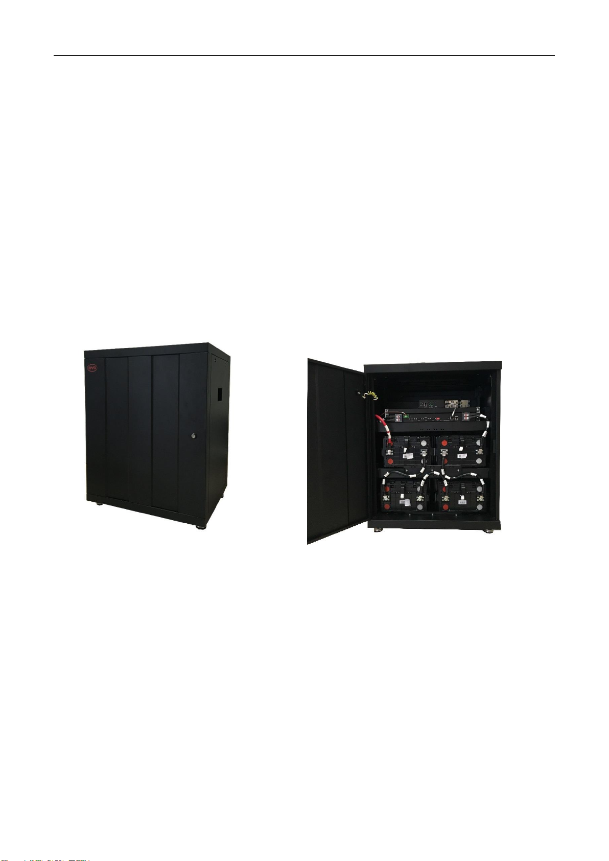
4 Product Overview .................................................................................................................6
4.1 Product Introduction............................................................................................................................... 6
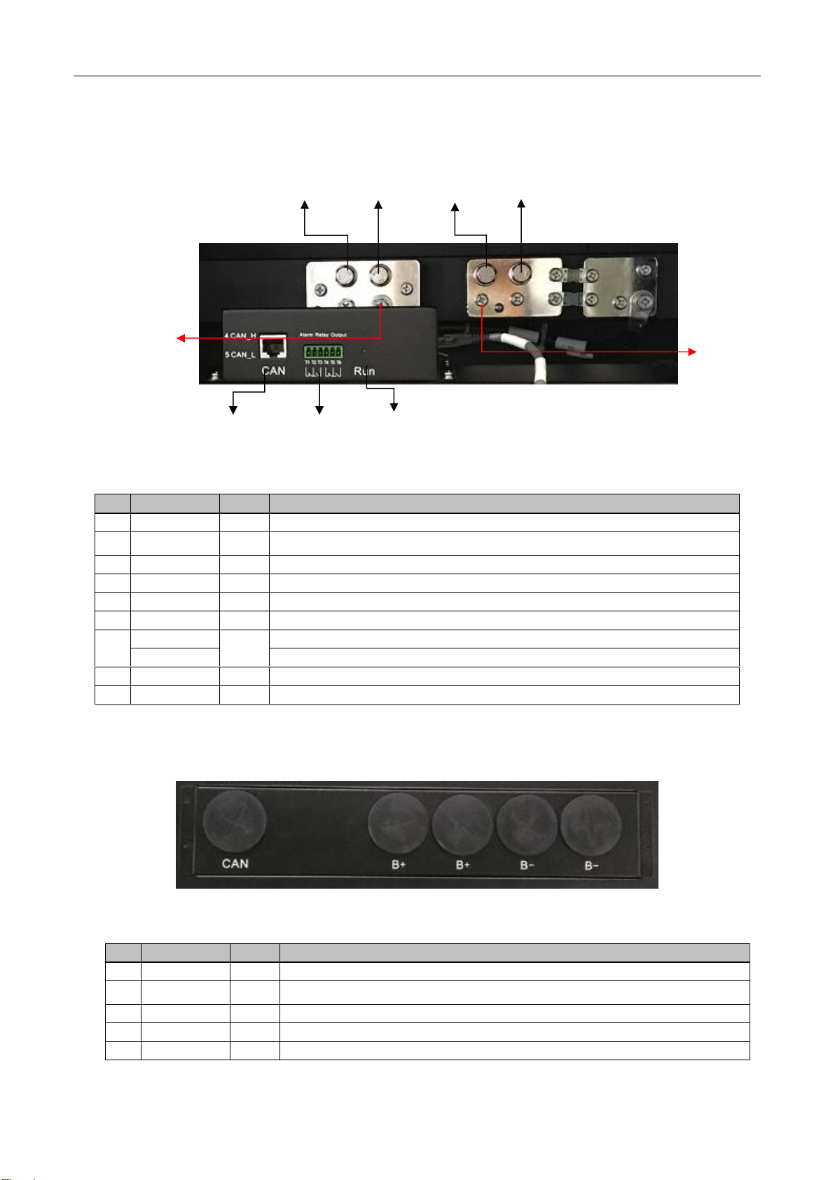
4.2 Terminal introduction............................................................................................................................. 7
4.2.1 Cabinet internal terminal introduction.................................................................................................. 7
4.2.2 Cable outlet of cabinet........................................................................................................................... 7
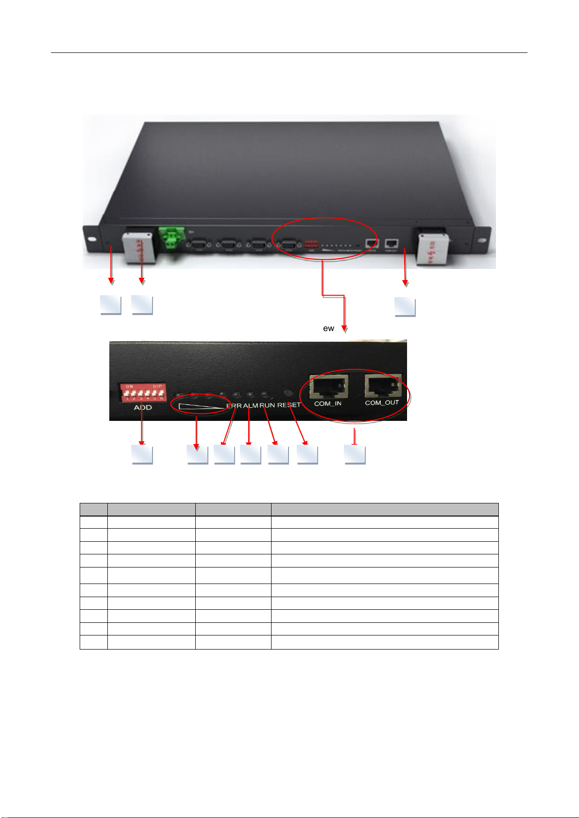
4.2.3 BMS interface and terminal introduction............................................................................................. 8
4.3 Identifying The Product......................................................................................................................... 9
5.2.2 Configuration list of B-BOX with different inverter........................................................................ 9
5.2.2.1 B-BOX configuration list with SMA sunny island ................................................................................. 9
5.2.2.2 B-BOX configuration list with GOODWE ES inverter ...................................................................... 10
5 System Installation.............................................................................................................10
5.1 Installation notice.................................................................................................................................. 10
5.2 Package information and system configuration list......................................................................... 11
5.2.1 Configuration list................................................................................................................................... 11
5.2.3 Installation Tools................................................................................................................................... 12
5.2.4 Part list ................................................................................................................................................... 12
5.2.5 Personal protective equipment........................................................................................................... 13
5.3 Installation............................................................................................................................................. 14
5.3.1 Open the package................................................................................................................................ 14
5.3.2 Disassemble the pallet......................................................................................................................... 14
5.3.3 Anchor bolt installation......................................................................................................................... 15
5.3.4 Battery installation................................................................................................................................ 15
5.4 More cabinet installation..................................................................................................................... 20
5.4.1 Communication cable connection drawing....................................................................................... 20
5.4.3 Power cable connection between B-BOX and inverter(with combiner box)................................ 20
5.4.5 Parallel connection cable suggestion................................................................................................ 21
5.5 BMS address set up ............................................................................................................................ 22
6 Start system.........................................................................................................................22
6.1 System activity procedures when B-BOX connect to SMA Sunny island ................................... 22
6.2 System activity procedures when B-BOX connect to GOODWE ES........................................... 24
7 Stopping the system ..........................................................................................................25
7.1 Stopping the system when B-BOX working with SMA SUNNY ISLAND..................................... 25
7.2 Stopping the system when B-BOX working with GOODWE inverter........................................... 26
8 Normal alarm and solution for first installation .............................................................26
8.1 Normal alarm and solution display on SMA sunny island SRC.................................................... 26

B-BOX 12.8 installation guidance
3/ 30
8.2 Normal alarm and solution display on BMS..................................................................................... 28
Appendix 1..............................................................................................................................29
Appendix 2..............................................................................................................................30

B-BOX 12.8 installation guidance
4/ 30
1 Preface
Thank you for choosing BYD products. We will provide you good quality as well as reliable after service.
To protect using staffs and product, please kindly read this manual carefully which provide detailed
information for products’ features, structures, operate standard, maintenance and troubleshooting.
Special announcement:
This manual can’t be taken as basis of requirement for BYD.
BYD hold the final explanation right of this manual.
2 Information in this Guidance
2.1 About this guidance
This is the installation guidance for the BYD battery box products- B-Box 12.8. User of this device or
installer must refer to the installation guidance to installation and using correctly.
2.2 Target Group
This installation guidance applies only to the BYD battery box products-B-Box12.8.
2.3 Additional Information
Specification of the product can be changed without any notice to customers for the system improvement.
2.4 Symbols Used
Symbols meanings:
CAUTION:
CAUTION represents hazardous situations which can cause light injuries if not
avoided.
NOTICE:
NOTICE represents the situations which can cause damage to property if not avoided.

B-BOX 12.8 installation guidance
5/ 30
INFORMATION:
INFORMATION provides tips that are valuable for optimum installation and operation
of the product.
3 Safety
3.1 Warnings and Notification
Installation environment requirements: BYD B-Box 12.8 is designed for household purposes. For
installation, it must be installed in a location complying with IP20. If the Installation location does not comply
with IP20 may cause failure and the product will not be guaranteed for any related accident or damage.
3.2 Safety Guidelines
CAUTION:
Li-Ion battery (energy storage unit) inside.When assembling the system, do not intentionally make a short
condition between the positive (+) and negative (-) terminals of the battery box with a metallic object.
All work on the B-Box and electrical connections must be carried out by qualified personnel only. B-Box
provides a safe source of electrical energy when operated as intended and as designed.
Potentially hazardous circumstances such as excessive heat or electrolytemist may occur under improper
operating conditions, damage, misuse and/or abuse. The following safety precautions and the warning
messages described in this section must be observed. If any of the following precautions are not fully
understood, or if you have any questions, contact Customer Support for guidance. The Safety Section
may not include all regulations for your locale; personnel working with B-Box must review applicable
federal, state and local regulations as well as the industry standards regarding this product.
Installation personnel can not wear watches, etc., to avoid short circuit and human damage.
CAUTION:
Due to high weight of BYD B-Box 12.8, please use hard package and do safety protection when
transport, please also pay attention to the safety to avoid human damage.

B-BOX 12.8 installation guidance
6/ 30
4 Product Overview
4.1 Product Introduction
BYD battery box products B-Box12.8 as the energy storage parts can be used in off-grid & on-grid
energy storage system.
It is recommended not to use this device for other than the purpose described in this guidance. The
substitute use of this product, random change, and use of components other than sold or recommended
by BYD will nullify the product guarantee. It also support parallel connection between B-Box with
maximum number 32, the total capacity can reaches to 409kWh.
The system is easy for installation and maintenance.
Figure 1 Over view of B-BOX
Figure 2 Internal view of B-BOX

B-BOX 12.8 installation guidance
7/ 30
4.2 Terminal introduction
4.2.1 Cabinet internal terminal introduction
Table 1 Terminal compare list
No.
Interface
Mark
Function
B+
/
Connect to battery in cabinet, each terminal can connect 1~2 battery
B-
/
Connect to battery in cabonet
P+
/
Connect to inverter
P-
/
Connect to inverter
P+
/
Connect to another B-BOX or Combiner box
P-
/
Connect to another B-BOX or Combiner box
CAN port
CAN
Connect to inverter CAN port.
RS485
Update sw
Dry contact
Dry contact application, output alarm info.
Run led
Run
Indicate the B-BOX running status
4.2.2 Cable outlet of cabinet
Figure 4 Top through-holes
Table 2 Compare list of through-holes:
No.
Interface
Mark
Function
CAN
CAN
Pass the CAN communication cable
B+
B+
Pass the positive cable from another B-BOX
B+
B+
Pass the positive cable from inverter
B-
B-
Pass the negative cable from inverter
B-
B-
Pass the negative cable from another B-BOX
Figure 3 Terminals of B-BOX

B-BOX 12.8 installation guidance
8/ 30
4.2.3 BMS interface and terminal introduction
Figure 5 BMS overview
Figure 6 Display and communicate interface
Table 3 Display and communicate interface
No.
Interface
Mark
Function
①
B+
B+
Connect battery positive cable to power the BMS
②
B-
B-
Positive terminal of BMS
③
P-
P-
Negative terminal of BMS
④
SOC LED
SOC
Indicate State of capacity of battery
⑤
RUN LED
RUN
Indicate the Plus is running status
⑥
ERR LED
ERR ADDR
Indicate error status
⑦
Alarm LED
Alarm
Indicate alarm status
⑧
RJ45 terminal
RS232/RS485
Communication ports
⑨
Address
ADDR
When parallel connection, need setting address.
⑩
Reset
RESET
Activity battery when no external power add on battery.
⑩
③
①
②
④
⑤
⑥
⑦
⑩
⑨
⑧

B-BOX 12.8 installation guidance
9/ 30
4.3 Identifying The Product
The Type Label describe the product identity and attached on the product. For safe usage, the user
must be well-informed of the contents in the Type Label. The Type Label includes:
Product Name:
Product Type:
Rated output voltage:
Rated current:
Operation temperature range:
Serial Number (P/N No.):
Caution:
Certification marks:
5 Configuration list of B-BOX with different inverter
5.1 B-BOX configuration list with SMA sunny island
1 Phase on Grid
Inverter Type
B-Box 12.8
Cabinet
SI 3.0M
≥1
≥1
SI 4.4M
≥1
≥1
SI 6.0H
≥1
≥1
SI 8.0H
≥1
≥1
Remark: Maximum B-Box12.8 quantity is 32.
3 Phase on Grid
Inverter Type
B-Box 12.8
Cabinet
SI 3.0M
≥3
≥1
SI 4.4M
≥4
≥1
SI 6.0H
≥4
≥1
SI 8.0H
≥4
≥1
1 Phase off Grid
Inverter Type
B-Box 12.8
Cabinet

B-BOX 12.8 installation guidance
10 / 30
SI 3.0M
≥3
≥1
SI 4.4M
≥3
≥1
SI 6.0H
≥5
≥2
SI 8.0H
≥5
≥2
3 Phase off Grid
Inverter Type
B-Box 12.8
Cabinet
SI 3.0M
≥8
≥2
SI 4.4M
≥8
≥2
SI 6.0H
≥12
≥3
SI 8.0H
≥12
≥3
Remark: Maximum B-Box12.8 quantity is 32.
5.2 B-BOX configuration list with GOODWE ES inverter
1 Phase on Grid
Inverter Type
B-Box 12.8
Cabinet
4.6kW
≥1
≥1
1 Phase off Grid
Inverter Type
B-Box 12.8
Cabinet
4.6kW
≥1
≥1
Remark: Maximum B-Box12.8 quantity is 32.
6 System Installation
6.1 Installation notice
a) Before installation, check the battery open circuit voltage.
b) Battery installation location should be away from heat and avoid produce spark. The safety
distance should be above than 0.5m.
c) Battery installing connecting cables should be as short as possible, to prevent excessive line

B-BOX 12.8 installation guidance
11 / 30
pressure drop.
d) Batteries with different capacity, different P/N or different manufactures are not allowed for
connection.
e) Before conducting the battery, the battery positive and negative poles need to be carefully
checked as well to ensure correct installation.
f) The mounting floor should be horizontal.
6.2 Package information and system configuration list
The cabinet and battery are packaged separately with cartons, the components are taken along with the
cabinet or battery package , before installation, installer should read the system configuration list.
B-BOX Cabinet B-Plus12.8
6.2.1 Configuration list
Please install B-BOX12.8 according to table1.
Table 1 Basic configuration list
Type
B-BOX 12.8
B-BOX cabinet
1
B-Plus 12.8
2 package(4 battery module)
User manual
1
Positive cable
1

B-BOX 12.8 installation guidance
12 / 30
Negative cable
4
Communicate cable
1
Signal cable
4
6.3 Installation Tools
Table 3 Installation tools list
Cross screwdriver
M3~M10
Flat tip screwdriver
M3~M6
Sockets spanner
Diagonal cutters
Adjustable wrench
Knife
6.4 Part list
6.4.1 Part list of cabinet
No.
Item Description
Qty
Purpose
Picture
1
Anchor bolt
4
Make a distance from
cabinet to ground.
2
Positive cable
1
Battery P+ connection
3
Negative cable
4
Battery P- connection

B-BOX 12.8 installation guidance
13 / 30
6
User Manual
1
System information and
using method and
Warranty items.
\
7
Installation Manual
1
System installation
guidance
\
Remark: This part list is only for one system cabinet.
6.4.2 Part list of B-Plus 12.8
No.
Item Description
Qty
Purpose
Picture
1
Battery module
4
Installed into cabinet
Remark: This part list is only for one B-BOX 12.8..
6.5 Personal protective equipment
Insulating shoes
Insulating gloves

B-BOX 12.8 installation guidance
14 / 30
6.6 Installation
6.6.1 Open the package
Tools: Knife
6.6.2 Disassemble the pallet
a) Lay down the cabinet, in order to prevent scratches cabinets, please do protection on the ground.
b) Take away the four screws which installed on the root of the pallet.
c) Take away the pallet.
Tools : Adjustable Spanner

B-BOX 12.8 installation guidance
15 / 30
d) Take the battery out of the wooden casing,and put the four battery modules a certain distance from
the cabinet.
6.6.3 Anchor bolt installation
Install the 4pcs anchor bolt into the four hole in bottom of cabinet.
Tools : Adjustable Spanner. Fixed torque: 10±1Nm
i. Install the anchor bolt, turn the anchor bolt to the certain height;
ii. Using Spanner to turn the second screw to lock the anchor bolt;
iii. Move the first screw to the cabinet bottom closely;
6.6.4 Battery installation
Tools : Cross screwdriver
Install step:
iv. Move the cabinet to the installation place, prepare to install battery.
v. Open the door, take away the part bag from the battery storey.
vi. Disassemble the dam-board from cabinet.
vii. Pull the battery module into cabinet.
Note:
Each layer only can install two battery modules. Installer should install the battery from the bottom layer to the
top layer.
Should keep the label side toward up.

B-BOX 12.8 installation guidance
16 / 30
Pull the battery into cabinet All battery modules had pulled into cabinet
6.6.5 System cables connection
Connect cables refer to below figure7, should connect from 1~10 strictly.
The battery can only in series connection.
Do not short connect, reverse polarity connect, take care of insulation.
Parts
Negative cable
Negative cable 1
Negative cable 2
Sampling cable
Communicatio
n cable(BMS to
BMU)
Dam-board

B-BOX 12.8 installation guidance
17 / 30
a) Connect the negative cable (Black cable from cabinet) to the “P-“ of battery, refer to step 1~4 in figure
Tools: Cross screwdriver, Fixed torque: 20±2kgf.cm
b) Connect the positive cable (Red cable from cabinet) to the “P+“of battery, refer to step 5 in figure
Tools: Cross screwdriver, Fixed torque: 20±2kgf.cm
c) Sampling cable connection
Connect the sampling cable terminal of battery and BMS which marked in figure 8 :
Mark: Check the sampling terminal are firm installed.
1
2
3
4
5
6~9
10
Figure 7 Cable connection order

B-BOX 12.8 installation guidance
18 / 30
Figure 8 communicate terminal of battery
Figure 9 communication terminal of BMS
Sampling
Terminal

B-BOX 12.8 installation guidance
19 / 30
Figure 10 communication cable connection view
d) BMS B+ connection
Operator only need to connect the positive cable lead from P+ DC BUS to “B+” terminal on BMS.
Tools: Flat tip screwdriver, Fixed torque: 2.5±0.5kgf.cm
As show in figure 11, find the positive cable and the B+ terminal.
Figure 11
Take off the left screw on B+ terminal by screw driver, then put the battery positive cable into the
terminal, at last lock the screw again.
Battery positive
cable—Brown color
B+ terminal

B-BOX 12.8 installation guidance
20 / 30
Figure 12 B+ terminal connection
6.7 More cabinet installation
When user need more than one cabinet to install, should repeat above operations.then do parallel connections
between cabinet.
6.7.1 Communication cable connection drawing
6.7.2 Power cable connection between B-BOX and inverter(with combiner box)
Notice: All the cables should have same length.
Screws
Table of contents
Other BYD Batteries Charger manuals
Popular Batteries Charger manuals by other brands

NOCO Genius
NOCO Genius GENIUS1 User guide & warranty

fontastic
fontastic OVIN user manual

Duosida
Duosida SES-32-3 installation manual

Starkey Hearing Technologies
Starkey Hearing Technologies VFusion user manual

Panasonic
Panasonic Lumix DMW-BTC13 operating instructions

Metabo
Metabo ASC 30-36 Original instructions