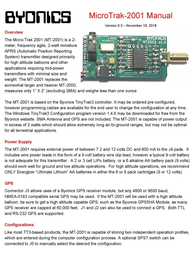
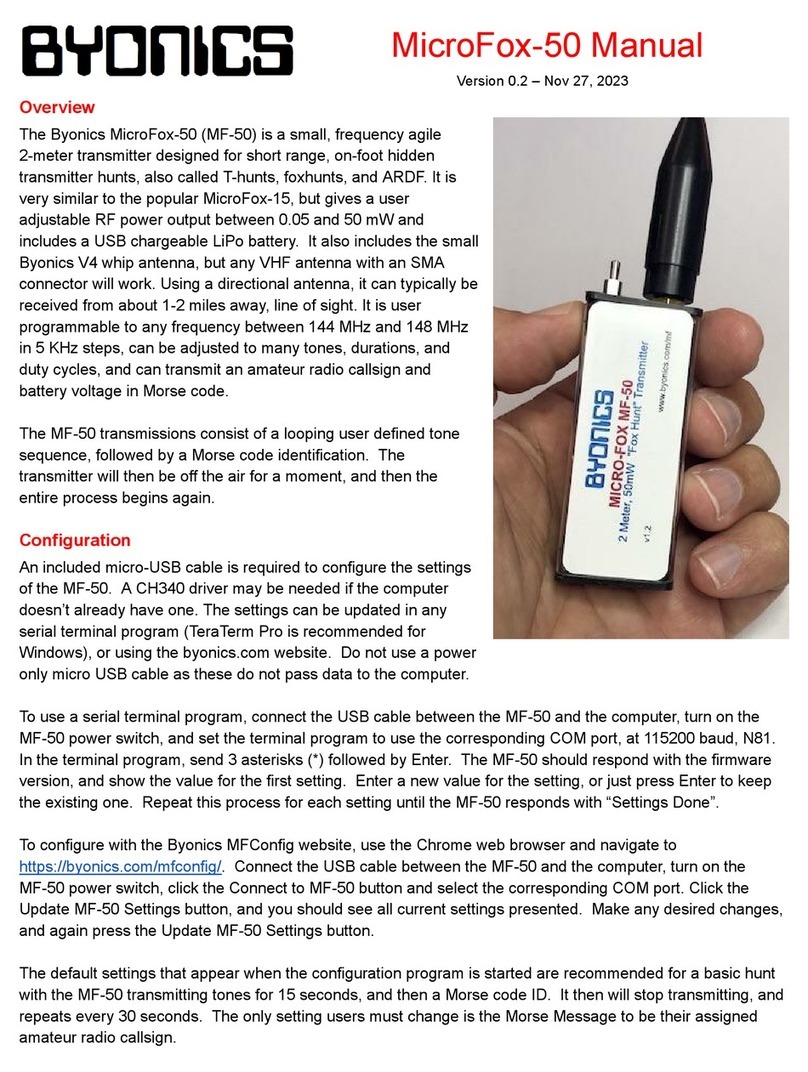
BYONICS MT-AIO User manual

Micro-Trak All-In-One APRS Transmitter
Hardware version 3.2
The MT-AIO is a self-contained, water resistant
APRS transmitter/GPS receiver designed for portable
use. The MT-AIO is computer programmable, and
frequency agile over the entire 2 Meter ham band.
Operation beyond 2 Meter bandwidth limits are not
supported, since the device is not FCC approved for
use outside the ham bands. Agencies exempt from
FCC requirements may contact us about out of band
operations. The device is rugged, and intended for
operation using 8 conventional AA batteries or other
battery packages available locally that do not exceed
13.6 volts. Although the MT-AIO is water resistant,
and uses door gaskets, and O-rings to maintain water
resistance, it is not designed to be submerged.
The MT-AIO is a transmitter only, and may send
packets coincidentally with other transmitters. We
recommend using the MIC-E format (default) with this transmitter, since shorter packets
tend to have a higher throughput, save power, and minimize potentially high RF exposure
levels.
The MT-AIO is controlled by a special version of the TinyTrack 3 chip, and retains most,
but not all, of the special functionality of the TT3. Features intended primarily for HF
operation have been omitted, for instance. Special features of the MT-AIO include a
power saving mode that switches the GPS on and waits for a locked GPS position before
sending a transmission. Since the MT-AIO draws only a few milliamperes in the standby
mode, battery life can be extended to days or weeks, depending upon the transmission
rate selected and other parameters, including the type of data packet sent.
Power output of the Micro-Trak AIO is adjustable, and may be dialed down to a few
hundred milliwatts of power or up to as much as 10 Watts. It is shipped set to maximum
power.

USER CONTROLS
Switches
The selector switch, located near the center of the PC
board, is a two position switch. Even when left off, the
batteries should be removed for extended storage to
prevent leakage and damage to the device.
The other switch, shown in the lower right hand corner
of the Printed Circuit Board, is for selecting one of the
two configurations stored in the TT3 chip’s memory.
The two pages of configuration selection allow you to
enter different frequencies, icons, transmission rates,
FCC call signs, tactical call signs, beacons, and all other
programmable features.
The MT-AIO will ordinarily be shipped
programmed with the customers requested
parameters, allowing instant on-the-air operations; just add batteries.
On moving the switch to the channel 1 or channel 2 positions, the device will send a
transmission. This data may not immediately include valid GPS data, since the GPS will
not have had time to synchronize. Subsequent transmissions will wait for the GPS to
acquire lock, and this may cause transmissions to be sent at intervals different than those
programmed into the device. For instance, if you select 2 minute transmission intervals
(the default option) and enter a cave, the GPS will not “synch up”, preventing a
transmission. Immediately upon “waking up” from its sleep cycle, the GPS will be
activated, and a transmission will occur as soon as the GPS determines a valid position
fix.
Deviation Control
Two small blue trimmer potentiometers are located on the printed circuit board. One is
marked “DEV”. This is the deviation control. The deviation control is fixed so that at
maximum rotation, deviation does not exceed 4 KHZ, which is well within the range of
most digipeaters. Commercial receivers may require a narrower signal, and this control
can be used to allow better decoding in these receivers.

Power Control
The power control is the other blue trimmer potentiometer. It is set fully clockwise from
the factory for maximum power. This trimmer sets the gate voltage on the amplifier
module to allow power control over a wide range, but it is important to remember that
this controls’ range is all within a few degrees of fully clockwise. Power adjustments are
best made using a wattmeter and dummy load. The power adjustment may also be used
when programming your MT-AIO with your computer. Turning the power all the way
down will minimize problems in programming caused by RF energy “swamping” your
computer or USB to serial adaptor.
Antennas
The Micro-Trak AIO is shipped with a high quality 2 Meter whip antenna. For portable
use, this is a great option. Take care not to bend the base of the antenna, as this can result
in a cracked enclosure or broken PC board. External antennas may be utilized, but care
should be taken to ensure that the SWR is within best practices, and that the antenna is
not in too close a proximity to other transmitters or static fields, as this can damage the
final amplifier. Operating without an antenna will destroy the final amplifier. For this
reason, final amplifiers are not covered under warranty, and repairs will be subject to
parts and bench tech costs.
Status LED
A single bi-color LED is used to show the status of the unit. Immediately upon start up,
the LED will flash a pattern of red and green, indicating that the unit is starting up and
internally resetting. If this pattern continues without stopping, this is an indication that
something is wrong, such as a low battery state or excessive SWR. The single pulse of a
red signal indicates that the unit is sending a transmission. A blinking green indicates that
the unit has switched on the GPS and is waiting for it to lock onto the GPS satellites.
When the GPS locks on solidly, the TT3 processor will allow the transmitter to send its
data out over the air, causing the GPS green indicator to switch off. In some cases, the
GPS LED will remain lit until the next timing cycle. This is normal, and is an attempt by
the TT3 to verify good GPS data.

Programming
Ordinarily, the MT-AIO is shipped pre-programmed with the user’s information. In the
event that a user needs to reprogram the MT-AIO, this can be accomplished in several
ways. A MT-AIO Programming cable is available through Byonics for this device. The
programming jack is a 2.5mm, 3 conductor jack located on the lower left hand corner of
the P.C. Board.
The Micro-Trak AIO is configured with the latest TinyTrak3 Configuration software,
which may be downloaded from the Byonics website. Additional information on
programming parameters may be found in the TinyTrak3 Configuration manual. Note
that not all functions are available in the standard TT3 configuration are available for use
on the MT-AIO. PLEASE NOTE: MT-AIO users should typically check the Power
Switch Enable box in the TinyTrak3 Config program to allow the GPS to power down
between transmissions. 3 seconds is a reasonable switch time to use. Failure to check
this will result in much shorter battery life.
Alternatively, the PIC may be removed and plugged into a regular TT3 for programming,
using a null modem cable and a gender changer. Note that there is a difference in the
chips, and the TT3 should not be connected to a radio while programming!
The configuration allows for sending continuous test tone transmissions. These should
not be sent for more than a few seconds at a time, as the MT-AIO power amplifier is not
heat synced for long transmissions.
New Features
Please note that this is the newest generation of Micro-Trak Products, and older
configuration software will not be compatible. Also, this generation of Micro-Trak
products uses a far more powerful processor, and among its many features, it will allow
you to load new or special versions of the Micro-Trak firmware as improvements become
available. This version of the Micro-Trak AIO has built in telemetry sensors to measure
and report the battery voltage on the Micro-Trak, as well as the temperature. An optional
set of inputs is available just below the IC socket, and can be used to report the status of
any 0-5 Volt sensor.

Battery operation
The MT-AIO includes a standard 8 pack AA holder. This connects to the PCB using a
standard 9 volt style battery clip. This clip notwithstanding, the device will not
satisfactorily run on a 9 volt transistor radio battery! Battery connections are notoriously
common points of failure for battery powered devices. The MT-AIO was designed to
allow end-users to replace the battery clip using nothing more than a small screwdriver.
The MT-AIO will run well from 9 to 13.6 volts DC. This allows a wide variety of options
for power if needed, including lithium, NICAD, NIMH, or alkaline batteries. It is
possible that batteries going into the last segment of their lives will exhibit erratic
behavior, and cause the MT-AIO to continuously recycle. Naturally, these batteries
should be removed and disposed of. (Or recharged) Please note that connecting the
battery connector backwards may damage the MT-AIO. A polarity protection
steering diode has been installed in this transmitter, as opposed to the last version of the
MT-AIO, which had a “crowbar” protection circuit. To operate the MT-AIO from
external power, use a fused line. Please be careful not to install the battery cartridge in a
way that allows its snap connectors to short across the PC Board. This can cause the
battery case to melt and the batteries to explode or leak.
Operation
The internal GPS antenna is horizontally oriented. In general use, this does not present a
problem using the unit in upright operation. It is recommended that the unit be powered
on initially after a long period without being powered, or after having relocated the unit
to a distant location from the last general area of operation. Allowing the unit to face
upright during this time will allow the GPS to more easily view multiple satellites and
locate itself in the universe quickly.

Specifications
Dimensions 6.37 X 2.62 X 2.06 inches (case dimensions)
Weight 14 ounces, batteries not included
Power supply 8 AA alkaline batteries of equivalent
Antenna 15” 2 Meter whip antenna
Output connector SMA Male
Frequency range 144 to 148 MHz 2 Meter ham band
Output power Maximum 10 Watts at 13.2 volts DC, adjustable
Deviation 3.5 KHz, factory set, adjustable
Estimated operation 8 Days, @ 2min Check-ins using MIC-E Data
Frequency Stability +/- 1.5 KHZ
Operating temperature -20 to +70 Centigrade
Spurious radiations ETSI EN 300 220-3 and ETSI-301 489-3
Adjacent Channel spurs <-40 dBm
GPS Data

GPS Specifications
A word about using the Smart Beaconing Feature
The MT-AIO was initially designed for portable, hand-held uses. Many Byonics/VHS
customers requested that the Smart Beaconing capabilities available in other Byonics
products be made available in the MT-AIO. The Smart Beaconing parameters require the
GPS to provide a constant source of data to the processor. This means that when Smart
Beaconing is selected, the GPS will automatically be switched on. Depending upon the

battery type and transmission interval, this will shorten battery life to about 2 days at
best.
Programming Cable Version 1.2
External Power
The Micro-Trak AIO was designed primarily for battery powered operation using the internal battery
pack. The Micro-Trak can be operated off any clean external source of DC that does not exceed 13.6
Volts
External Antennae
Like all radio frequency devices, the Micro-Trak can potentially be damaged by using an external
antenna located too close to another antenna radiating high levels of power. Avoiding crossing DC
power lines and antenna cables, as this can allow high level interference to cause erratic function.

Schematic
Other manuals for MT-AIO
1
This manual suits for next models
1
Table of contents
Other BYONICS Transmitter manuals