TERMINAL CONNECTIONS
Connect the unit as in the diagram below or refer to the connection diagram on the side of the unit.
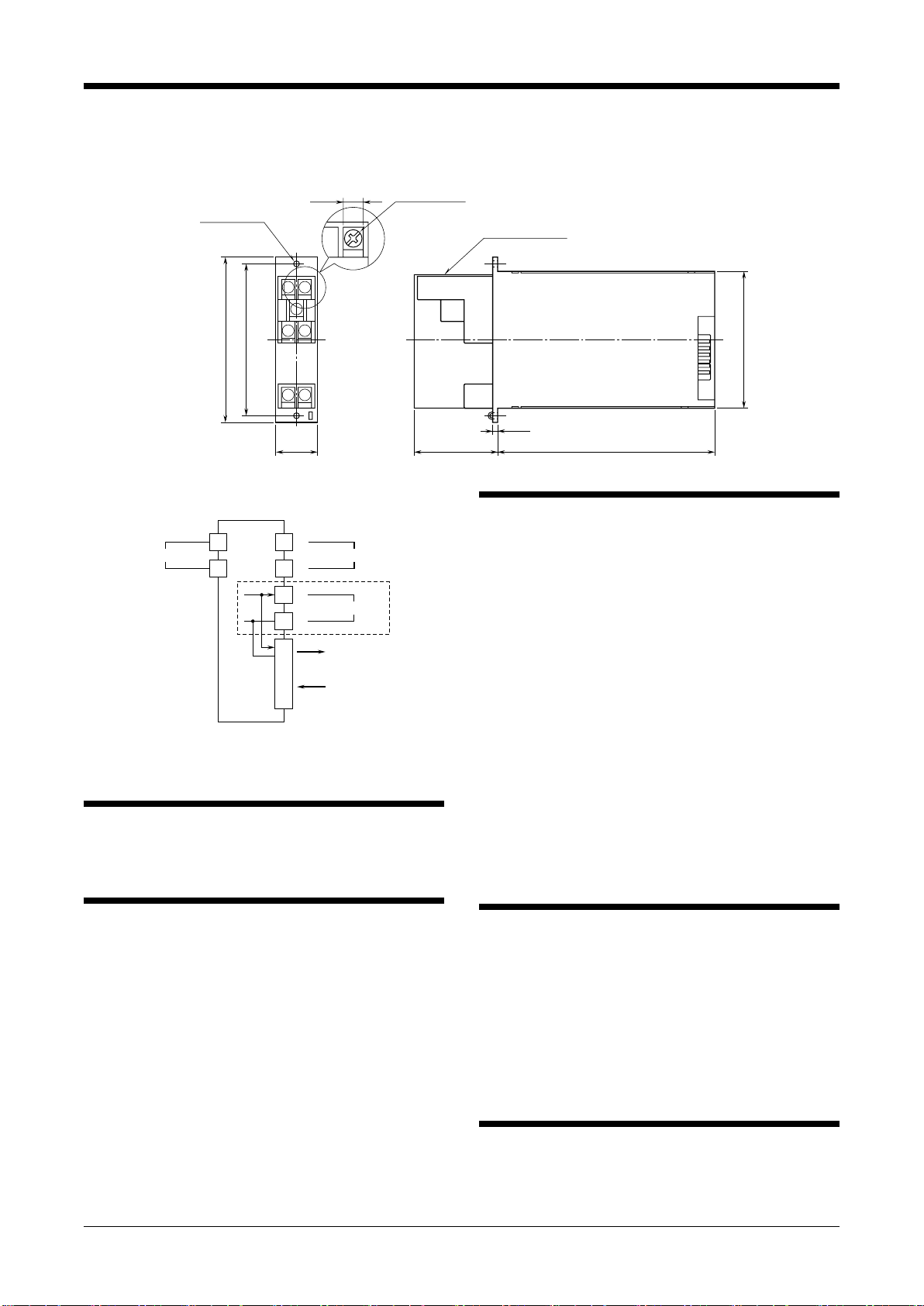
■EXTERNAL DIMENSIONS unit: mm (inch)
130 (5.12)
3 (.12)
51 (2.01)
82 (3.23)
2–4.3 (.17) dia.
MTG HOLE
TERMINAL COVER
7–M3.5 SCREW
8 (.31)
91 (3.58)
99 (3.90 )
25 (.98)
12
3
56
78
■CONNECTION DIAGRAM
INPUT
+
–
1
OUTPUT 1
2
7
8
+
–
OUTPUT 2
5
6
CONNECTOR
OUTPUT 2*
POWER
*For 1 output channel type, OUTPUT 1 is also connected to the
card-edge connector inside.
Note: The section enclosed by broken line is only for 2nd output channel.
WIRING INSTRUCTIONS
■SCREW TERMINAL
Torque: 0.8 N·m
CHECKING
1) Terminal wiring: Check that all cables are correctly con-
nected according to the connection diagram.
2) Power input voltage: Check voltage supplied to the rack
(model: 10BXx). For the DC power source, be sure that
the ripple level is within 10% p-p.
3) Input: Check that the input signal is within 0 – 100% of
the full-scale.
4) Output: Check that the load resistance meets the de-
scribed specifications.
ADJUSTMENT PROCEDURE
This unit is calibrated at the factory to meet the ordered
specifications, therefore you usually do not need any cali-
bration.
For matching the signal to a receiving instrument or in case
of regular calibration, adjust the output as explained in the
following.
■HOW TO CALIBRATE THE OUTPUT SIGNAL
Use a signal source and measuring instruments of sufficient
accuracy level. Turn the power supply on and warm up for
more than 10 minutes.
1) ZERO: Apply 0% input and adjust output to 0%.
2) SPAN: Apply 100% input and adjust output to 100%.
3) Check ZERO adjustment again with 0% input.
4) When ZERO value is changed, repeat the above proce-
dure 1) – 3).
5) Go through the same procedure for Output 2. Extender
Card (model: 10EC) is required to access the Output 2
Adjustments on top of the unit maintaining electrical
connection at the rear connector.
MAINTENANCE
Regular calibration procedure is explained below:
■CALIBRATION
Warm up the unit for at least 10 minutes. Apply 0%, 25%,
50%, 75% and 100% input signal. Check that the output
signal for the respective input signal remains within accu-
racy described in the data sheet. When the output is out of
tolerance, recalibrate the unit according to the “ADJUST-
MENT PROCEDURE” explained earlier.
LIGHTNING SURGE PROTECTION
We offer a series of lightning surge protector for protec-
tion against induced lightning surges. Please contact us to
choose appropriate models.
10 AC
EM-0836 Rev.7 P. 2 / 2
MG CO., LTD. www.mgco.jp
5-2-55 Minamitsumori, Nishinari-ku, Osaka 557-0063 JAPAN


