Bytronic BY11600 User manual

© Bytronic srl.
Via Como, 55 - 21050 Cairate (VA) - Tel. 0331/312523 - Fax. 0331/313077 - WEB: www.bytronic.it - email: bytronic@bytronic.it
Unauthorized reproduction and even partial distribution is prohibited
BY11600_M2_V1_EN 1.1
BY11600
Differential relay type B
(BY11600_M2_V1)
AFTER INSTALLATION, MANDATORY PROCEDURE MUST BE PERFORMED IN
CHAPTER 9 !
This documentation is the exclusive property of:
Bytronic Srl - Via Como 55 - 21050 Cairate (VA) - ITALY.
It cannot be copied, modified or distributed, even partially, in any way and by any means, except with the
explicit consent of the Owner.
The information and technical data contained in this documentation are subject to Copyright and intended
exclusively and exclusively for Persons and / or Companies to whom they are expressly granted with
restrictions on use.
Bytronic reserves the right to modify the specifications given without notice, at any time, according to the
evolution of materials, technologies and production needs.
Bytronic is not responsible in any way for the consequences caused by the lawful or illegal use of the content
of this document, whether due to inaccuracies, errors, incorrect interpretations or other.
No responsibility can be attributed to Bytronic Srl regarding any possible damage to things or persons
deriving from any use of the described equipment. Its suitability, field of application and type of installation
must be assessed by the user, who is obliged to comply with all the safety regulations in force and adopt
all suitable solutions to avoid any damage deriving from the use of the equipment, assuming it total
responsibility.

© Bytronic srl.
Via Como, 55 - 21050 Cairate (VA) - Tel. 0331/312523 - Fax. 0331/313077 - WEB: www.bytronic.it - email: bytronic@bytronic.it
Unauthorized reproduction and even partial distribution is prohibited
BY11600_M2_V1_EN 1.2
WARNING!
It is mandatory to have the product installed by a
qualified electrician, according to the safety
regulations in force.
This product is intended to be installed inside a switchboard or protection box, protected from
external agents, chemicals and vapors.
All the prescriptions and specifications provided in this manual must be respected.
Under no circumstances should the electrical, thermal and / or mechanical limits indicated be
exceeded, respectively the provisions for installation, use and maintenance.
Refer to the 'Technical data' and the information in the various chapters.
It is forbidden for any reason to open the casing of the product and / or its accessories.
Under no circumstances should you attempt to repair or modify the product and / or
accessories.
In the event of a breakdown, repair is only permitted at the factory when possible.
Do not install or replace the product or accessories that present damage to the casing.
Any operation on the electrical contacts of the product must be performed in the absolute
absence of voltage.
Disconnect voltage before opening the panel and starting any operation.
Periodically subject the product to TEST with the appropriate button, on a monthly basis.
Periodically, it is advisable to check visually that the casing of the product and accessories are
intact and not compromised, for example, by any over-temperatures that may have been
generated inside the switchboard or by the wiring due to high currents.
The transparent front should only be cleaned with a soft cloth and, if necessary, with water-
based detergent.
Never use solvents, alcohol or abrasive cloths.
The product is NOT suitable for use in explosive areas and in any case in the presence of
flammable substances even if occasionally or accidentally present.
Do not dispose of this product together with other unsorted solid waste.
It must be disposed of in accordance with the regulations for the recycling of electronic
components.
Failure to comply with these provisions relieves Bytronic Srl of any liability and causes the forfeiture
of any form of guarantee.

© Bytronic srl.
Via Como, 55 - 21050 Cairate (VA) - Tel. 0331/312523 - Fax. 0331/313077 - WEB: www.bytronic.it - email: bytronic@bytronic.it
Unauthorized reproduction and even partial distribution is prohibited
BY11600_M2_V1_EN 1.3
SUMMARY
1REFERENCES........................................................................................................................................................1.4
2GENERALITY ........................................................................................................................................................2.1
3CONNECTIONS AND SYSTEM REQUIREMENTS.....................................................................................................3.2
3.1 GENERAL SCHEME ..................................................................................................................................................... 3.2
3.2 CHOICE OF DETECTION DEVICE (TORB).......................................................................................................................... 3.3
3.3 PLANTING REQUIREMENTS .......................................................................................................................................... 3.3
3.3.1 Short circuit and overload protection.......................................................................................................... 3.3
3.3.2 Auxiliary power protection .......................................................................................................................... 3.3
3.3.3 Connection and positioning of the detection device ................................................................................... 3.3
3.3.4 Passage of conductors in the detection device............................................................................................ 3.6
3.3.5 Processing device positioning (MRCD) ........................................................................................................ 3.7
3.3.6 Connections to MRCD terminals (general) .................................................................................................. 3.7
3.3.7 Connection of the Failure output................................................................................................................. 3.7
3.3.8 Connection of the Alarm output.................................................................................................................. 3.7
3.3.9 Connection of the Reset input remotely ...................................................................................................... 3.8
3.3.10Use of the Data Port.................................................................................................................................... 3.8
4PRINCIPLE OF OPERATION...................................................................................................................................4.1
5OPERATION.........................................................................................................................................................5.1
5.1 FRONT PANEL ........................................................................................................................................................... 5.2
5.2 MEASUREMENT PAGE DISPLAY..................................................................................................................................... 5.3
5.2.1 High Resolution Measurements (only in Instant mode, 0.03A) ................................................................... 5.4
6OPERATING CONDITIONS ....................................................................................................................................6.1
6.1 GENERALITY ............................................................................................................................................................. 6.1
6.2 ALARM CONDITIONS .................................................................................................................................................. 6.1
6.2.1 Alarm condition storage (Memo Alarm = On) ............................................................................................. 6.3
6.3 FAULT CONDITIONS.................................................................................................................................................... 6.4
6.3.1 Intervention times ....................................................................................................................................... 6.5
6.4 TEST EXECUTION ....................................................................................................................................................... 6.6
6.4.1 Effect of the Test on the Alarm output ........................................................................................................ 6.7
6.5 RESET ..................................................................................................................................................................... 6.7
7OPERATION OF THE UP AND DOWN BUTTONS....................................................................................................7.1
7.1 'UP' BUTTON FUNCTIONS............................................................................................................................................ 7.1
7.1.1 Selection of the tripping differential current (I
n)........................................................................................ 7.1
7.1.2 Access to programming of operating parameters ...................................................................................... 7.1
7.1.3 Regulation functions in programming the operating parameters .............................................................. 7.1
7.1.4 Execution of the 'CT recognition procedure'................................................................................................ 7.1
7.2 FUNCTIONS OF THE 'DOWN' KEY ................................................................................................................................. 7.2
7.2.1 Selection of downtime (
t).......................................................................................................................... 7.2
7.2.2 Regulation functions in programming the operating parameters .............................................................. 7.2
8OPERATING PARAMETERS...................................................................................................................................8.1
8.1 LIST OF OPERATING PARAMETERS.................................................................................................................................. 8.3
9CT RECOGNITION PROCEDURE ............................................................................................................................9.1
10 RESIDUAL CURRENT MONITORING DURING INSTALLATION OR TESTING ..........................................................10.1
11 TECHNICAL DATA ..............................................................................................................................................11.1

© Bytronic srl.
Via Como, 55 - 21050 Cairate (VA) - Tel. 0331/312523 - Fax. 0331/313077 - WEB: www.bytronic.it - email: bytronic@bytronic.it
Unauthorized reproduction and even partial distribution is prohibited
BY11600_M2_V1_EN 1.4
1REFERENCES
This manual is in the following update state:
•File name:………………………….. Manual BY11600_M2_EN_08.docx
•Revision:………………………………… 08
•Date:………………………………………… 18.02.2021
The content refers to the firmware version 02.01.01 and later.
THE IMAGES CONTAINED IN THIS DOCUMENTATION ARE FOR APPROXIMATE
PURPOSE AND COULD BE DIFFERENT FROM THE REAL ONES.

© Bytronic srl.
Via Como, 55 - 21050 Cairate (VA) - Tel. 0331/312523 - Fax. 0331/313077 - WEB: www.bytronic.it - email: bytronic@bytronic.it
Unauthorized reproduction and even partial distribution is prohibited
BY11600_M2_V1_EN 2.1
2Generality
The BY11600 is a separate type B differential current protection (and monitoring) device (MRCD), according to
Annex M of the European standard CEI EN 60947-2: 2019-03, identical to the international standard IEC 60947-2:
2016 -06 / COR1: 2016-11.
It is built in a sealable container for 3-module DIN 46277 (EN 50022) bar, with protection of the adjustments by
means of a transparent door, with access to the 2 operating buttons (Test and Reset) with a special tool.
It is classified as MRCD with voltage source, at a nominal voltage of 230 Vac 50/60 Hz.
It can function both as a non-delayed and delayed device, according to the requirements of the standard.
It is designed for control on a three-phase network at 400V 50/60 Hz but also single-phase, and can operate for
frequencies greater than 400Hz (up to a maximum of 1kHz).
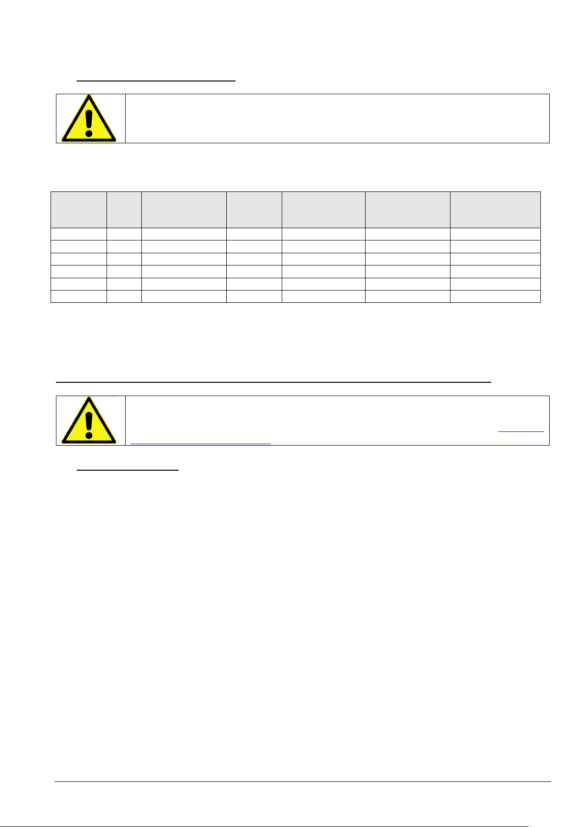
It uses a separate Bytronic detection device (Current Transformer, CT) of the TORB series, to be chosen based on
the use of 6 models, with an internal diameter between 35 and 210mm.
The BY11600 is able to recognize which detection device it is connected to, thanks to the "CT recognition
procedure”, Described in detail below.
Overall, the BY11600 has 8 step current settings (0.03, 0.1, 0.3, 0.5, 1, 3, 5 and 10A), one of which is instantaneous
(0.03A) and the other 7 delayed, with 9 step-adjustable non-operation times (0.1, 0.2, 0.3, 0.4, 0.5, 0.75, 1, 5 and
10 s).
Based on the CT used, only the current flows that it is able to manage are made available.
For any selected current flow rate, tripping is guaranteed for a sinusoidal differential current of more than 10
times at the rated frequency and 20 times direct current, keeping the non-tripping time when in the delayed
mode.
The BY11600 has 2 relay outputs of 230V 10A AC1 as standard, one with a 'fault' for controlling suitable
interruption devices or for monitoring intervention, and the other with 'alarm', fully programmable by the user,
for example to monitor residual current of 6mA.
It also has a 128x128 pixel high contrast 'ink look' graphic display, on which the settings and measurements are
shown in detail, as well as the operating states and alarm / fault conditions.
During normal operation, all the information relating to the measurements (Irms, Iac and Idc), adjustments of the
Failure output and type of detection device are collected on the single measurement page that is always visible.
No button action is required to view other information. The possibility of testing or restoring is also reported. In
case of intervention, the display page automatically changes to show its diagnostic data. Upon reset, the main
page reappears. All this, after installation, allows you to use the instrument even after a long time without the aid
of the instruction manual.
The particular technology with which the BY11600 was created makes it practically immune to magnetic fields
external to the detection device (e.g. terrestrial magnetic field) and also does not require any degaussing
procedure for the CT. In addition, the devices of the TORB series are practically insensitive to temperature
variations within the expected operating range.
The alarm / fault conditions indicated on the display are also indicated by the 2 LEDs with which it is equipped,
one red with high brightness (Fault) and one green for the indication of ON and alarm.
It is also possible to perform the 'Reset' remotely on a standard opto-isolated input.
By using the BY11800 add-on module, the BY11600 can be monitored remotely on a high-speed opto-isolated
RS485 network, with MODBUS RTU or ASCII MODBUS protocol with automatic recognition.
More details in the following sections.

© Bytronic srl.
Via Como, 55 - 21050 Cairate (VA) - Tel. 0331/312523 - Fax. 0331/313077 - WEB: www.bytronic.it - email: bytronic@bytronic.it
Unauthorized reproduction and even partial distribution is prohibited
BY11600_M2_V1_EN 3.2
3Connections and system requirements
3.1 General scheme
1 2 3 4 5 6 7 8 9
10 11 12 13 14 15 16 17
Vmains (Un)
Failure
Alarm
Reset
Remote
Uc = 150 - 260
Vac / dc
Vaux (Us)
Load
TORB xxx
Data port
2x1A fuses
Device of
overload
protection /
short circuit
Breaker

© Bytronic srl.
Via Como, 55 - 21050 Cairate (VA) - Tel. 0331/312523 - Fax. 0331/313077 - WEB: www.bytronic.it - email: bytronic@bytronic.it
Unauthorized reproduction and even partial distribution is prohibited
BY11600_M2_V1_EN 3.3
3.2 Choice of detection device (TORB)
The detection device must NECESSARILY be of Bytronic manufacture and belong to the "TORBxxx" family.
Bytronic declines any responsibility deriving from the use of non-original devices.
The number represented after the prefix "TORB" represents the internal diameter of the hole for the passage of the cables.
The limits of use of the various devices are summarized in the table:
Template
In(A)
Operating limit
Imax (A)
Inno = 6 In
(A)
Max
section/phase
mmq (3F + N)
Minimum
Threshold In(A)
Maximum
Threshold In (A)
TORB 35
60
170
360
16
0,03
3
TORB 60
75
200
450
25
0,03
3
TORB 80
140
330
840
70
0,03
3
TORB 110
200
450
1200
100
0,1(1)
5
TORB 160
275
600
1650
150
0,3(1)(2)
10
TORB 210
350
720
2100
2x185
0,3(1)(2)
10
Table 1: Choice of detection device
Note (1): The 0.03A range is not available when combining this model.
Note (2): The minimum selectable range is 0.1A but, only at this range, the measurement error is not guaranteed (can be
greater, max. +/- 10%).
Use a sensing device having an internal diameter at least double the diameter of the cable or cable bundle.
All models can withstand the overload regime determined by the non-tripping limit current (Inno), in the
absence of a differential current I. However,in order to guarantee intervention in all conditions in the
presence of I, the following system prescriptions must be respected, especially for the 'Passage of
conductors in the detection device' (3.3.4).
3.3 Planting requirements
3.3.1 Short circuit and overload protection
An upstream protection device against overloads and short-circuit currents must be provided upstream.
The protection device must have a breaking capacity at least equal to the short circuit current presumed at the point of
installation.
3.3.2 Auxiliary power protection
The connection of the auxiliary power supply (Us) must take place via 1A protection fuses.
3.3.3 Connection and positioning of the detection device
The type of connection of the detection device is all the more important as:
•the currents to be detected are low and for which it is required to intervene and / or
•the installation environment is hostile, due to the presence of strong radio frequency electromagnetic fields (e.g.
repeaters, radio links, transmitters, etc.) or due to the presence in the system of elements which are in turn
disturbing elements such as inverters, phase cutting, tripping of remote control switches etc. etc., and / or
•the connection distance between the detection device and the MRCD is long
Clearly it would be desirable that ALL precautions be taken to avoid untimely interventions, which can cause significant
economic losses due to the unnecessary detachment of the load (system restart, stop important processes, etc ...).

© Bytronic srl.
Via Como, 55 - 21050 Cairate (VA) - Tel. 0331/312523 - Fax. 0331/313077 - WEB: www.bytronic.it - email: bytronic@bytronic.it
Unauthorized reproduction and even partial distribution is prohibited
BY11600_M2_V1_EN 3.4
However, adopting all the precautions beforehand even where objectively it is not necessary, means facing higher plant costs
which in small plants can be significant.
It is therefore advisable to follow an 'increasing guarantees' scheme, establishing what is necessary according to the Table 2
and gradually taking more targeted (and expensive) measures if problems arise with the system built.
Basic condition
Twisted cable
Shielded cable with EMC
hook
Additional EMC devices
Radio frequency EM fields
-
• (always)
[1]
Passage of strong impulse
currents in the switchboard
/ load
-
• (always)
[1]
Use for In= 0.03A
-
• (always)
[2]
In≥ 0.1A, distance <50cm
• (allowed)
• (optional)
-
In≥ 0.1A, distance between
50cm and 3mt
-
• (always)
[2]
In≥ 0.1A, distance between
3 and 10mt (maximum)
-
• (always)
[3]
Table 2: Choice of the type of basic connection to the detection device
Note [1]: The device is optional and when present, its nature is studied on a case by case basis
Note [2]: The device is strongly recommended and in any case when present, its nature is studied on a case by case basis
Note [3]: The device is mandatory and its nature is studied on a case-by-case basis
Regardless of the type of connection made, the following precautions must ALWAYS be taken:
1. The sensor wiring must be SEPARATED from the other wiring in the panel (it must not be
'bundled' or put in the same sheaths with power, power or control cables).
2. The wiring must follow a path as far as possible away from cables and power devices
3. The CT MUST be installed as far as possible from power and control devices (remote switches,
electromagnets, inverters, transformers, drives, permanent magnets, etc., etc. ..).
Being by its nature and operation a device sensitive to both continuous and alternating magnetic
fields, it is absolutely necessary to avoid that it can 'receive' electromagnetic signals from nearby
devices.

© Bytronic srl.
Via Como, 55 - 21050 Cairate (VA) - Tel. 0331/312523 - Fax. 0331/313077 - WEB: www.bytronic.it - email: bytronic@bytronic.it
Unauthorized reproduction and even partial distribution is prohibited
BY11600_M2_V1_EN 3.5
In detail, the types of connection and the recommended methods are as follows:
TYPE OF CONNECTION /
ADDITIONAL DEVICE
DESCRIPTION
Twisted cable.
2 standard electric wires, at least 0.5 sq. Mm in section, which must be carefully
intertwined (twisting) with each other.
It is not suitable for currents <0.1A and for distances greater than 50cm.
It is the most economical solution but it exposes to untimely tripping risks in the
presence of EMC disturbances.
Shielded cable with EMC fixing.
The maximum recommended length for connection with the detection device is
3m.
This is the solution to always adopt when you can.
Connections over 3mt for differential currents <0.1A (0.03A) are always STRONGLY
RECOMMENDED. The risk of untimely interventions, despite the precautions and
precautions, are almost inevitable.
We always recommend good quality cable, for example type BELDEN 9841 or
equivalent cable (available on request). The shielding must be connected to the DIN
bar (which in turn must be connected to the switchboard and to the earth) but ONLY
near the connection terminals of the BY11600 (not at other points), using special
metal clamps. Do not connect the shield in other ways (e.g. with welded wire).
There are solutions for the "fast" connection of the shielding to the DIN bar, such as
this type of hook:
This hook (for BELDEN 9841 cable or equivalent) is also available on request.
Additional EMC devices
ALWAYS apply for connections> 3mt.
They can be of various kinds, and consist of elements such as ferrites or special
shielded cables with reinforced shielding, also in combination with each other.
Their use in particular cases may also be necessary for connections of less than 3m
in length, in particularly hostile environmental conditions. The appropriate
application of these devices requires the intervention of our Technical Assistance
service, because they are highly dependent on the type of system and specific
environmental conditions.
Regardless of the type of cables used, the connection on the detection device must take place with 6.3mm Female Faston,
to be crimped on each of the 2 conductors and to be inserted indifferently (without polarity) in the TORBxxx contacts.
When using shielded cable:
•DO NOT connect the shield near the TORB detection device (isolate it), e
•From the BY11600 side, the 2 wires to be inserted in the respective terminals must be stripped (7mm).

© Bytronic srl.
Via Como, 55 - 21050 Cairate (VA) - Tel. 0331/312523 - Fax. 0331/313077 - WEB: www.bytronic.it - email: bytronic@bytronic.it
Unauthorized reproduction and even partial distribution is prohibited
BY11600_M2_V1_EN 3.6
3.3.4 Passage of conductors in the detection device
The following requirements must be observed:
•Use a detection device having an internal diameter (d2) at least double the diameter of the cable or cable bundle
(d1), and in any case in accordance with the Table 1;
•Keep the conductors together, as close as possible to the center of the sensing device. A conductor closer than
the others to the edge of the cable passage can determine the saturation of the ferromagnetic core with
consequent non-linear, incorrect or even absent response;
•To help adequately protect the detection device from any mechanical damage due to the repulsive effect of the
conductors as a result of any short-circuit currents (single-phase) not intercepted in time by the short-circuit
protection device, mechanically block the cable bundle immediately upstream and downstream (e.g. with clamps,
tapes or high-resistance clamps). The lock must be able to withstand a force F in Newton of at least:
Where is it:
Icc is the effective value of the presumed short-circuit current at the CT, in Ampere;
Lis the distance between the upstream and downstream blockages in meters;
dis the distance between the conductors in meters;
depending on the type of system and the direction and phase of the currents in each conductor.
•The bundle of cables that passes through the detection device must not have bends at a distance of less than 2 times
the diameter in both directions;
•In extremely critical cases, install a ferromagnetic sleeve arranged around the conductors inside the detection device
with diameter D = internal diameter and length L = 2D, to make uniform the distribution of the magnetic field,
avoiding untimely intervention by high inrush currents ;
•The detection device must be crossed in the same direction by all the active conductors of the line, including the
neutral (when present). The neutral must NOT be earthed downstream of the detection device;
•In the event that the protected power line has a metal armature that must be earthed, this must NOT cross the CT.
If it is grounded and crosses the CT, it must be passed back to the CT to cancel any fault current that may travel
through it.
TA
TA

© Bytronic srl.
Via Como, 55 - 21050 Cairate (VA) - Tel. 0331/312523 - Fax. 0331/313077 - WEB: www.bytronic.it - email: bytronic@bytronic.it
Unauthorized reproduction and even partial distribution is prohibited
BY11600_M2_V1_EN 3.7
3.3.5 Processing device positioning (MRCD)
The BY11600 (MRCD) must be installed on DIN 46277 rail (omega bar), POSSIBLY at a distance ≥ 50mm from other equipment
or modules installed nearby, which could interfere electromagnetically.
This prescription becomes mandatory for precautionary purposes if, if not respected, anomalies of measurement or
apparently unwanted interventions occur.
3.3.6 Connections to MRCD terminals (general)
The terminals of the MRCD accept cables with a maximum section of 2.5mm2 and have a maximum current capacity of 10 A.
The maximum (recommended) stripping length of the cable is 7mm and the maximum tightening torque is 0.5 nm
3.3.7 Connection of the Failure output
In the event that the MRCD is used as a protective device:
1. ONLY the "Fault" output can and must properly control a suitable disconnecting device
(disconnector);
2. The "Fault" output cannot be used directly as an interruption device
The BY11600 is able to control both 'current launch' and 'undervoltage' release devices, because the “Fault” output can be
programmed NO or NC at rest and the presence of the changeover contact makes it flexible use.
When using the MRCD at the current value In= 0.03 A, it becomes a NON delayed type and it must be
combined with a cut-off device of an appropriate size for the system, whose overall opening time is less
than 0.015 s, in order to guarantee compliance with the intervention according to Table B.1 of the
Standard.
Otherwise, when the MRCD is delayed, a convenient switch / contactor can be used, according to the overall intervention
time desired (maximum MRCD intervention time declared + intervention time of the chosen device; see 'Technical features').
The section of the connection cables with the release device must be suitable with respect to its absorption, and in any case
between 1 and 2.5mm2.
3.3.8 Connection of the Alarm output
It can be used flexibly according to its programming, for diagnostic, warning or secondary purposes ("monitor").
The "Alarm" output MUST NOT BE USED FOR PROTECTION.
It MUST NOT COMMAND THE INTERRUPTION DEVICE.
It has the same electrical characteristics as the Failure output and also the same prescriptions as regards the connection to a
load.

© Bytronic srl.
Via Como, 55 - 21050 Cairate (VA) - Tel. 0331/312523 - Fax. 0331/313077 - WEB: www.bytronic.it - email: bytronic@bytronic.it
Unauthorized reproduction and even partial distribution is prohibited
BY11600_M2_V1_EN 3.8
3.3.9 Connection of the Reset input remotely
The MRCD has an optoisolated input which when powered with a voltage between 150 and 260 V indifferently ac or dc,
performs the same function as the 'Reset' button on the front of the instrument.
There are no particular recommendations regarding this link.
3.3.10Use of the Data Port
The data port is used for remote monitoring of the device.
It must be connected to the 1 DIN module for serial communications BY11800, isolated at 3kV, which allows the status and
measurements of the BY11600 to be put on the MODBUS network (RTU or ASCII), in order to monitor a system with multiple
protected areas.
Through MODBUS communication, for each BY11600 + BY11800 connected to the network, it is possible to know:
•Device data (version-revision)
•The type of TORB sensor connected
•The settings (programming)
•Operating conditions (Sensitivity and delay)
•The measurements of the current RMS, AC and DC components, expressed in%
•The Alarm and Fault states, with type (exceeding I, sensor fault, Test etc ..) and intervention values%
The connection and operation details are contained in the BY11800 product documentation.
DO NOT CONNECT ANY DEVICE OTHER THAN BY11800 TO THE DATA PORT.

© Bytronic srl.
Via Como, 55 - 21050 Cairate (VA) - Tel. 0331/312523 - Fax. 0331/313077 - WEB: www.bytronic.it - email: bytronic@bytronic.it
Unauthorized reproduction and even partial distribution is prohibited
BY11600_M2_V1_EN 4.1
4Principle of operation
The instrument is a type B differential relay delayed and instantaneous with separate detection device, which meets the
specifications of the Standard CEI EN 60947-2: 2019-03 Annex M.
It has a sensitivity of differential currentnadjustable in steps between 30mA and 10A, divided as follows:
0.03 - 0.1 - 0.3 - 0.5 - 1 - 3 - 5 and 10A.
In this documentation, when we speak of "current measurement", it is always intended as DIFFERENTIAL current (I).
The 0.03 A rating classifies the instrument as suitable for additional protection from direct contacts, i.e. without delay and
with intervention times in accordance with Table B.1 of the Standard, provided it is used with a suitable detection device (see
Table 1)with equally suitable interruption device suitably connected to the 'Fault' output.
The other current flows classify it as a delayed type device suitable for protection from indirect contacts, giving the possibility
to adjust the non-operation timetin steps from a minimum of 0.1 to a maximum of 10 s, divided as follows:
0.1 -0.2 -0.3 - 0.4 - 0.5 -0.75 - 1 - 5 and 10 s
This is the time within which the MRCD DEFINITELY DOES NOT intervene in the presence of a DOUBLE current with respect
to the selected one (2 In).
The instrument is suitable for fire protection in TT TN systems, by regulating In <= 0.3A for the terminal circuits, and <=
1A for the distribution circuits (IEC 60364-4-482).
Normally the instrument is supplied from the factory already coupled to a “TORBxxx” type detection device chosen by the
customer when ordering.
The instrument is in fact able to recognize the type of sensor connected and in order to use it with a different type sensor
(different diameter) it is always necessary to use an auto-recognition procedure that can be performed in the field. Without
carrying out the procedure, the instrument will go into Fault indicating the anomaly.
The procedure is also necessary by replacing the sensor with one of the same type, to calibrate any small construction
differences that could cause excessive measurement errors.
Current measurements are performed in true RMS (TRMS) and also in separate components (ac and dc).

© Bytronic srl.
Via Como, 55 - 21050 Cairate (VA) - Tel. 0331/312523 - Fax. 0331/313077 - WEB: www.bytronic.it - email: bytronic@bytronic.it
Unauthorized reproduction and even partial distribution is prohibited
BY11600_M2_V1_EN 4.2
The intervention thresholds of the MRCD are 6, to which the 2 relay outputs correspond respectively:
•“Fault” threshold (rms, ac and dc) e
•"Alarm" threshold (rms ac and dc)
The one to be used for protection is the "Fault" output.
It is only partially programmable, compared to the Alarm one which is totally programmable but can only be used for
reporting purposes and NEVER for protection. The differences are as follows:
Programmable function
"Fault" output
"Alarm" output
Relay contact polarity
YES (NOT C)
YES (NOT C)
Current threshold (rms)
NO (0.85 In)
YES (0 - 2 In, 0 = Excluded)
Current threshold (ac)
NO (0.75 In)
YES (0 - 2 In, 0 = Excluded)
Current threshold (dc)
NO (1.5 In)
YES (0 - 2 In, 0 = Excluded)
Intervention delay for rms, ac and
dc thresholds
NO in the non-delayed (INST)
mode,
YES by selection t in the delayed
mode
YES (0 -10.0 s)
Threshold intervention
memorization
NO (always memorized)
YES (ON - OFF)
When we speak of "threshold", that of "Fault" will always be implied, unless specified as "Alarm".
In conditions of differential current in PURE sinusoidal regime, the BY11600 non-intervention threshold is 0.75Infor the
alternating component.
For the PURA continuous component, on the other hand, it is 1.5In.
If both the ac and dc components are present, the non-intervention threshold is set at 0.85Inof the rms component.
In order to intervene, the differential current must remain above the rms, ac or dc component beyond any set non-operation
time if in the delayed mode, otherwise immediately in the instantaneous mode.
The first of the valid conditions will trigger the Fault relay.
The "Fault" condition cannot be restored until the differential current returns below all the intervention thresholds. Until
this happens, the 'Reset' button and the relative 'Remote reset' input remain inactive.

© Bytronic srl.
Via Como, 55 - 21050 Cairate (VA) - Tel. 0331/312523 - Fax. 0331/313077 - WEB: www.bytronic.it - email: bytronic@bytronic.it
Unauthorized reproduction and even partial distribution is prohibited
BY11600_M2_V1_EN 5.1
5operation
After correctly connecting the instrument as shown in the diagram, it is also necessary to check that it is correctly configured
before powering the protected system, namely:
•The connected detection device (TA) must be the one with the diameter foreseen and previously recognized. If the CT has
also been replaced in the system with one of the same type, the 'CT recognition procedure' described in the relevant chapter.
•The value of Inand of t must be those desired. Set them as described in the chapter 'Operation of the UP and DOWN
buttons'.
•The polarity of the output relays must be the desired one. To see 'Operating parameters'.
•The behavior of the Alarm output (if used) must be set as desired. To see 'Operating parameters'.
When the system is running, to carry out the Test, press the Test button (corresponding to the letter T in the negative on the
display) and then see operation in the section 'Test execution'.
For explanations regarding the alarm conditions, fault conditions and their recovery, see the relative chapters 'Alarm
conditions', 'Fault conditions' is 'Reset'.
After installation and correct programming, the key protection door can be leaded through the adjacent side holes of the
container. The functions of Test is Reset they will however be accessible by suitable means.

© Bytronic srl.
Via Como, 55 - 21050 Cairate (VA) - Tel. 0331/312523 - Fax. 0331/313077 - WEB: www.bytronic.it - email: bytronic@bytronic.it
Unauthorized reproduction and even partial distribution is prohibited
BY11600_M2_V1_EN 5.2
5.1 Front panel
ON / ALARM led
ON FIXED = Indicates normal operating status
ON FLASHING = Indicates Alarm relay output in ALARM status.
To see 'Alarm conditions'.
FAULT LED
When lit steadily, the Fault relay output is in a FAULT state.
To see 'Fault conditions'.
TEST button
It is accessible from the front of the instrument with the door closed, using a suitable tool
(pen, screwdriver, etc.). See operation in section 'Test execution'.
RESET button
It is accessible from the front of the instrument with the door closed, using a suitable tool
(pen, screwdriver, etc.). See operation in section 'Reset'.
'UP' button
It is accessible only with the door open.
To see 'Functions of the UP button.
'DOWN' button
It is accessible only with the door open.
To see 'Functions of the DOWN key'.
Graphic display
View measures, states and messages.
The one represented is the page of 'logo' displayed at power on, which disappears after 3 s.
The indications displayed will be explained later.
1
2
3
4
5
6
7
3
4
5
6
1
2
7

© Bytronic srl.
Via Como, 55 - 21050 Cairate (VA) - Tel. 0331/312523 - Fax. 0331/313077 - WEB: www.bytronic.it - email: bytronic@bytronic.it
Unauthorized reproduction and even partial distribution is prohibited
BY11600_M2_V1_EN 5.3
5.2 Measurement page Display
The instrument, when it is in its standard operating mode, has a single measurement display page:
The displayed one is the page as per factory settings, in the absence of differential current.
The RMS measurement of the current and its AC component alternates approximately every 3 seconds:
The 'INFO' bar contains the type of detection device associated on the left and firmware version information on the right.
CAUTION: this is the setting for protection against indirect and additional contact against direct contact (In= 0.03A). This
setting is NOT POSSIBLE if TORB 110, TORB 160 or TORB 210 are used (the instrument does not admit 0.03 A selection).
In case of use with TORB 110, TORB 160 or TORB 210 the first factory page will be the following (ex. TORB 160):
Remember also that with TORB160 and 210 it is possible to select the 0.1A range but there could be a greater measurement
error of the DC component, which in any case does not exceed +/- 10%.
The "T" at the top right indicates that the "Test" button is enabled and that if pressed it will trigger the "Failure" output.
In the central part of the status bar, the information of the polarity (+) NC, with positive safety, of the Failure output can be
present:
When the instrument is set up for protection against indirect contact (In= 0.03 A) no delay can be set.
Delay t is adjustable only if In> 0.03 A
3 s
Value In
Valuet
Measure RMS
and AC
components
DC component
measurement
Test available
INFO bar

© Bytronic srl.
Via Como, 55 - 21050 Cairate (VA) - Tel. 0331/312523 - Fax. 0331/313077 - WEB: www.bytronic.it - email: bytronic@bytronic.it
Unauthorized reproduction and even partial distribution is prohibited
BY11600_M2_V1_EN 5.4
An icon may appear in the display area between the two measurements, such as:
Pre-failure condition
(flashing icon - flashing value)
The continuous component threshold has been exceeded
(the value on the display flashes) but we are within the
non-operation time (10 s). If the condition remains
beyond 10 s, the "Fault" intervention will take place. For
more details, see 'Fault conditions'.
If only the AC or RMS threshold is exceeded, the
alternation of the display stops in favor of the value that
is exceeding the threshold, keeping it displayed.
Pre-alarm and alarm condition
(flashing icon - flashing value)
By default the alarm conditions are deactivated and this
signal does not appear.
When it appears, it means that an appropriate alarm level
has been programmed which causes, in addition to the
flashing of the icon and the value concerned, also the
flashing (delayed) of the green ON / Alarm LED. The
"Alarm" output is active only with a flashing green LED.
For all the details, see 'Alarm conditions'.
5.2.1 High Resolution Measurements (only in Instant mode, 0.03A)
It is possible, for diagnostic purposes such as the monitoring of residual direct currents, to activate the display of the
measurements in 'High resolution' when the instrument is set for protection against indirect contact. This allows you to view
the current values with a decimal but on the other hand the 'roll' that derives from it in the presence of small perturbations
of the currents, could annoy you. For this reason the factory is set to 'Off'. To see 'Operating parameters'.
Flashing Fault
Icon
Flashing value
Flashing alarm
icon
Flashing
value
Values with 1
decimal

© Bytronic srl.
Via Como, 55 - 21050 Cairate (VA) - Tel. 0331/312523 - Fax. 0331/313077 - WEB: www.bytronic.it - email: bytronic@bytronic.it
Unauthorized reproduction and even partial distribution is prohibited
BY11600_M2_V1_EN 6.1
6Operating conditions
6.1 Generality
Since the instrument is powered, it is IMMEDIATELY operational, regardless of what is shown on the display. The conditions
that are the source of "Fault" (exceeding current thresholds, anomalies of the detection device) are monitored and processed
immediately, in accordance with point M.8.3.4.3.
After the instrument has been commissioned, no verification or calibration procedure is required each time it is switched on.
The factory "Alarm" conditions are deactivated. If you want to use them, they must be properly set. Once set, they become
operational symmetrically under the "Fault" conditions.
6.2 Alarm conditions
THE ALARM CONDITIONS, AND CONSEQUENTLY THE ALARM OUTPUT, CANNOT BE USED FOR
PROTECTION BUT ONLY FOR MONITORING, SIGNALING OR SECONDARY FUNCTIONS.
Unlike the Fault conditions which depend on the instantaneous values of the measurements, the Alarm conditions depend
on the indications on the display and on the arbitrarily set delay time.
The measured values shown on the display represent the average values measured by the instrument and therefore are
delayed with respect to the instantaneous values. The thresholds possibly set on these values cannot therefore be used for
any reason as protection against indirect contacts nor as additional protection against direct contacts.
The alarm conditions can be set (or excluded) individually for the RMS value, for the AC component and for the DC
component. The first of the conditions that is satisfied causes the relay to intervene, in the mode chosen with the other
parameters.

© Bytronic srl.
Via Como, 55 - 21050 Cairate (VA) - Tel. 0331/312523 - Fax. 0331/313077 - WEB: www.bytronic.it - email: bytronic@bytronic.it
Unauthorized reproduction and even partial distribution is prohibited
BY11600_M2_V1_EN 6.2
The parameters that concern the setting of the alarm conditions are:
•HiResDispI
•PolarAlarm
•ThRMS Alarm
•ThAC Alarm
•ThDC Alarm
•tRMS Alarm
•tAC Alarm
•tDC Alarm
•Memo Alarm
The meaning of each parameter is described in the section 'List of operating parameters'
Exceeding one or more alarm thresholds (rms, ac and / or dc) is indicated by the flashing alarm icon on the display among
the three measurements, with the value(s) concerned flashing.
In the example it is assumed that the alarm threshold value of the alternating component (ThAC Alarm) has been set at a
level lower than 66% with respect to the value of In.
The alternation of the AC / RMS measurement on the viewing of the AC value, the one that is exceeding the threshold is
blocked).
The flashing of the icon and the value indicate the instantaneous exceeding of the threshold (pre-alarm condition) but not
the intervention of the "Alarm" output, which occurs only when the relative delay time runs out (in the example, after the
eventual time oftAC Alarm if set).
The "Alarm" output is active only when the green ON / Alarm LED flashes.
Flashing alarm
icon
Flashing
value
Table of contents
Popular Control Unit manuals by other brands

Watts
Watts LFM115-74 Installation operation & maintenance

Saftronics
Saftronics DG2 PLUS Series manual

Panasonic
Panasonic CF-BAW0512U operating instructions

Beckhoff
Beckhoff EPI2 Series Documentation

Hansen
Hansen HS6 Specifications, Applications, Service Instructions & Parts

Atag
Atag MCBA1417 instructions