BZB Gear BG-VOP-MT User manual

BG-VOP-MT
HDMI2.0 over IP Multicast Transceiver System
with Video Wall support & PoE support
User Manual
Made in Taiwan

TABLE OF CONTENTS
INTRODUCTION.....................................................................................................................1
FEATURES..............................................................................................................................1
PACKAGE CONTENTS ..........................................................................................................2
CONNECTION DIAGRAM ......................................................................................................2
SPECIFICATIONS...................................................................................................................3
PANEL DESCRIPTIONS.........................................................................................................4
IR PASS-THROUGH...............................................................................................................6
WARRANTY............................................................................................................................7
MISSION STATEMENT...........................................................................................................8

-1-
INTRODUCTION
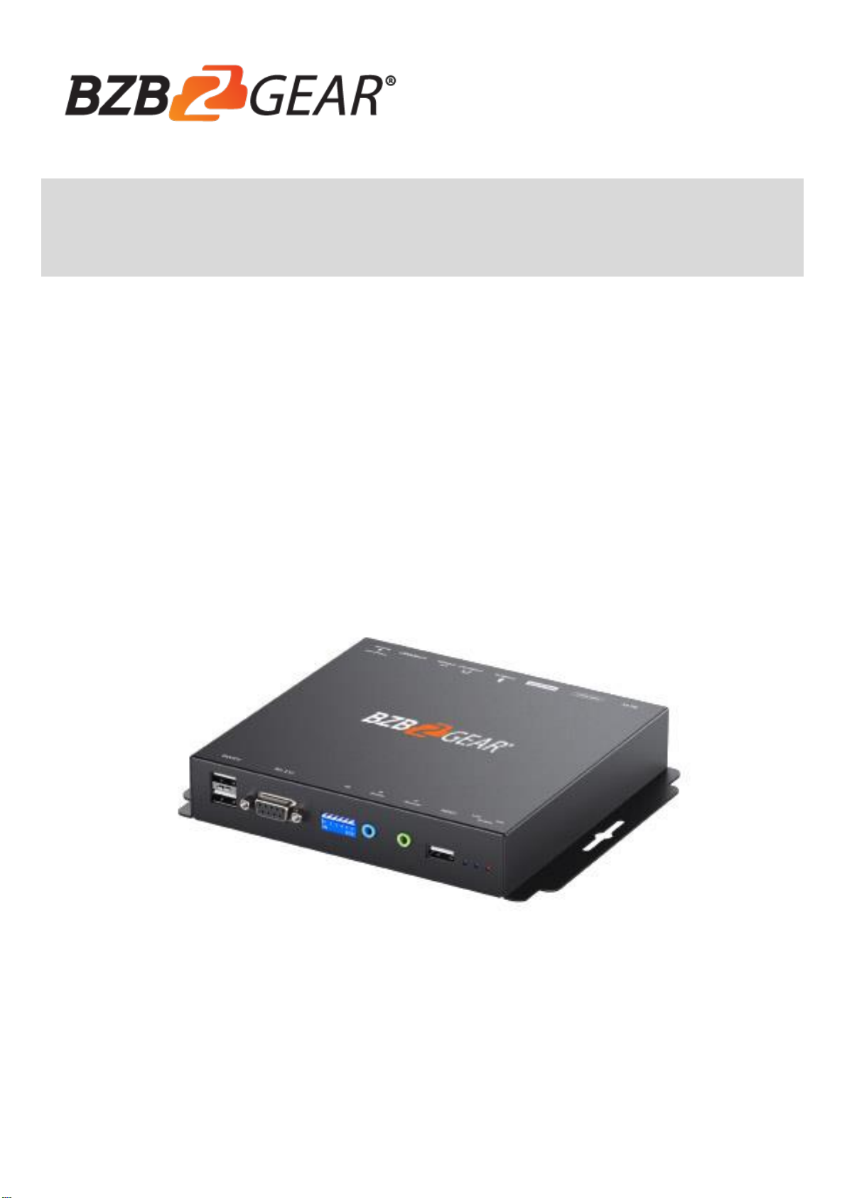
The BG-VOP-MT HDMI 2.0 over IP Multicast Transceiver System with Video Wall support & PoE
support boosts your audio/video transmission distance up to 120m (396ft) in UHD 4K2K format. With
cost-effective ethernet cable users can readily extend UHD sources from DVD players, Blu-ray Disc players,
gaming consoles, PCs, and any other HDMI source to any HDMI display. In addition, BG-VOP-MT is HDCP
compliant, and supports PoE, IR, and RS-232 pass-through.
By transmitting the A/V signal over the local area network the BG-VOP-MT makes it easy to add a
source or display to your system anywhere there is an active ethernet connection. When combined with
broadcasting management software and Gigabit Ethernet network switch (supporting IGMP), BG-VOP-MT
is a complete UHD video broadcasting solution for digital signage. The transmitting format can be Point
to Point, Point to Many, or Multi-Cast. Multi-casting requires a Managed Gigabit Ethernet Switch with
802.1Q VLAN function to allow multiple video sources. To provide more flexibility for installations, BG-
VOP-MT can work as either a transmitter or a receiver.
FEATURES
Supports HDMI input up to 4K2K@60 4:4:4 8bits
Supports HDMI output up to 4K2K@30 RGB
Supports High Dynamic Range (HDR)*
HDMI 2.0a compliant
HDCP 2.2 compliant
Supports PoE function
Can be configured as a transmitter or receiver
Flexible and scalable UHD Video Broadcasting by Gigabit Ethernet LAN/Switch
One to one, one to many & multi-casting broadcasting architecture
Each transmitter can be theoretically multicast up to an unlimited number of displays in video wall
applications or unlimited displays in multicast applications
Supports full frequency IR signal from 20KHz to 60KHz
Bi-directional IR path
Full Duplex RS-232 control up to 115,200 bps
Up to 1,023 Groups Multi-Casting
Easy Dip Switch matching for multi-casting group configuration
Latency: 1080p60Hz: 23ms
Supports Video Wall function
Supports 180 and 270 clockwise image rotation
Supports USB2.0
Wall mounting housing design for easy and robust installation
○
!
Due to the video compression, some distortion may occur in HDR mode.

-2-
PACKAGE CONTENTS
1x BG-VOP-MT
1x IR blaster cable
1x IR receiver cable
1x User Manual
CONNECTION DIAGRAM

-3-
SPECIFICATIONS
Model Name
BG-VOP-MT
Technical
BG-VOP-MT
Role of usage
Transmitter
HDMI compliance
HDMI
HDCP compliance
Yes
Input Video support
Up to 4K2K@60 (4:4:4 8bits)
Output Video support
Up to 4K2K@30 (RGB)
Latency
2 frames (33 ms) maximum
HDMI over UTP
transmission [24-bit]
Ultra HD (4K2K60)-120m (396ft) [CAT.X]
Audio support
Surround sound (up to 7.1ch) or stereo digital audio
Input TMDS signal
1.2 Volts [peak-to-peak]
Input DDC signal
5 Volts [peak-to-peak, TTL]
ESD protection
Human body model —±15kV [air-gap discharge] & ±8kV [contact discharge]
IR pass-thru
Full-duplex bi-directional
RS-232 support
Yes
I/O connector
2x HDMI + 4x 3.5mm + 3x USB + 1x RJ45 + 1x DIN9
HDMI source control
Controllable via IR pass-through from RX to TX and from TX to RX with IR extenders
IR remote control
Electro-optical characteristics: = 25° / Carrier frequency: 20-60kHz
HDMI connector
Type A [19-pin female]
Min DIN connector
DIN-9
RJ45 connector
WE/SS 8P8C with 2 LED indicators
3.5mm connector
IR blaster & IR receiver
Mechanical
Housing
Metal enclosure
Dimensions
[L x W x H]
Model
180 x 142 x 28mm[7" x 5.5" x 3.2"]
Package
264 x 170 x 77mm[10.3" x 6.7" x 3"]
Carton
430 x 358 x 291mm[1'4" x 1'2" x 11.5"]
Weight
Model
664g [23 oz]
Package
889g [2 lbs]
Fixedness
Wall-mounting case with screws
Power supply
5V 2A DC / 48V POE
Power consumption
7.5 Watts [max]
Operation temperature
0~40°C [32~104°F]
Storage temperature
-20~60°C [-4~140°F]
Relative humidity
20~90% RH [no condensation]

-4-
PANEL DESCRIPTIONS
1. USB(USB 2.0 downstream port): Connect to USB flash driver or other USB devices
(device configure as RX)
2. RS-232: Connect to PC serial port with a DB-9 male-male cable
3. Dip Switch: Video channel selection
4. IR Blaster: Infrared 3.5mm socket for plugging in the extension cable of IR blaster
5. IR Receiver: Infrared 3.5mm socket for plugging in the extension cable of IR receiver
6. USB: Connect to upstream USB host (device configure as TX)
7. Link LED indicator:
[Blink] When unit connect a Cat-5/5e/6 cable
[Shine] When transmitting unit connect to a HDMI source and linked to the receiving unit
8. System LED indicator:
[Blink] When unit is connected with a power supply unit
[Solid] Device is ready
9. Info LED indicator: When user clicks the LED button in the software, the LED light will blink 30 seconds.
10. +5V DC: Connect to 5V DC power supply
11. HDMI IN: Connects to a HDMI source with a HDMI cable
12. HDMI OUT: Connects to a HDMI display with a HDMI cable.
13. Analog audio line in: Connect to upstream audio output (device configured as TX)
14. Analog audio line out: Connect to downstream headphone output (device configured as RX)
15. Micro-USB: for F/W update
16. RJ-45: Gigabit Ethernet port
17. Dip Switch: configures as a transmitter or receiver
[] configures as a transmitter

-5-
[] configures as a receiver
Notes: TX/RX group ID dip-switch setting
1. For ID=1~63, please refer the table below to set up (Hardware control)
2. For ID=64~1023, please adjust the DIP switch to ID=0, and the real ID can be decided by the
external software (Software control)
ID
Pin1
Pin2
Pin3
Pin4
Pin5
Pin6
ID
Pin1
Pin2
Pin3
Pin4
Pin5
Pin6
0
↑
↑
↑
↑
↑
↑
32
↑
↑
↑
↑
↑
↓
1
↓
↑
↑
↑
↑
↑
33
↓
↑
↑
↑
↑
↓
2
↑
↓
↑
↑
↑
↑
34
↑
↓
↑
↑
↑
↓
3
↓
↓
↑
↑
↑
↑
35
↓
↓
↑
↑
↑
↓
4
↑
↑
↓
↑
↑
↑
36
↑
↑
↓
↑
↑
↓
5
↓
↑
↓
↑
↑
↑
37
↓
↑
↓
↑
↑
↓
6
↑
↓
↓
↑
↑
↑
38
↑
↓
↓
↑
↑
↓
7
↓
↓
↓
↑
↑
↑
39
↓
↓
↓
↑
↑
↓
8
↑
↑
↑
↓
↑
↑
40
↑
↑
↑
↓
↑
↓
9
↓
↑
↑
↓
↑
↑
41
↓
↑
↑
↓
↑
↓
10
↑
↓
↑
↓
↑
↑
42
↑
↓
↑
↓
↑
↓
11
↓
↓
↑
↓
↑
↑
43
↓
↓
↑
↓
↑
↓
12
↑
↑
↓
↓
↑
↑
44
↑
↑
↓
↓
↑
↓
13
↓
↑
↓
↓
↑
↑
45
↓
↑
↓
↓
↑
↓
14
↑
↓
↓
↓
↑
↑
46
↑
↓
↓
↓
↑
↓
15
↓
↓
↓
↓
↑
↑
47
↓
↓
↓
↓
↑
↓
16
↑
↑
↑
↑
↓
↑
48
↑
↑
↑
↑
↓
↓
17
↓
↑
↑
↑
↓
↑
49
↓
↑
↑
↑
↓
↓
18
↑
↓
↑
↑
↓
↑
50
↑
↓
↑
↑
↓
↓
19
↓
↓
↑
↑
↓
↑
51
↓
↓
↑
↑
↓
↓
20
↑
↑
↓
↑
↓
↑
52
↑
↑
↓
↑
↓
↓
21
↓
↑
↓
↑
↓
↑
53
↓
↑
↓
↑
↓
↓
22
↑
↓
↓
↑
↓
↑
54
↑
↓
↓
↑
↓
↓
23
↓
↓
↓
↑
↓
↑
55
↓
↓
↓
↑
↓
↓
24
↑
↑
↑
↓
↓
↑
56
↑
↑
↑
↓
↓
↓
25
↓
↑
↑
↓
↓
↑
57
↓
↑
↑
↓
↓
↓
26
↑
↓
↑
↓
↓
↑
58
↑
↓
↑
↓
↓
↓
27
↓
↓
↑
↓
↓
↑
59
↓
↓
↑
↓
↓
↓
28
↑
↑
↓
↓
↓
↑
60
↑
↑
↓
↓
↓
↓
29
↓
↑
↓
↓
↓
↑
61
↓
↑
↓
↓
↓
↓
30
↑
↓
↓
↓
↓
↑
62
↑
↓
↓
↓
↓
↓
31
↓
↓
↓
↓
↓
↑
63
↓
↓
↓
↓
↓
↓

-6-
IR PASS-THROUGH
[IR Extenders]
IR Blaster
IR Receiver
[IR Sockets]
IR BLASTER: plug in the IR blaster to emit all IR command signals received from the IR receiver for device control.
IR RECEIVER: plug in the IR receiver to receive all IR command signals from the remote control of the corresponding
devices.
[Definition of IR Earphone Jack]
IR Blaster
IR Receiver
Incorrect placement of IR Blaster and Receiver may result in the failure of the
IR extenders. Please check carefully before plugging in the IR extender to the
respective IR sockets. Warranty will not cover the damage.
CAUTION!

-7-
WARRANTY
BZBGEAR wants to assure you peace of mind. We're so confident in the quality of our products that
along with the manufacturer's one-year limited warranty, we are offering free second-year warranty
coverage upon registration*.
Taking advantage of this program is simple, just follow the steps below:
1. Register your product within 90 days of purchase by visiting BZBGEAR.com/warranty.
2. Complete the registration form. Provide all necessary proof of purchase details, including serial
number and a copy of your sales receipt.
For questions, please call 1.888.499.9906 or email support@bzbgear.com.
For complete warranty information, please visit BZBGEAR.com/warranty or scan the QR code below.
*Terms and conditions apply. Registration is required.

-8-
MISSION STATEMENT
BZBGEAR manifests from the competitive nature of the audiovisual industry to innovate while
keeping the customer in mind. AV solutions can cost a pretty penny, and new technology only adds to it.
We believe everyone deserves to see, hear, and feel the advancements made in today’s AV world
without having to break the bank. BZBGEAR is the solution for small to medium-sized applications
requiring the latest professional products in AV.
We live in a DIY era where resources are abundant on the internet. With that in mind, our team
offers system design consultation and expert tech support seven days a week for the products in our
BZBGEAR catalog. You’ll notice comparably lower prices with BZBGEAR solutions, but the quality of the
products is on par with the top brands in the industry. The unparalleled support from our team is our
way of showing we care for every one of our customers. Whether you’re an integrator, home theater
enthusiast, or a do-it-yourselfer, BZBGEAR offers the solutions to allow you to focus on your project and
not your budget.
Table of contents
Other BZB Gear Transceiver manuals
Popular Transceiver manuals by other brands

REXON
REXON PJ2-COM RADIO Operator's manual

Kenwood
Kenwood ProTalk TK-3401D Quick reference guide

NXP Semiconductors
NXP Semiconductors freescale semiconductor MC13211 Reference manual

Nat
Nat SM05 Installation and operation manual

ELECRAFT
ELECRAFT K3 installation instructions

Eddystone
Eddystone Orion 5700 Series Installation notes