General Maintenance & Troubleshooting Guide
Thank you for purchasing one of our high quality products. Proper application, installation and maintenance of this
product will result in many years of satisfactory service. Please read the instructions below completely before installing
your new unit.
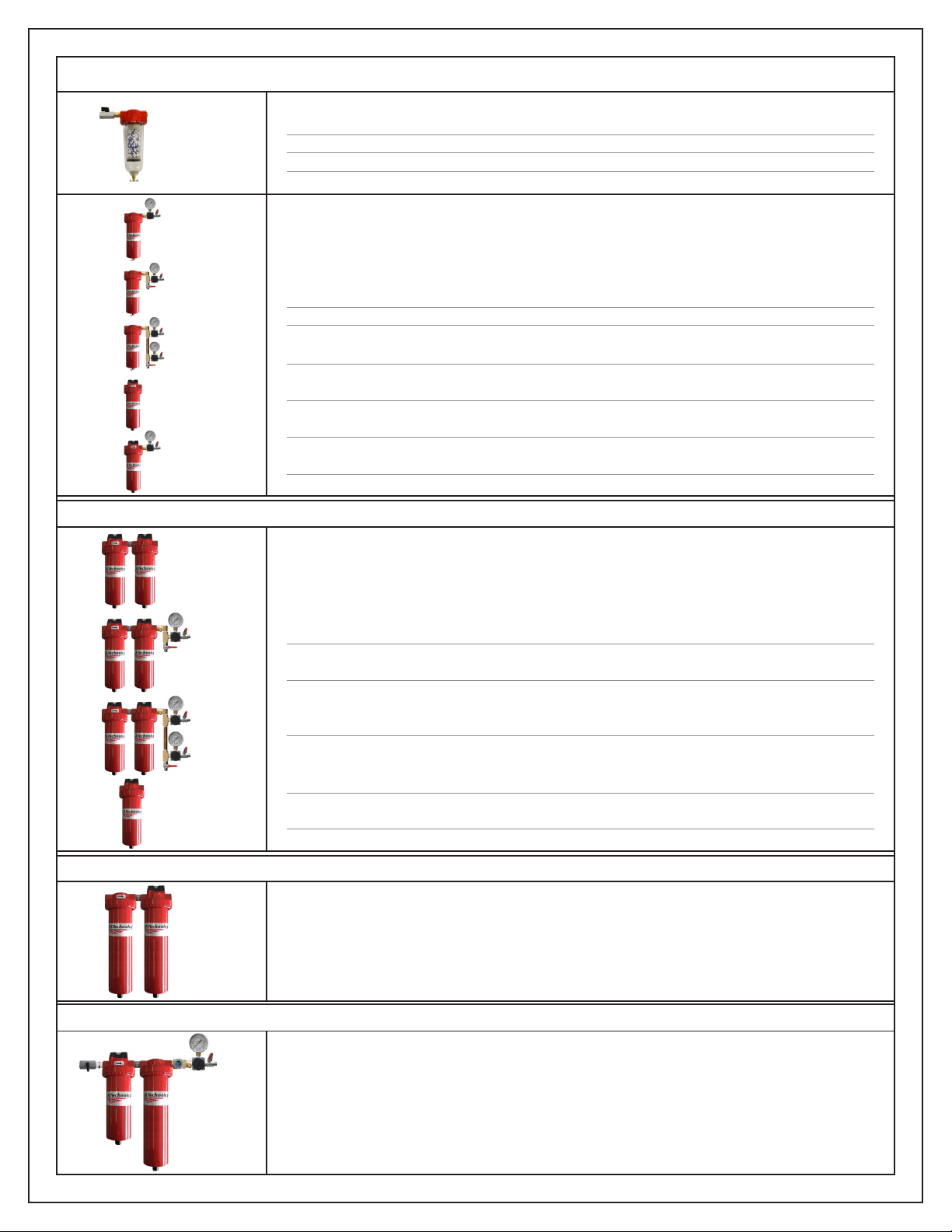
Maximum Pressure: 150 PSIG for all units with clear poly carbonate bowls and/or differential pressure indicators. 200 PSIG for metal bowl units WITHOUT different pressure indicators. 500 PSIG for
designated high pressure, black units.
Maximum Temperature: 125°F. For higher temperature applications, contact the manufacturer.
Except as specified by the manufacturer, this product is specifically designed for compressed air service (excluding life support applications). Use with any other fluid (liquid or gas) or in life support
applications is a misapplication. Manufacturer’s warranty is void in the event of a misapplication and the manufacturer assumes no responsibility for any resulting loss. Before using for any fluid or life
support application, consult the manufacturer for approval.
For use with polycarbonate bowl and different pressure indicators:
DO NOT place units with polycarbonate bowls into service without the metal bowl guard installed. If the unit is in service without the metal bowl guard in place, the manufacturer’s warranty is void and the
manufacturer assumes no responsibility for any resulting loss.
Certain chemicals, compressor oils, solvents, household cleaners, paints, etc. will attack polycarbonate and case cracking/crazing. Bowls and indicators should be inspected periodically and replaced if
necessary. For information on materials which are harmful to polycarbonate, contact Mobay Chemicals or General Electric. Do not use indicators with systems that use synthetic compressor oils.
Installation instructions:
1. Install unit as close as possible to the point-of-use. The cooler the air entering the filter, the more efficient the water/oil removal. For
maximum efficiency, air inlet temperature should be 40-70°F. DO NOT ALLOW UNIT TO FREEZE!
2. Avoid using fittings that will restrict air flow. Generally, the port size of the unit should be the same size or larger than the pipe size.
3. Install the unit in vertical position with the drain pointing down. Automatic drains have 1/8” NPT threaded ports for attachment of a
drain hose to channel the condensate to a collection point. If using a drain hose, use as short a hose as possible and ensure
hose is not crimped or otherwise restrict the flow of the condensate.
4. Ensure air flow through the unit is in the direction of the arrow on the indicator and/or head. WARNING: AIR FLOW IN OPPOSITE OF
THE ARROW COULD DAMAGE THE ELEMENTAND/OR AUTOMATIC DRAIN.
5. Units with 1-1/4” ports and larger are shipped without the drain installed. Install the drain using a 1/2” pipe nipple provided prior to
pressurizing the air system.
6. Units with flange ports are shipped without the differential pressure indicator installed. Install the indicator prior to pressurizing the
air system.
7. When installing oil removal filters, purge all downstream lines of oil prior to installation of the unit.
Service instructions:
1. For units with manual drains, open drain at lest daily. Sever water problems may require more frequent draining.
2. Replace filter elements every 6-12 months, depending on use. To replace:
a) Isolate unit and depressurize or depressurize the air system.
b) Remove bowl assembly by hand or for flange units, remove bolts at base of unit.
c) Unscrew/remove the element (for flange unit, remove pin securing filter media and pull out filter media)
d) Install new element by tightening by hand to a snug fit. DO NOT OVERTIGHTEN.
e) Clean bowl assembly and inspect polycarbonate bowls for cracks, crazing and replace if needed. To clean bowl, rinse with
water and wipe clean. CAUTION: DO NOT TWIST FLOAT ASSEMBLY. DAMAGED TO ASSEMBLY WILL RESULT AND DRAIN WILL
NOT FUNCTION PROPERLY.
f) Replace the bowl assembly and ensure it is securely installed.
g) Repressurize the system.
Air leaks from indicator Indicator/seals dam aged by chem ical
attack or UV ex posure Replace indicator assem bly
Indicator shows RE D with no air flowing
through the unit Defective indicator Call factory and replace indicator assem bly
Clogged filter elem ent Replace the filter elem ent
Air flow exceeds capacity of unit Install a higher capacity unit
Float assem bly bent/dam aged Replace drain assem bly
Sedim ent clogged drain
Rem ove float assem bly and clean bowl and
drain (DO NO T U SE S OLV E NTS )- Contact
the factory for drain instructions
Float A ssem bly bent/dam aged Replace drain assem bly
Sedim ent clogged drain
Rem ove float assem bly and clean bowl and
drain (DO NO T U SE S OLV E NTS )- Contact
the factory for drain instructions
Air bubble trapped in drain housing
(external drains only)
Open petcock or bleeder valve on top of
drain to relieve air bubble
Contam ination from downstream piping Replace downstream air lines or install a
filter at the end of the line
In s uffic ie nt le ve l of filtra tio n In s tall a tig hter filte r in -lin e
Elem ent saturated with contam ination Replace the filter elem ent
W ater vapor condensing after filter Air entering filter is warm er than the air
downstream - cool the air prior to the filter
Elem ent saturated with contam ination Replace the filter elem ent
Air lines not purged of oil prior to
ins talla tion
Replace downstream air lines or purge lines
of oil
In s uffic ie nt le ve l of filtra tio n In s tall a tig hter filte r in -lin e
Elem ent saturated with contam ination Replace the filter elem ent
A ir leaks from drain
Indicator shows RED with air flowing
through the unit
Oil downstream of filter
W ater downstream of filter
Particulate downstream of filter
Drain will not discharge