5
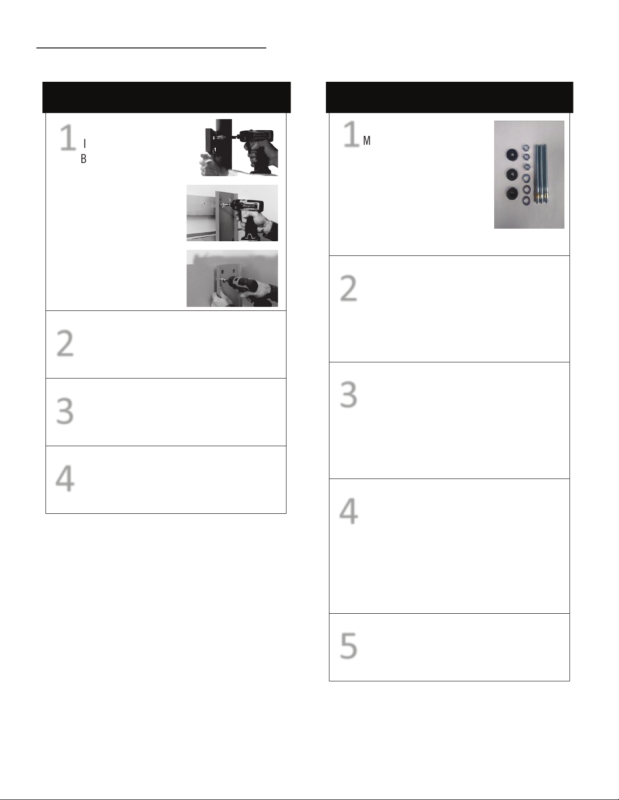
INLET AND DISCHARGE PIPING
!CAUTION: Do not operate unit without inlet-air filtration�
If the air is dirty, pipe the filter to a source of clean air�
Do not install piping with a diameter lower than that of the pump
intake�
!CAUTION: Do not use PVC plastic in the discharge line�
Use hand-welded or threaded steel or copper pipes and cast-iron
fittings that are safe for the discharge pressure and temperature�
ELECTRICAL
!WARNING: Compressor installation must be performed
by a qualified electrician in accordance with the National
Electrical Code (NEC) or the Canadian Electrical Code
(CEC), the National Electrical Safety Code (NESC) OSHA
code, and/or any local or state codes having precedence�
Be sure of proper wire sizing and that the circuit breaker and the
distance from the breaker is within suggested range� Confirm your
electrical-supply voltage matches what is required for the motor�
!WARNING: The compressor must be grounded� Ground-
ing reduces the risk of electric shock� Certain C-Aire
Models are equipped with a cord that has a grounding
wire with a grounding plug� The plug must be plugged
into an outlet that is installed and grounded in accor-
dance with all local codes and ordinances�
!WARNING: Improper installation of the grounding
plug will result in a risk of electric shock� When repair
or replacement of the cord or plug is required, do not
connect the grounding wire to either flat-blade terminal�
The insulated wire with a green outer surface and yellow
stripes is the grounding wire�
NOTE: The installation, electric motor, wiring, and all electrical
controls must be in accordance with NFPA 70-1996 National
Electric Code, National Electric Safety Code, and state and local
codes� Failure to abide by the national, state, and local codes may
result in physical harm and/or property damage�
!DANGER: High voltage may cause personal injury or
death� Disconnect and lockout/tagout, per OSHA reg-
ulation 1910�147, all electrical power supplies before
opening the electrical enclosure or servicing�
!DANGER: Never assume a compressor is safe to work on
if it is not operating� It could restart at any time� Always
disconnect/ lockout/tagout before servicing�
!CAUTION: Dry pipe sprinkler compressor must be wired
to a reliable power source to be compliant with AHJ�
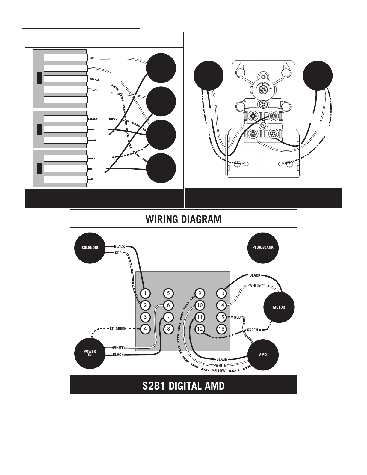
NOTE: Wiring diagrams for each model type are located on the
following page�
(ELECTRICAL CONTINUED ON NEXT PAGE)