C-Aire S244 User manual

REV. A
Dec/15/20
MODELS
Fire Protection Air Compressor
LL BP MANUAL
S244 S600


i
TABLE OF CONTENTS
SAFETY ��������������������������������������������������������������������������������������������������������������������������������������������������������������������������������������������������������������� 2
INSTALLATION ����������������������������������������������������������������������������������������������������������������������������������������������������������������������������������������������������� 2
ELECTRICAL�������������������������������������������������������������������������������������������������������������������������������������������������������������������������������������������������������� 4
START UP ������������������������������������������������������������������������������������������������������������������������������������������������������������������������������������������������������������ 5
DIGITAL AMD OPERATING INSTRUCTIONS ���������������������������������������������������������������������������������������������������������������������������������������������������������� 5
SYSTEM INSTALLATION DIAGRAMS��������������������������������������������������������������������������������������������������������������������������������������������������������������������� 7
MAINTENANCE���������������������������������������������������������������������������������������������������������������������������������������������������������������������������������������������������� 8
VALVES AND SWITCHES�������������������������������������������������������������������������������������������������������������������������������������������������������������������������������������� 8
S244 PARTS DIAGRAM���������������������������������������������������������������������������������������������������������������������������������������������������������������������������������������� 9
S600 PARTS DIAGRAM��������������������������������������������������������������������������������������������������������������������������������������������������������������������������������������10
TROUBLESHOOTING �����������������������������������������������������������������������������������������������������������������������������������������������������������������������������������������11
WARRANTY �������������������������������������������������������������������������������������������������������������������������������������������������������������������������������������������������������12
5. DIGITAL AMD
3. PUMP
2. AIR FILTER
4. DISCHARGE TUBE (S600)/HOSE (S244)
1. ELECTRICAL BOX
6. MOTOR
7. MANIFOLD 8. SOLENOID
9. CHECK VALVE
10. SAFETY RELIEF VALVE
11. BASE PLATE
(LOCATED BEHIND DIGITAL AMD)
Parts Identification

1
INTRODUCTION
The compressor you have purchased is a combination of nearly 100 different components, all of which have been carefully designed,
engineered, and assembled to ensure a long, dependable, trouble-free life� The product has been fully tested at the factory and has gone
through quality-control inspection prior to shipping�
Like any mechanical piece of equipment, it is necessary to fully understand the proper use of its operation and application�
Misuse of this valuable and helpful air-power source may shorten its expected life as well as void the warranty of the entire unit�
We ask you take the time to read this manual to ensure the dependable service you can expect from your C-Aire compressor�
Failure to do so can cause serious injury and may void all warranties�
Please take special notice of the safety precautions and safety information contained in this manual� Compressed air, like electricity,
is a very helpful and necessary tool� However, compressed air can be extremely dangerous and harmful when it is not understood or is
misused�
PRODUCT NUMBERING SYSTEM
Mount
P
244
600
280
281
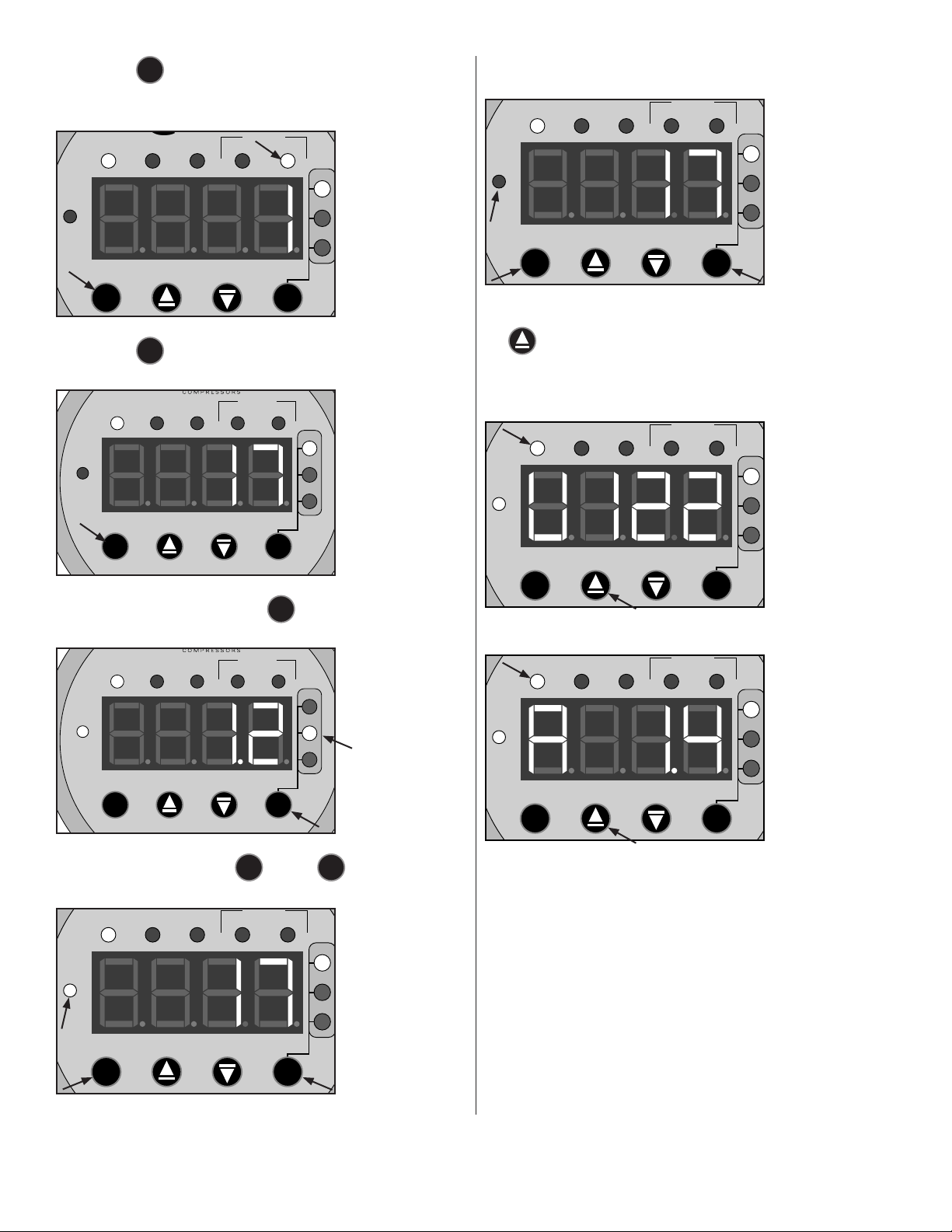
■SET PRESSURE IN SECONDS
■IDEAL FOR SINGLE VALVE SYSTEMS
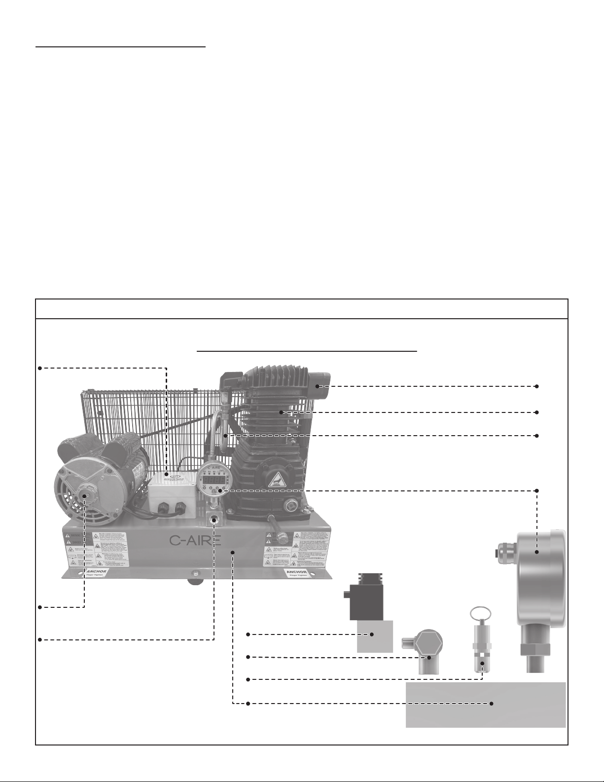
■INCLUDED:
• ANCHOR BOLTS
• POWER CORD (for installation and testing purposes)
!WARNING: Refer to the authority having jurisdiction
regarding hard wiring requirements�
■AVAILABLE ACCESSORIES
ACCESSORY PART NUMBER
FLOOR MOUNTING KIT INSTALL-S28
1/2” X 30” STAINLESS STEEL FLEXIBLE HOSE DT 3005 H / PACK OF 5: DT 3005 H-5PK
1/2” X 48” FLEXIBLE HOSE DT 4805 H / PACK OF 5: DT 4805 H-5PK
1/2” X 72” FLEXIBLE HOSE DT 7205 H / PACK OF 5: DT 7205 H-5PK
SYNTHETIC OIL LU E100 QT
Listings:
Pressure Switch: USA: UL 508 Canada: C22�2 No� 14
SPECIFICATIONS S244 S600
HP �5 1
SYSTEM CAPACITY
40 PSI 244 GALLONS 40 PSI 615 GALLONS
18 PSI 614 GALLONS 18 PSI 1510 GALLONS
10 PSI 1,188 GALLONS 10 PSI 2,962 GALLONS
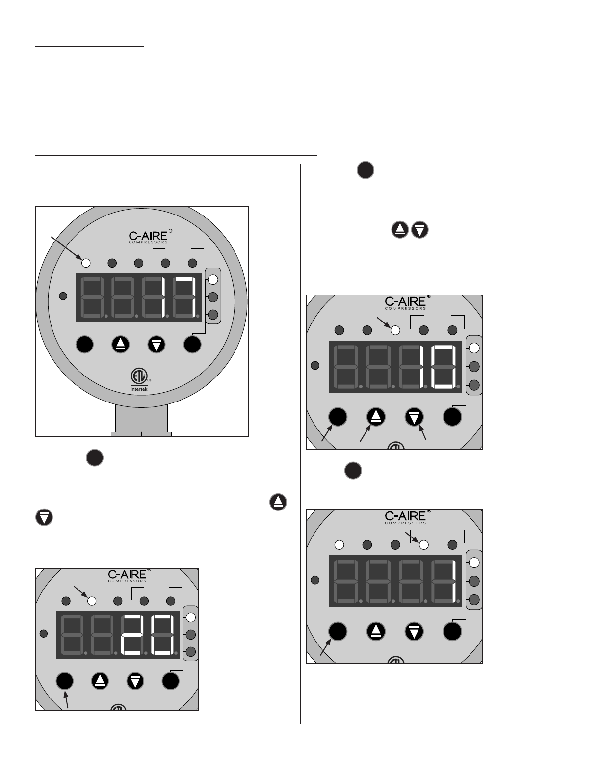
PRESSURE SWITCH
ADJUSTABLE: 5-55 PSI
FACTORY SET AT 10-20 PSI
MINIMUM DIFFERENTIAL: 5 PSI
MAXIMUM WORKING PRESSURE FOR UNIT: 40PSI
CFM 3�18 CFM @ 10 PSI 7�58 CFM @ 10 PSI
PUMP 1 CYLINDER, OIL LUBRICATED 2 CYLINDER, OIL LUBRICATED
CYLINDERS CAST IRON CAST IRON
VOLTS 115/230* 115/230*
PHASE 1 1
RUNNING AMPS 5�6 9�0
BREAKER SIZE 10 AMP RECOMMENDED 15 AMP RECOMMENDED
DIMENSIONS 28” X 14” X 18” 28” X 19” X 25”
WEIGHT 75�0 LBS 125�0 LBS
* These units should not be rewired to change between 115/230v� This is because the solenoid
is different and will not work properly on the other voltage

2
SAFETY
DEFINITIONS
!DANGER: Indicates a hazardous situation that, if not avoided, will result in death or serious injury�
!WARNING: Indicates a hazardous situation that, if not avoided, could result in death or serious injury�
!CAUTION: Indicates a situation that will or could cause minor injury or property damage�
GENERAL PRECAUTIONS
Read the Owner’s Manual before operating�
!DANGER:
Do not use compressed air for breathing air applications�
Beware of high voltage: disconnect lockout/tagout electric supply before servicing�
Ground compressor per codes�
!WARNING:
Beware of high-pressure air: do not bypass, modify, or remove safety/relief valves�
Beware of hot surfaces: allow unit to cool before servicing�
Do not operate with safety guards removed�
!CAUTION:
Never operate the compressor near flammable liquids or vapors�
Do not direct the air stream at body�
Drain tank air weekly to decrease risk of bursting�
NOTE: Per UL 1450:46�17 C-Aire recommends a maximum of 70% duty cycle for its compressors�
INSTALLATION
SELECTING A LOCATION:
C-Aire compressors are to be installed and operated in a clean, dry, well-lighted, and well-ventilated area�
Provide at least 200 cubic feet of fresh air per 1 hp�
Ideal operating temperatures are between 32°F and 100°F�
Avoid excessively humid areas, as moisture may form in the pump, producing sludge and causing moving parts to wear prematurely�
NOTE: The dry pipe/sprinkler system compressor is to be installed in accordance with the Standard for Installation of Sprinkler Systems,
NFPA 13�
!CAUTION: If temperatures consistently drop below 32° F, install the compressor in a heated area�
!CAUTION: Never operate the compressor in temperatures below 20°F or above 104°F�
!WARNING: A compressor should never be used in an area where toxic, corrosive, or volatile agents may be present�
(INSTALLATION CONTINUED ON NEXT PAGE)

3
MOUNTING THE COMPRESSOR
!CAUTION: Remove the compressor from the shipping packaging before mounting�
FLOOR MOUNTING
Mark hole loca�ons
Place unit in chosen loca�on,
mark 2 holes and remove
unit.
Floor Mount kits are included
and include 2 anchor bolts, nuts, washers,
and vibration absorption washers.
2 Drill holes
Drill 1.75” deep using a 3/8” masonry drill
bit in the floor at indicated markings.
3Install anchor bolts
Tap anchor bolts down to secure while
protec�ng bolt threads.
4
Secure Unit
Place unit on anchor bolts, slide on washer
and then loosely thread* nut over bolt.
* Do not �ghten nut. Tightening the nut may lead to
stress on the frame causing damage to the unit.
it.u
1
5 Install air filter assembly
INLET AND DISCHARGE PIPING
!CAUTION: Do not operate unit without inlet-air filtration�
If the air is dirty, pipe the filter to a source of clean air�
Do not install piping with a diameter lower than that of the pump intake�
!CAUTION: Do not use PVC plastic in the discharge line�
Use hand-welded or threaded steel or copper pipes and cast-iron fittings that are safe for the discharge pressure and temperature�

4
ELECTRICAL
!WARNING: Compressor installation must be performed by a qualified electrician in accordance with the National
Electrical Code (NEC) or the Canadian Electrical Code (CEC), the National Electrical Safety Code (NESC) OSHA code, and/or
any local or state codes having precedence�
Be sure of proper wire sizing and that the circuit breaker and the distance from the breaker is within suggested range� Confirm your
electrical-supply voltage matches what is required for the motor�
!WARNING: The compressor must be grounded� Grounding reduces the risk of electric shock� Certain C-Aire Models are
equipped with a cord that has a grounding wire with a grounding plug� The plug must be plugged into an outlet that is
installed and grounded in accordance with all local codes and ordinances�
!WARNING: Improper installation of the grounding plug will result in a risk of electric shock� When repair or replacement of
the cord or plug is required, do not connect the grounding wire to either flat-blade terminal� The insulated wire with a green
outer surface and yellow stripes is the grounding wire�
NOTE: The installation, electric motor, wiring, and all electrical controls must be in accordance with NFPA 70-1996 National Electric
Code, National Electric Safety Code, and state and local codes� Failure to abide by the national, state, and local codes may result in
physical harm and/or property damage�
!WARNING: These units should not be rewired to change between 115/230v� This is because the solenoid is different and
will not work properly on the other voltage
!DANGER: High voltage may cause personal injury or death� Disconnect and lockout/tagout, per OSHA regulation 1910�147,
all electrical power supplies before opening the electrical enclosure or servicing�
!DANGER: Never assume a compressor is safe to work on if it is not operating� It could restart at any time� Always
disconnect/ lockout/tagout before servicing�
!CAUTION: Dry pipe sprinkler compressor must be wired to a reliable power source to be compliant with AHJ�
WIRING DIAGRAM
S244/S600 PRESSURE SWITCH
SOLENOID
WHITE
BLACK WHITE
RED
YELLOW
BLACK
RED
BLACK
GREEN WHITE
BLACK
GREEN
POWER
IN
DIGITAL
AMD
MOTOR
1 5 9 13
2 6 10 14
3 7 11 15
4 8 12 16

5
START UP
NOTE: There is no need to “break-in” your compressor� It has been tested and run at the factory by qualified personnel�
When operating the compressor for the first time, do the following:
1� Perform an inspection of the compressor to ensure there are no obstructions that might interfere with moving parts�
2� Release any remaining air pressure in the manifold by slowly pulling open the safety relief valve (see Parts Identification item 10)�
3� Connect the compressor to the power source (the compressor will start)�
DIGITAL AMD OPERATING INSTRUCTIONS
This Digital AMD has 5 different modes of operation� When it is
powered on, it starts in the RUN mode and will display the current
pressure�
RUN MAX MIN
PSI
kPa
BAR
24HRS 7 DAY S
STARTS
SETTTINGS
LOCKED
C
PM
C
Pressing the
M
mode button once will switch it to the maximum
pressure setting, (or the pressure at which the compressor turns
off)� At this point you are able to adjust the maximum/turn off
pressure� When the MAX indicator is on, the arrow buttons
can perform a +1/-1 change to the set value� The
compressor will not run in this mode� If the compressor remains
in this mode for 60 seconds with no adjustments, it will
automatically revert back to the RUN mode� Range: 10-55 PSI�
RUN MAX MIN
PSI
kPa
BAR
24HRS 7 DAY S
STARTS
SETTTINGS
LOCKED
C
PM
C
Pressing the
M
mode button a second time will switch it to the
minimum pressure mode, this is the minimum pressure the
system will reach before it turns on� At this point you are able to
adjust the minimum/turn on pressure� When the MIN indicator is
on, the arrow buttons can perform a +1/-1 change to
the set value� If the compressor remains in this mode for 60
seconds with no adjustments, it will automatically revert back to
the RUN mode� Range: 5-50 PSI� Note: the upper and lower
limits have a minimum differential of 5 PSI�
RUN MAX MIN
PSI
kPa
BAR
24HRS 7 DAY S
STARTS
SETTTINGS
LOCKED
C
PM
C
Press the
M
mode button a third time and the 24HRS indicator
will display the total number of starts in the last 24 hours (The
counter will not measure time if the unit has no power)�
RUN MAX MIN
PSI
kPa
BAR
24HRS 7 DAY S
STARTS
SETTTINGS
LOCKED
C
PM
C
(START UP CONTINUED ON NEXT PAGE)

6
Pressing the
M
mode button a fourth time, the 7DAYS
indicator will display the total number of starts in the last 7 days
(The counter will not measure time if the unit has no power)�
RUN MAX MIN
PSI
kPa
BAR
24HRS 7 DAY S
STARTS
SETTTINGS
LOCKED
C
PM
C
Pressing the
M
mode button a 5th time brings it back to the
beginning�
RUN MAX MIN
PSI
kPa
BAR
24HRS 7 DAY S
STARTS
SETTTINGS
LOCKED
C
PM
C
When in the RUN state, press the
P
pressure button to toggle
between the pressure units of measure PSI, BAR and kPa�
RUN MAX MIN
PSI
kPa
BAR
24HRS 7 DAY S
STARTS
SETTTINGS
LOCKED
C
PM
C
To lock the settings, hold the
M
and the
P
simultaneously for
3 seconds until the SETTINGS LOCKED light is illuminated�
RUN MAX MIN
PSI
kPa
BAR
24HRS 7 DAY S
STARTS
SETTTINGS
LOCKED
C
PM
C
To unlock, repeat the previous process until the SETTINGS
LOCKED light turns off�
RUN MAX MIN
PSI
kPa
BAR
24HRS 7 DAY S
STARTS
SETTTINGS
LOCKED
C
PM
C
To display the Volts and Amps, when in the RUN mode, press
the up arrow button once and it will display the Volts and
press it again to display the Amps�
Volts
RUN MAX MIN
PSI
kPa
BAR
24HRS 7 DAY S
STARTS
SETTTINGS
LOCKED
C
PM
C
Amps
RUN MAX MIN
PSI
kPa
BAR
24HRS 7 DAY S
STARTS
SETTTINGS
LOCKED
C
PM
C
NOTE: After 60 seconds of inactivity in any mode, the unit will
revert back to the RUN mode�

7
SYSTEM INSTALLATION DIAGRAMS
NOTE: Baseplate units are factory set to 10-20PSI�
No AMD Permitted: Digital AMD eliminates the need for air pressure maintenance device.

8
MAINTENANCE
!WARNING: Before performing maintenance, release any remaining air pressure in the manifold by slowly pulling open the
safety relief valve (See Parts Identification item 10) and disconnect/lockout/tagout the main power supply�
WEEKLY MAINTENANCE
■Check for any unusual noises, vibrations or consistent leaks from the solenoid valve (see Parts Identification item
8)�
BIANNUAL MAINTENANCE
■TURN OFF POWER and check and tighten all electrical connections�
■Change air-intake filter(s)� The filter is located on the top of the compressor (see Parts Identification item 2)�
Twist the top cap off of the filter housing to access the filter�
■Check to make sure all bolts are tight�
VALVES AND SWITCHES
PRESSURE RELIEF VALVE (safety valve - see Parts Identification item 10)
Pressure-relief valves are standard on all units� Pressure-relief valves aid in preventing system failures by relieving system pressure
when compressed air reaches a determined level� Pressure-relief valves are PRESET by the manufacturer�
!WARNING:
Under no circumstances should the setting be changed by anyone other than the manufacturer�
!DANGER: Pressure-relief valves are designed to protect compressed-air systems in accordance with ASME B19 safety
standards�
DIGITAL AMD (see Parts Identification item 5)
A Digital AMD is used to detect the demand for compressed air and allow the motor to start� When the demand is satisfied, the motor
stops� the Digital AMD is preset at the factory by C-Aire and does not require adjustment� However, if you want to make adjustments to
the Digital AMD, those instructions are on page 5�
!DANGER: Electric power always exists inside the digital AMD whenever the compressor is connected to a power supply� Do
not touch any electrical leads or electric components without locking out the power supply first�

9
S244 PARTS DIAGRAM
2
11 10
56
7
4
12
1
8
3
9
1Base Plate BP 03
2Motor MR C168A
3Belt Guard BG 03
4Belt BT A-51
5Solenoid EL SV3V1-06
6Safety Relief Valve BR SV-25-70
7Digital AMD EL D0911
8Pump PM F 65A
9Discharge Hose DT 0504
10 Manifold BP 3M
11 Check Valve BR 37525
12 Electrical Box EL 4003629

10
S600 PARTS DIAGRAM
1
2
3
456
78
9
10
11
12
1Base Plate BP 03
2Motor MR C182A
3Belt Guard BG 03
4Belt BT A-59
5Solenoid EL SV3V1-06
6Discharge Tube DT 5050-REF
7Digital AMD EL D0911
8Pump PM F25A
9Check Valve BR VCV33U
10 Manifold BP 3M
11 Safety Relief Valve BR SV-25-70
12 Electrical Box EL 4003629

11
TROUBLESHOOTING
PROBLEM POSSIBLE CAUSE SUGGESTED CORRECTION
• Compressor will not operate
• No electrical power*
• Loose wire connections
• Pressure switch not making contact (S###)
• Turn on power
• Tighten connection
• See pressure switch adjustment
• Knocking noise or internal pump issue • Internal pump problem • Call C-Aire for assistance
• Tank does not hold pressure when
compressor is turned off or unit
continuously runs
• Check all fittings
• Make sure drain valve is closed
• Clogged Check Valve
• Leaks on compressor fittings or down
stream
• WARNING: Bleed tank� Disassemble Check
Valve assembly, clean or replace faulty parts�
• DANGER: Do not disassemble Check Valve
with air in tank
• Check fittings**
• Tank pressure builds up slowly • Clogged air filter
• Air leaks
• Clean or replace filter element
• Tighten joints
• Fuse or breaker trip
• Pump/motor hums
• Wrong size fuse or breaker
• Wrong size wire
• Motor starting under load
• Loose wires
• Compressor is being overworked
• Check fuse/breaker size
• Check volts/amps
• Make sure pump is unloading when
compressor shuts off
• Check electrical connections
• Overheating compressor • Poor ventilation
• Internal pump problem
• Relocate compressor
• Have unit serviced/call C-Aire
• Short cycling • Condensation in the tank • Drain weekly or install an Automatic Tank
Drain
* Thermal overload tripped�
** Or isolate compressor from system to determine leak location�
MODEL
SERIAL #
MFG #
Make a permanent record of the Model and Serial Number of your compressor by filling in the fields above� You’ll save time and expense
by including this reference identification on replacement part orders�
380 West 1st Street, Dresser, WI 54009 // 800�762�2247//651�462�3440//www�cairecompressors�com

WARRANTY
OIL FREE COMPRESSOR
C-Aire Inc� warrants its compressors to be free from defects in material and workmanship subject to the following provisions:
STANDARD WARRANTY DURATION: 12 months from date of install�
WHAT THE WARRANTY COVERS DURING THE WARRANTY DURATION: All components on the compressor except
for those items listed in the section titled “What is excluded from warranty coverage”�
WHAT IS EXCLUDED FROM THE WARRANTY COVERAGE:
A) Air intake filters, which is a maintenance item�
B) Failure due to improper installation, insufficient power, or absence of mounting pads on floor mounted units�
C) Freight damaged items� (REJECT THE SHIPMENT or note damage on Bill of Lading)
D) Any labor, freight or transportation charges that are not pre-approved by C-Aire�
E) Labor charges incidental to the installation, electrical connections, repair, service, adjustment, removal, or replacement�
F) Misuse or abuse�
G) C-AIRE HAS NO OBLIGATION UNDER THESE WARRANTIES OR OTHERWISE (REGARDLESS OF THE
FORM OF ACTION) FOR SPECIAL, INDIRECT, CONSEQUENTIAL OR INCIDENTAL DAMAGES, INCLUDING
WITHOUT LIMITATION, LOSS OF USE, LOST PROFITS, LOST INCOME, WHETHER SUFFERED BY THE
BUYER OR A THIRD PARTY.
C-AIRE’S OBLIGATIONS: C-Aire will repair or replace, at C-Aire’s option, defective parts, pay reasonable labor costs
of replacing or repairing the defective part, and pay ground freight for the return of defective parts and shipment of the
replacement part(s)� ALL LABOR AND FREIGHT MUST BE PRE-APPROVED AND ARRANGED BY C-AIRE�
PURCHASER’S OBLIGATION:
1) Properly install and start up the compressor�
2) Ensure the compressor is sized properly for the application� The compressor should run no more than 30 minutes/day on
average after initial system fill�
3) Maintain proof of purchase�
WARRANTY CLAIMS: Please contact C-Aire at 1-800-762-2247 or 651-462-3440� Please have your Model and serial
number available�


380 West 1st Street, Dresser, WI 54009
800�762�2247 - 651�462�3440
www�cairecompressors�com
This manual suits for next models
1
Table of contents
Other C-Aire Air Compressor manuals