5
START UP
NOTE: There is no need to “break-in” your compressor� It has been tested and run at the factory by qualified personnel�
When operating the compressor for the first time, do the following:
1�Perform an inspection of the compressor to ensure there are no obstructions that might interfere with moving parts�
2�Release any remaining tank pressure by slowly opening the manual drain valve on the bottom of the tank (see parts identification 8)�
3�Connect the compressor to the power source (the compressor will start)�
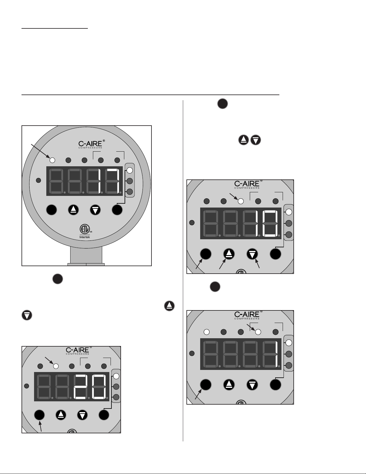
DIGITAL AMD OPERATING INSTRUCTIONS FOR S33 MODEL
This Digital AMD has 5 different modes of operation� When it is
powered on, it starts in the RUN mode and will display the current
pressure�
RUN MAX MIN
PSI
kPa
BAR
24HRS 7 DAY S
STARTS
SETTTINGS
LOCKED
C
PM
C
Pressing the
M
mode button once will switch it to the maximum
pressure setting, (or the pressure at which the compressor turns
off)� At this point you are able to adjust the maximum/turn off
pressure� When the MAX indicator is on, the arrow buttons
can perform a +1/-1 change to the set value� The
compressor will not run in this mode� If the compressor remains
in this mode for 60 seconds with no adjustments, it will
automatically revert back to the RUN mode� Range: 10-55 PSI�
RUN MAX MIN
PSI
kPa
BAR
24HRS 7 DAY S
STARTS
LOCKED
PM
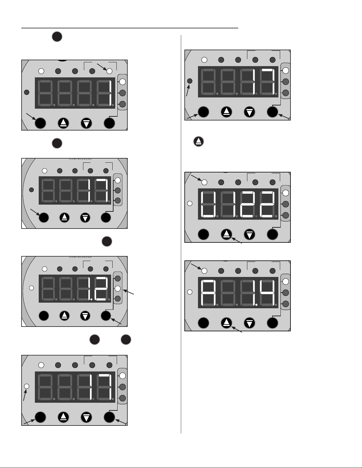
Pressing the
M
mode button a second time will switch it to the
minimum pressure mode, this is the minimum pressure the
system will reach before it turns on� At this point you are able to
adjust the minimum/turn on pressure� When the MIN indicator is
on, the arrow buttons can perform a +1/-1 change to
the set value� If the compressor remains in this mode for 60
seconds with no adjustments, it will automatically revert back to
the RUN mode� Range: 5-50 PSI� Note: the upper and lower
limits have a minimum differential of 5 PSI�
RUN MAX MIN
PSI
kPa
BAR
24HRS 7 DAY S
STARTS
LOCKED
PM
Press the
M
mode button a third time and the 24HRS indicator
will display the total number of starts in the last 24 hours (The
counter will not measure time if the unit has no power)�
RUN MAX MIN
PSI
kPa
BAR
24HRS 7 DAY S
STARTS
LOCKED
PM
(DIGITAL AMD INSTRUCTIONS CONTINUED ON NEXT PAGE)