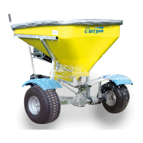
C-Dax SPREADMASTER User manual

OWNER’S MANUAL
FOR THE
SPREADMASTER
g e n e r a t i o n 2
MOUNTED SPREADER
C-Dax Ltd
PO Box 1010, 145 Hart Road
Tiritea, Palmer ton North
Ph:06 354 6060
Fax:06 355 3199
E-Mail: ale @c-dax.co.nz
www.c-dax.co.nz

- 2 -
SAFETY PRECAUTIONS
SPREADMASTER
AN IMPORTANT MESSAGE FOR OWNERS & OPERATORS OF
C-Dax ATTACHMENTS ACCESSORIES
Be warned of the danger of loading your ATV or other vehicle in exce of it carrying capacity.
It i important to under tand that any load or attachment whether fa tened to or placed on a
vehicle or ATV will alter the tability or handling characteri tic of that vehicle or ATV.
Spray tank or other equipment mu t be filled only to a level where the gro weight i within the
load limit of the ATV or other vehicle.
Safety i a primary concern in the de ign, manufacture, ale, and u e of pray tank and other
equipment. A manufacturer of pray tank and other equipment we want to confirm to you, our
cu tomer , our concern for afety. We take thi opportunity to remind you about the imple, ba ic
and common en e rule of afety when u ing pray tank and other equipment. Failure to follow
the e rule can re ult in evere injury or death to operator and by tander .
It i e ential that everyone involved in the a embly, operation, tran port, maintenance and
torage of thi equipment be aware, concerned, prudent and properly trained in afety.
Thi al o applie to equipment that i loaned or rented to omeone who ha not read the owner’
manual and i not familiar with the operation of application equipment.
• NEVER EXCEED THE LOAD LIMIT CAPACITY OF THE ATV OR OTHER VEHICLE.
• ALL ATV AND TRAILED EQUIPMENT TYRES SHOULD BE INFLATED TO
MANUFACTURERS RECOMMENDED OPERATING PRESSURES.
• PLEASE NOTE THAT FILLING THE SPRAY TANK OR OTHER EQUIPMENT COMPLETELY
AND OR THE ATTACHMENT OF ADDITIONAL EQUIPMENT TO THE ATV MAY EXCEED THE
ATV’S MAXIMUM LOAD CAPACITY, AND ADVERSELY AFFECT THE STABILITY OF THE
ATV OR OTHER VEHICLE.
• CARGO SHOULD BE PROPERLY DISTRIBUTED AND SECURELY ATTACHED.
• REDUCE SPEED WHEN CARRYING CARGO OR PULLING A TRAILER OR TRAILED
APPLICATION EQUIPMENT AND ALLOW GREATER DISTANCE FOR BRAKING.
• NEVER ALLOW ANYONE TO RIDE ON YOUR SPRAYER OR OTHER EQUIPMENT.
• ALWAYS FOLLOW THE INSTRUCTIONS IN THE OWNER’S VEHICLE MANUAL FOR
CARRYING CARGO OR PULLING A TRAILER.
• PROPER MAINTENANCE IN LINE WITH MANUFACTURER’S RECOMMENDED
MAINTENANCE PROCEDURES IS ESSENTIAL.
• BEFORE APPLYING CHEMICALS, READ THE LABEL OF THE CHEMICAL
MANUFACTURER OR SUPPLIER FOR PERSONAL PROTECTIVE EQUIPMENT AND
OPERATE AS RECOMMENDED.
• THE SAFETY OF ALL CHEMICALS USED IN AGRICULTURE IS UNDER THE JURISDICTION
OF A GOVERNMENT AGENCY, IE N.Z. MINISTRY FOR THE ENVIRONMENT; USA
ENVIRONMENTAL PROTECTION AGENCY. FURTHER LOCAL GOVERNMENT OR STATE
LAWS MAY APPLY.
Throughout thi manual there are highlighted text boxe containing warning , caution and note .
Warnings are mandatory in truction to prevent eriou injury or permanent damage.
Cautions are advi ory in truction to en ure reliable operation of the equipment.
Notes are for convenient operation
WARNING

3
For afe operation en ure that your vehicle i adequate for the ta k. The maximum tare weight i
60 Kg or a recommended by the vehicle manufacturer.
SAFTEY PRECAUTIONS CONT…
Read the in truction book thoroughly before attempting to in tall or operate the preader.
Failure to read the manual con titute mi u e of the equipment and will invalidate the
warranty.
The maximum loaded weight of the preader hould not exceed the manufacturer’ pecific
carrier weight limit.
Never turn the preader on if there i omeone tanding near the pinner.
Make ure the pinner i turned off and the hutter i clo ed before loading the hopper.
Never u e dirty product or product with tone or lump .
Never replace the fu e with one larger than the maximum recommended rating of 20 Amp .
If u ing the preader on hilly terrain, the payload hould be reduced to en ure that the
preader and vehicle tability are not compromi ed.
Never allow anyone to ride on the preader.
Keep the preader in good condition. Cleanline and maintenance are e ential for afe and
trouble free operation. Never leave product in the hopper or tore the preader without
cleaning it.

4
C-Dax SPREADMASTER G2
OWNER’S MANUAL
(Pt.No.2400-7000 I ue 10, Dated Dec 2010)
TABLE OF CONTENTS
2 Safety Precautions
3 Safety Precautions Cont.
4 Table of Contents
5 Introduction
Description
6 Specifications
Order Information
Optional Equipment
7 Warranty
Liability
8 Installation
Flatdeck
9 Quick Smart preader attachment
Quick Smart attachment y tem
Wiring
Operation
10 System Interconnections
Calibration
11 Calibration Guide
12 Operating the Spreader
Adju ting the Spread Pattern
Maintenance
Before U e
13 After Each Use or Daily When in Use
Repairs
Removal of the Motor
Removal of the Spinner
Removal of the Agitator Shaft
Removal of the Delivery chute
Removal of the Hopper
Removal of the Shutter
Rea embly
14 In talling a New Agitator Flail
Trouble Shooting
15 Exploded Parts Diagram
16 Parts List

5
INTRODUCTION
Congratulation on the purcha e of your new SpreadMa ter preading unit. You join the many
farmer’ world-wide who have recogni ed the remarkable u efulne of thi unique piece of
equipment.
DESCRIPTION
The C-Dax SpreadMa ter i de igned for accurate application of eed , fertili er , and powdered
product .
The uniquely de igned 70 Litre tran lucent non-corro ive polyethylene hopper i pecially profiled
for good product flow and ea e of filling. The convenient hinged polyethylene nap hut lid en ure
ecure product torage. A two- tage agitator and tainle teel hutter and choke a embly
en ure even and controlled flow of product to the pinner. A turdy convenient hutter handle
en ure po itive open and clo ed action of the hutter. A unique ix-vane tainle teel pinner
driven by a 12 VDC motor provide 180 degree pread of product.
The SpreadMa ter can be ordered in three configuration :
The SpreadMa ter can be bolted to a flat vertical urface uch a the tailboard of a trailer.
Part number 3000
The SpreadMa ter can be ordered with a Quick Smart y tem. Complete with the
convenient Quick Smart™ attachment y tem for the rear carrier of ATV and a Quick
mart preader bracket. Part number 3000, 1073 and 3008
The SpreadMa ter can be ordered with a Quick Smart preader bracket. Part number
3000 and 3008

6
SPECIFICATIONS
(Specifications subject to change without notice)
Dry Weight 20 Kg (Spreader Only)
Dimen ion Width 600 mm
Height 780 mm
Length 500 mm
Capacity 70 litre
Power Con umption 12 VDC 6.5 amp off load, 20 amp fully loaded
Drive 12 VDC motor with remote control witch
Control Adju table tainle teel lide choke
Shutter Manual control handle
Agitator Flexible upper arm, motor driven
Spinner Non-Corro ive, medium den ity, UV tabili ed
polyethylene
Hopper Non-corro ive polyethylene, ergonomically de igned
for ea e of filling and in pection
Hopper Lid Non-corro ive polyethylene nap hut
Frame Powder coated teel (Optional Galvani ed Frame)
Application Rate (Min) 1.6 Kg per hectare at 10 kph (nominal urea)
Application Rate (Max) 50 Kg per hectare at 10 kph (nominal urea)
Spread Width 15m (nominal urea)
ORDER INFORMATION
(Galvani ed Model ) SpreadMa ter Pt.No.3000
Quick mart preader attachment Pt.No.3008
Quick mart attachment y tem Pt.No.1073
OPTIONAL EQUIPMENT
Control Cable Extensions, 3 Metre Pt.No.1500-4700
If the Control Panel i to be placed at a di tance from the vehicle battery, the battery cable may
need to be extended. The cable can be cut and the optional connector et (Pt No.30008) in talled
on the end of the wire . The Male connector mu t be in talled on the Control Panel cable. Adding
a 1.5 metre or 3.0 metre exten ion cable can then extend the cable.

7
WARRANTY
C-Dax Ltd warrant to the original purcha er that the equipment i old free from defect in
material and workman hip for a period of 12 month from date of retail ale (6 Month from date
of retail ale for all equipment old in the U.K.). Accordingly, C-Dax Ltd undertake to repair the
equipment, or at our option replace, without co t to the original purcha er either for material ,
part or labour, any part which within the pecified warranty period from time of delivery i found to
be defective. PROVIDED that the equipment ha been u ed for normal purpo e in accordance
with the in truction , and ha not been ubject to neglect, mi u e or accident, and ha not been
repaired, erviced or di mantled by any per on other than a ervice agent or per on authori ed by
C-Dax Ltd.
The warranty doe not extend to cover: con equential damage; repair or replacement of part due
to fair wear and tear; or damage re ulting from neglect, mi u e, accident or hireage.
SPECIFICALLY the warranty exclude battery damage, damage ari ing from chemical attack, and
unit built to cu tomer pecification .
All good returned to C-Dax Ltd are freight paid by the sender and if ubject to a warranty claim,
must be accompanied by a completed warranty claim form. Warranty claim form are available
from C-Dax dealer .
LIABILITY
The maximum liability, which i accepted by C-Dax Ltd, i limited to replacement of faulty good
only. Every care ha been taken in the manufacture of our good but becau e u e of the good i
out ide the control of the manufacturer, the end u er a ume all re pon ibility for the u e.
Neither the manufacturer nor retailer hall be liable for lo or damage re ulting from u e.
Any advice or recommendation given by C-Dax Ltd, it agent , or employee i given in good
faith and ba ed on the be t information available to u . No liability or re pon ibility i accepted or
implied a a re ult of any information or advice tendered by C-Dax Ltd, it agent or employee .
The end u er accept all re pon ibility ari ing from that advice.

8
INSTALLATION
All Models
Unpack the preader and check the content . The following part are included;
Spreader Unit
Con ole
Owner’ Manual
Shutter Lever A embly
Shutter Lever Friction Wa her
If you have purcha ed a Quick mart and/or Quick mart preader frame you may al o have the
following.
QS Spreader Adaptor Bracket with attachment bolt and nut (4 et )
Quick Smart™ATV Bracket with attachment clamp and hardware (4 et )
In ert the hutter lever into the top bracket on the ide of the preader frame and apply pre ure
upward to compre the pring.
Locate the friction wa her over the pin at the bottom of the handle and in ert the pin into the
bottom bracket on the preader frame en uring that the hole in the end of the hutter lever i
located over the pin on the hutter arm on the preader.
Operate the hutter handle to check that the hutter move po itively and tay in the fully open
and clo ed po ition .
Flatdeck Mounting
Mark and drill four 8mm hole in the vertical urface where the machine i to be attached. Bolt the
machine in place u ing 8mm bolt of the correct length (client upplied). The minimum
recommended pinner height from the ground i 500mm.
CAUTION
For proper operation of the preader it i not recommended that it be bolted to a horizontal urface
without additional upport for the cha i . If mounting on a horizontal urface u e two ‘L’ bracket
(client upplied) to upport the rear of the frame.
NOTE
The preader will need to be in reach o that the operator can work the hutter handle.
Bolt the machine in place u ing 8mm bolt of the correct length (client upplied).

9
Quick Smart system mounting
In tall the Quick Smart™ attachment kit on the ATV a detailed in the in tallation in truction
provided in the kit.
Quick Smart spreader attachment
Attach the QS Adaptor Bracket to the preader u ing the M8x25 nut and bolt provided.
Attach the preader to the ATV by locking the adaptor bracket into the QS ATV bracket. En ure
that the bracket i correctly engaged under the latche .
Wiring
Place the con ole in the required po ition and connect the battery cable to the vehicle battery.
The red wire mu t be connected to the po itive terminal. Attach the con ole to the vehicle u ing
the elf adhe ive Velcro fa tener provided.
WARNING
To avoid injury en ure that the witch i in the OFF po ition before connecting cable .
Connect the con ole to the preader. En ure that any exce cable i towed where it cannot be
pinched or damaged.
Switch the preader on and check that the pinner turn clockwi e when viewed from the top. If
the pinner turn anti-clockwi e, rever e the polarity of the wiring. Your preader i now ready to
u e.
OPERATION
The product to be pread i placed in the hopper and the lid napped hut.
When the witch i turned on electrical power i upplied to the pinner motor. The pinner will
pin up to operating peed.
When the hutter handle i pulled toward the operator the hutter will open to a po ition
determined by an adju table top. Product will then flow from the hopper through an adju table
orifice into the delivery chute. At the ba e of the chute there are two delivery hole which en ure
that product enter the pinning di k at the correct po ition to pread the product behind the
preader over 180 degree .
An agitator haft in the bottom of the hopper en ure that product flow continuou ly through the
metering orifice, and en ure that product doe not bridge in the neck of the hopper.
CAUTION
The agitator flail may not be required for free-flowing product uch a granulated fertili er and
eed. To avoid overloading the motor the flail may be removed when the e product are being
applied.

10
SYSTEM INTERCONNECTIONS
CALIBRATION
Make ure the hutter i in the clo ed po ition.
If free flowing product are to be applied, configure the agitator to uit.
To calibrate your preader place a mea ured amount of product in the hopper.
Set the choke to po ition (1-9) a indicated in the Calibration Guide on the following page.
Drive the preader at the de ired peed and open the hutter.
When the product ha been exhau ted, mea ure the area covered in quare metre . It i
recommended that thi be done over an area where the product can be een on the ground o that
the pread width can be mea ured. A pla tic heet may be u ed.
Check the application rate u ing the following formula:
Rate (Kg ha) = Product applied (Kg) x 10,000
Distance travelled (metres) x spread width (metres)
Adju t either the choke or the peed of travel until the de ired application rate i achieved.
Con ole
Spreader
Connect to battery, en uring red wire i
connected to the po itive terminal
Battery cable may be extended by
inserting a connector set then adding a
standard extension cable
20A Fu e (Max Rating)

11
CALIBRATION GUIDE
(Average Speed 10 Kph)
NOTE
Becau e of variation in product characteri tic , peedometer calibration and driving peed, the
information in the calibration guide hould be regarded a a tarting point only. It i recommended
that the preader be calibrated before each u e.
CAUTION
To avoid damage to the motor, application rate in exce of 50 Kg per hectare are not
recommended.
Product Rate (Kg ha) Choke Settings Nominal Spread
(metres)
Rye Gra 40 2 7
Rye Gra 35 3 7
Rye Gra 31 4 7
Rye Gra 20 4.5 7
Rye Gra 12 5 7
Turnip 4.5 7.5 14
Turnip 4 8 14
Turnip 1 8.5 14
Clover 10 7.5 10
Clover 9.5 8 10
Clover 4 8.5 10
Clover 0.5 9 10
Cropma ter 53 4 15
Cropma ter 37 5 15
Cropma ter 25 6 15
Urea 48 3 15
Urea 30 4 15
Urea 19 5 15
Super Pho phate 40 4 15
Super Pho phate 27 5 15
Du ting Grade Cau mag pread at a rate of 4kg per minute at hutter etting 0
CAUTION
It i not recommended to exceed choke etting #3 with urea or motor damage due to overloading
could occur.

12
OPERATING THE SPREADER
When the preader ha been correctly calibrated and the agitator configuration adju ted for the
product to be pread, the hopper may be filled to the required level and preading commenced.
To prevent agitator damage to the product and inadvertently operating of the hutter, it i
recommended that the pinner i turned off until area to be covered i reached.
Flick the witch on the con ole to ‘on’ to apply power to the machine and tart the pinner.
WARNING
Some product may compact around the agitator in the hopper whil t in tran it. If thi occur the
motor may be overloaded when witching on for the fir t time. It i therefore recommended that the
pinner be checked for free movement if the preader ha been driven for any ignificant di tance
with product in the hopper and the motor witched off.
Pull the hutter lever toward the operator to commence preading product.
Adjusting the Spread Pattern
The preader ha been factory- et for urea. When preading other product you may want to
adju t the centring of the pread pattern. Thi i achieved by loo ening the Jubilee clip beneath
the hopper upport plate, rotating the delivery chute to a new po ition and tightening the clip again.
To return the chute to the factory etting imply align the right hand edge of the right hand aperture
with the calibration hole on the under ide of the hopper upport plate.
Chute po ition hown in factory etting
WARNING
Never adju t the delivery chute with the preader turned on.
Never place hand or loo e clothing near a revolving pinner or motor haft.
CAUTION
To avoid damage to the pinner and motor and to en ure that the preader perform well, en ure
that there i alway a 2.5 mm gap between the pinner ba e and the delivery chute. Too mall a
gap may cau e interference between the pinner and chute and too large a gap may cau e
product to leave the chute at the wrong po ition and effect the accuracy of the pread pattern.
MAINTENANCE
CAUTION
The following maintenance action are mandatory for reliable u e of the preader.
Before Use
Turn the pinner by hand to en ure that it i free to turn without interference.
Check the hopper to en ure that no debri i in ide.
Check that the agitator ha been correctly configured. For free flowing product the agitator may
be removed.
Thi edge and hole are aligned

13
After Each Use or Daily When in Use
Remove all trace of product from the preader by wiping. Pay particular attention to area where
product ha accumulated and built up. If removing product by craping take care not to damage the
urface fini h of the preader or it component .
Do not direct water onto the motor hou ing (thi area hould be wiped clean).
After cleaning, apply water-di placing fluid uch a WD40 to all metal part .
Check for damaged or worn component and replace a required.
REPAIRS
Removal of the Motor
Locate the motor haft grub crew in the rece in the pinner bo .
Apply a little heat with a clean oldering iron to often the thread-locking compound.
U ing 2 mm Allen key loo en the motor haft grub crew.
Remove the cover from the electric connector and loo en the clamp crew to remove the wire
from the connector.
U ing a 3/16 UNF panner remove the motor mounting nut .
Withdraw the motor from it mounting.
Removal of the Spinner
Remove the motor a de cribed above.
U ing a oldering iron apply a little heat to the grub crew to often the thread locking compound.
U ing a 2mm Allen key loo en the two pinner grub crew and remove the motor haft grub crew
entirely.
Remove the pinner from the agitator haft.
Removal of the Agitator Shaft
Remove the motor, and pinner a de cribed above.
Leave the agitator flail on the agitator haft.
Withdraw the haft upward through the hopper mount plate.
NOTE
If the motor haft cannot be withdrawn from the agitator haft, the agitator flail, and wa her may be
removed fir t and the motor, and agitator haft may be removed a a unit through the bottom of
the frame once the pinner grub crew have been loo ened.
Removal of the Delivery Chute
Mark the po ition of the delivery chute with re pect to the cha i .
Relea e the clamp ecuring the chute to the chute ring.
Remove the delivery chute.
Removal of the Hopper
Remove the two bolt ecuring the hopper to the cha i .
Lift the hopper clear of the cha i .
Removal of the Shutter
Remove the hopper a de cribed above.
Lift the control handle again t it pring pre ure to di engage the handle from the hutter and the
lower pivot bracket.
Retain the friction wa her from the lower pin on the handle.
Unthread the handle through the upper bracket.
U ing a 10mm panner undo the four nut ecuring the hopper mount plate.
Lift the plate clear.
Withdraw the hutter.
The hutter guide plate may be removed at thi point.

14
Reassembly
The above procedure may be rever ed to rea emble the preader.
En ure that the friction wa her i in place when rea embling the hutter lever a embly to the
frame.
When the delivery chute i in talled it mu t be fixed in the ame po ition a the original.
When the pinner ha been in talled the clearance between the pinner and the delivery chute
mu t be et to a maximum of 2.5mm.
Installing a New Agitator Flail
The flail a embly come complete with retaining clip . In ert the new flail though the hole in the
agitator haft.
Thread on the retaining clip o that the flail i held ecurely.
U ing a pair of plier , cru h the clip onto the flail.
En ure that the new flail cannot contact the wall of the hopper. Trim to length if required.
TROUBLE SHOOTING
Spinner does not turn when the switch is turned on
Wiring not connected - Check connection
Fu e ha blown - Check fu e
Product ha jammed agitator - Empty hopper and clear
Delivery chute touching pinner - Adju t clearance gap
Product jamming pinner - Check hutter i clo ed and clear product
- Check the chute clearance gap to 2.5mm
Fuse blows each time the spreader is operated
Spinner jammed - Check pinner/chute clearance gap, et to 2.5mm
Product compacted around agitator - Remove compacted product or pin the
pinner by hand before applying power
Application Rate too high - Increa e the choke etting
Wiring i damaged - Check and repair a required
Exce ive load on motor - Check agitator configuration
- Check product i not clogged in ba e of hopper
WARNING
To avoid eriou damage to the motor and wiring, never replace the fu e with one rated higher
than 20 Amp .
Spinner is running, the shutter is open, but there is no product being spread
No product in hopper -Turn off and fill hopper
Product i bridging acro orifice - Empty hopper and fill with fre h product
Choke i hut or adju ted too high - Correctly calibrate choke
Shutter lever won’t stay in position
Shutter friction incorrect - Check that the friction wa her i correctly
located between the lower lever arm and the
lower bracket on the frame.
Product spread is uneven
The delivery chute i too far to
one ide - Adju t the chute to achieve even pread
Product build up in delivery chute - Clean product off preader

15
Product throws forward
Product e caping from delivery chute - Check chute/ pinner clearance gap, et to 2.5mm
Spread pattern centred incorrectly - Adju t pread pattern centering

- 16 -
EXPLODED PARTS DIAGRAM

- 17 -
NOTES
Table of contents
Other C-Dax Spreader manuals