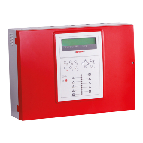
EACIE Evacuation Alert Control and Indicating Equipment
Page 3 of 38 Approved Document No. DFU5030020 Rev 1 Installation and Programming Manual
7.4.1 Device Manager ....................................................................................................................................23
7.4.2 Show PSU Status ...................................................................................................................................... 25
7.4.3 Test Output Group ..................................................................................................................................25
7.4.4 Show Loop Status.................................................................................................................................... 25
7.4.5 Find Loop Break ......................................................................................................................................26
7.4.6 Change Access Level 2 (AL2) Code..................................................................................................... 26
7.4.7 Change Access Level 3 (AL3) Code..................................................................................................... 26
7.4.8 Show System Details ............................................................................................................................... 26
7.4.9 Clean Start ..............................................................................................................................................26
7.5 COMMISSIONING FUNCTIONS ..................................................................................................................27
7.5.1 Loop Learn ..............................................................................................................................................28
7.5.2 Auto Address........................................................................................................................................... 28
7.5.3 Fix Address Faults ....................................................................................................................................29
7.5.4 Verify Loop .............................................................................................................................................. 29
7.5.5 Device Manager .................................................................................................................................... 29
7.5.6 Add New Device .................................................................................................................................... 29
7.5.7 Add/Delete/Edit a Device..................................................................................................................... 29
7.5.8 Edit Zone Name ......................................................................................................................................30
7.5.9 Edit Output Group Name....................................................................................................................... 30
7.5.10 Setup Networking ................................................................................................................................... 30
7.5.11 Synchronise Network Data..................................................................................................................... 30
7.5.12 Set Loops Fitted....................................................................................................................................... 30
7.6 EVENT LOG FUNCTIONS..........................................................................................................................31
7.7 SET THE PANEL’S TIME AND DATE..........................................................................................................32
7.8 SHOW SUPERVISORY EVENTS .................................................................................................................32
8MAINTENANCE......................................................................................................................................33
APPENDIX 1 –PROTECTIVE CABINET AND EACIE PANEL DIMENSIONS ........................................34
APPENDIX 2 –EACIE PANEL PROGRAMMING MODULE ...................................................................34
APPENDIX 3 –STANDBY BATTERY CALCULATION.............................................................................35
APPENDIX 4 –FITTING THE 2-LOOP PCB (OPTIONAL).......................................................................35
APPENDIX 5 –EACIE PANEL TECHNICAL SPECIFICATION..............................................................36
APPENDIX 6 –GLOSSARY OF TERMS.......................................................................................................37
Figures
Figure 1 –Typical EACIE Panel PCB Connections...............................................................................................7
Figure 2 –Location of EACIE Panel Components.................................................................................................9
Figure 3 –Protective Cabinet and EACIE Panel Mounting Location ..................................................................10
Figure 4 –Protective Cabinet Wall Mounting and EACIE Panel Fitting .............................................................11
Figure 5 –Typical EAS Loop Overview..............................................................................................................14
Figure 6 –Analogue Addressable Loop Connections ..........................................................................................15
Figure 7 –Relay Output Detail.............................................................................................................................16
Figure 8 –PC Connection.....................................................................................................................................16
Figure 9 –5A PSU Layout and Mains Connection Details ..................................................................................17
Figure 10 –Battery Connection Details ...............................................................................................................18
Figure 11 –Access Level 3 Menu Structure.........................................................................................................21
Manufacturer: Computionics Limited (C-TEC), Challenge Way, Martland Park, Wigan, Lancashire WN5 0LD. www.c-tec.com
