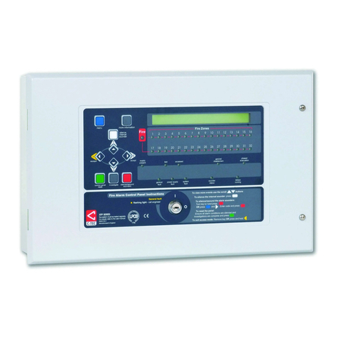
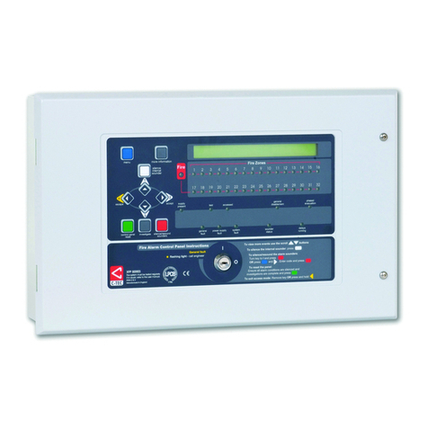
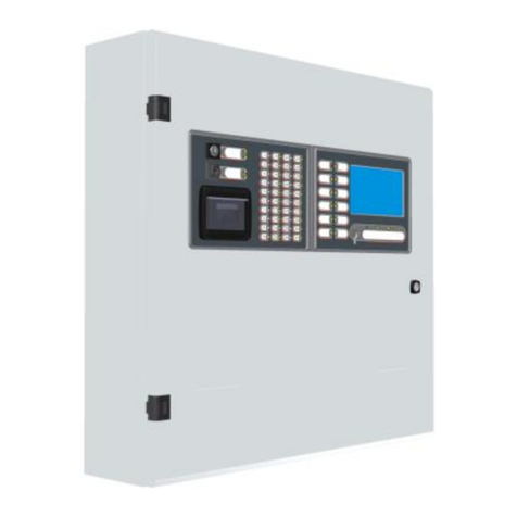
C-TEC CAST XFP Installation and operation manual

CAST XFP
Networkable
Analogue Addressable
Fire Alarm Control Panel
1 Loop, 16 Zone Panel
Part No. XFP501E/CA
Engineering
Manual
Approved Document No. DFU5010000 Rev 4

CONTENTS
Important notes................................................................................................................................... 3
Key features......................................................................................................................................... 4
Installation and wiring........................................................................................................................ 5
The fire panel enclosure.................................................................................................................................. 5
Removing the lid and base PCBs..................................................................................................................... 5
Mounting the base onto a wall ...................................................................................................................... 6
Planning the cable layout in the panel.......................................................................................................... 6
Mains wiring..................................................................................................................................................... 6
Connecting Mains to the Power Supply PCB ................................................................................................. 7
Analogue addressable loop wiring................................................................................................................. 8
Connecting the analogue loop to the Main Control PCB............................................................................. 9
Conventional sounder circuit wiring ............................................................................................................ 10
Auxiliary input wiring.................................................................................................................................... 10
Relay output wiring....................................................................................................................................... 10
Remote PC connection................................................................................................................................... 11
Aux. 24V output............................................................................................................................................. 11
Installing the standby battery supply ........................................................................................................... 11
Network/repeater wiring (optional) ............................................................................................................. 12
Controls and indicators..................................................................................................................... 14
Commissioning and programming................................................................................................... 16
Recommended commissioning procedure ................................................................................................... 16
Access levels menu structure.................................................................................................................... 16-17
How to enter access level three.................................................................................................................... 18
Fitting the panel’s NVM ‘memory unlock’ link ............................................................................................ 18
A detailed description of the functions available at access level 3....................................................... 19-46
Maintenance ...................................................................................................................................... 46
Standby battery calculation guide................................................................................................... 46
Technical specification ...................................................................................................................... 47
E&OE. Errors & Omissions Excepted. The manufacturer of this product operates a policy of continuous improvement
and reserves the right to alter product specifications at its discretion and without prior notice. All of the instructions
covered in this manual have been carefully checked prior to publication. However, no responsibility can be accepted by
the manufacturer for any inaccuracies or for any misinterpretation of an instruction or guidance note.
ENGINEERING MANUAL • Approved Document No. DFU5010000 Rev 4 • Page 2 of 48
CAST XFP 16 ZONE ANALOGUE ADDRESSABLE FIRE ALARM PANEL
Manufacturer: Computionics Limited (C-TEC), Challenge Way, Martland Park, Wigan, Lancashire WN5 0LD. www.c-tec.com
Niederlassung Deutschland: C-TEC Germany Limited, Virchowstr. 32, D-33332 Gϋtersloh. www.c-tec-germany.de
CAST XFP 1 Loop, 16 Zone (XFP501E/CA)
2831-CPR-F2522
176b 2831 19

IMPORTANT NOTES
This equipment MUST only be installed and maintained by a suitably skilled and
technically competent person. Ensure you have attended C-TEC’s Authorised Training
Course before handling the panel.
This equipment is a piece of Class 1 permanently connected equipment and MUST BE EARTHED.
CAUTION: DO NOT connect or disconnect the panel’s internal wiring / looms, or terminate
field wiring at the PCBs, with the panel’s power applied (either Mains or battery). Failure to
observe this WILL destroy the panel’s electronic components and the warranty will be void.
Items supplied with this panel
• Engineering manual (Document No. DFU5010000). This manual MUST NOT be left accessible to the user.
• User Manual / Log Book (Document No. DFU5020000)
• Key for unfastening / securing the panel lid
• Electrical accessory pack containing:
6K8 0.25W EOL resistors for the two conventional sounder circuits
T 1A H 250V 20mm ceramic fuse (spare primary fuse)
1.6A F 20mm ceramic fuse (spare battery fuse)
Battery connection kit (red wire, black wire, green link wire and cable ties)
System design
Fire alarm system design is beyond the scope of this document. A basic understanding of general fire
alarm system components and their use is assumed. Contact the Fire Officer concerned with the property
at an early stage in case there are any special requirements. We strongly recommend that a suitably
qualified and competent person is consulted regarding the design of the fire alarm system and that
the system is commissioned and serviced in accordance with the laid down specification and national
standards. In the UK, we recommend you read BS 5839: “Fire Detection and Alarm Systems for Buildings
(Code of Practice for System Design, Installation, Commissioning and Maintenance)”. Other national, or
local standards of installation should be referenced where applicable.
Cable types and limitations
All system wiring should be installed to meet national standards - in the UK these are
BS 5839 Part 1 and BS 7671 (Wiring Regulations). Fire-resistant, screened cable should be used
throughout the installation. For network wiring 2-core screened, enhanced fire-resistant cable is
recommended. This not only shields the data moving through the cables from outside interference but
is essential to ensure compliance with EMC regulations. Cables such as FP200, Firetuf, Firece and MICC
may be acceptable provided they meet national standards / the system specification.
EN54 Compliance Statement
This fire alarm panel is fully compliant with the requirements of EN54 Part 2 (Fire detection and fire alarm
systems, control and indicating equipment) and EN54 Part 4 (Fire detection and fire alarm systems, power
supply equipment) and is certified as meeting these standards by the Loss Prevention Certification Board
(LPCB) - unless stated.
Note that some of the engineer functions provided on the panel go beyond the scope of EN54-2.
A caution symbol (left) is used to indicate where such a function is non-compliant with EN54-2.
DO NOT affix the LPCB approval label (supplied) to the front of the panel if it has been configured to
operate in a way that would make it non-compliant with the requirements of EN54-2.
Equipment guarantee
This equipment is NOT guaranteed unless the complete installation is installed and commissioned in
accordance with the laid down national standards (in the UK this is BS 5839: Part 1) by an approved
and competent person or organisation.
Anti-static handling guidelines
Always observe appropriate electro-static handling guidelines before handling the panel’s
PCBs, or any other static-sensitive components.
ENGINEERING MANUAL • Approved Document No. DFU5010000 Rev 4 • Page 3 of 48
CAST XFP 16 ZONE ANALOGUE ADDRESSABLE FIRE ALARM PANEL
Read these instructions thoroughly before installation and operation
General Warning Sign Danger Electrical Hazard
Symbols
KEY FEATURES
The CAST XFP 1 loop 16 zone analogue addressable fire alarm panel (Part No. XFP501E/CA) is
designed for use with fire and security systems and offers the following features:
• Certification by the LPCB to EN54 parts 2 and 4.
• Full compatibility with C-TEC’s CAST®(C-TEC Addressable System Technology) - a powerful,
proprietary communication protocol.
• Short-circuit protected loop driver (rated at 500mA, 40V), capable of supporting up to 255
addressable CAST devices. Each CAST loop device is fitted with a short-circuit isolator.
• Two CAST device addressing options - automatically by the panel (AUTO ADDRESS & LOOP LEARN
functions), or manually using the CAST Handheld Programmer (Part No. CAPROG).
• Ability to change a device’s address.
• Ability to detect and fix duplicate addresses.
• Ability to detect swapped loop devices.
• Ability to turn all device polling LEDS on/off.
• Fast response time from fire detection to multiple output groups.
• Two independently programmable conventional sounder circuits.
• Two programmable auxiliary inputs.
• A fault relay output and three programmable relay outputs with volt-free changeover contacts.
• A selection of zone dependency functions (EN54-2 Clause 7.12, type A, B or C) as detailed below:
Type A - If there is an alarm from a detector, the panel will look for a confirmatory alarm from
the same, or another, detector in the same zone before a full alarm is established. If there is no
confirmatory alarm, the first alarm will automatically reset.
Type B - As type A except the confirmatory signal must be from another detector in the same zone.
Type C - As type A except the confirmatory signal may also be from another zone and the first
alarm will not automatically reset.
• A day (building occupied) and night (building unoccupied) time function.
• An investigation delay period function (programmable for length of time, which zones it applies
to and whether or not it operates in day/night mode).
• Individual sensitivity settings for each device.
• EN54-2 Clause 7.8 re-sounding fire alarm devices.
• EN54-2 Clause 7.11 delays to outputs and a phased evacuation facility.
• EN54-2 Clause 7.13 alarm counter to record the number of alarm states (maximum of 999 counts).
• EN54-2 Clause 8.3 reporting of faults from heat detectors, optical detectors & multi-detectors.
• EN54-2 Clause 9.5 disablements of addressable points individually.
• An integral 1.5A EN54-4 switched mode PSU.
• Earth fault monitoring.
• Keypad code to enter levels 2 & 3. Keyswitch entry to access level 2.
• 40 characters of custom text per device.
• Comprehensive EN54-2 Clause 10 test, with maintenance and commissioning functions.
• Windows based PC programming tools (Part No. XFP507) that MUST be used to configure the system.
ENGINEERING MANUAL • Approved Document No. DFU5010000 Rev 4 • Page 4 of 48
CAST XFP 16 ZONE ANALOGUE ADDRESSABLE FIRE ALARM PANEL
Networking (Optional)
If required, the panel can be configured to sit on a non-redundant network of up to eight connected
CAST XFP main panels (any variant), OR you can have up to eight XFP repeaters connected to one non-
networked CAST XFP main panel. If you want to utilise either of these options, the panel will require a
separately available network driver card (Part No. XFP761). See page 12 for details.
Note: The CAST XFP network and XFP repeaters
have not been assessed to EN54-2.

INSTALLATION AND WIRING
The fire panel enclosure
The panel is supplied with a plastic detachable lid, plastic back box, Main Control PCB and a Power
Supply PCB. Space is available inside the panel for the rated capacity of VRLA backup batteries and an
optional network driver card.
The panel MUST be installed indoors, positioned to avoid accidental damage, and NOT subject to
conditions likely to affect its performance, e.g. dust, conductive or corrosive gases or liquids, nor
subject to temperatures, input voltages and electrical loads outside the stated operating range.
It should be sited at a height where it is easily accessible and in a prominent position within the
building. Ideally, its front panel indicators should be at eye level. Typical locations for the panel are
in the entrance foyer/hallway at ground floor level (the first and most obvious point of contact for
emergency services), or a permanently manned security office.
It is recommended that you remove the panel’s lid and base PCBs before first fix installation to protect
the electronics from damage (see Fig.1 below).
Removing the lid and base PCBs
Fig.1 : Location of the panel’s base PCBs and removal details
ENGINEERING MANUAL • Approved Document No. DFU5010000 Rev 4 • Page 5 of 48
CAST XFP 16 ZONE ANALOGUE ADDRESSABLE FIRE ALARM PANEL
MAIN CONTROL PCB
POWER SUPPLY PCB
PL1
PL1
To
disconnect
push tab
and gently
lift cable
PL1
PL1
Base Earth
Distribution
Post
Leave this end of the connector cable connected
to the rear of the Main Control PCB
• Undo the two lid screws using the key provided. Remove the lid to access the Main Control PCB
(the Power Supply PCB is located underneath).
• Carefully remove the five retaining screws on the Main Control PCB and slide the PCB up and
over its mounting pillars, taking care not to damage any of the components.
• Disconnect the telecoms-style connector cable from PL1 on the Power Supply PCB, making sure
that the cable remains connected to the rear of the Main Control PCB to prevent it being misplaced.
• Pull the Power Supply’s earth distribution strap off the spade connector at the base earth
distribution post.
• Carefully remove the three retaining screws on the Power Supply PCB and slide the PCB up and
over its mounting pillars, taking care not to damage any of the components.
• Store the PCBs in a clean, dry place which is free from vibration, dust and excessive heat.
Retaining the PCBs in a suitable cardboard box will also guard them against mechanical damage.
CAUTION: ISOLATE THE PANEL’S MAINS AND BATTERY SUPPLIES BEFORE REMOVING
THE LID AND BASE PCBs.

75mm
WALL
Mounting the base onto a wall
The panel can be surface, or semi-flush mounted onto a vertical wall, ≤2m mounting height, using the
five mounting holes provided (see Fig.2 below). To access the mounting holes, first remove the panel’s
lid and base PCBs, as detailed on page 5. The mounting holes are suitable for use with No.8-10 or 4-5mm
countersunk screws. Always assess the condition and construction of the wall and use suitable screw
fixings for the in-service weight of the product. Any dust or swarf created during the fixing process must
be kept out of the base. Note that the central mounting hole can be used to temporarily hang the back
box so it can be levelled and its remaining fixing points marked for drilling.
Fig.2 : Location of mounting holes and drill points / side view of panel for flush mounting
Do not drill any additional holes
for cable entry in this shaded area.
This is where the PCBs and
backup batteries will be located.
339mm
170mm
Fixing centres
Fixing centres
BASE TOP
BASE
These four drill
centre points
are reserved for
incoming Mains
cable only.
Planning the cable layout in the panel
All cables should be brought into the panel via the drill outs provided.
Note that the analogue loop and conventional sounder circuit cabling is classed as extra low voltage
and MUST be segregated away from Mains voltages. Careful planning is needed to ensure this. We
recommend tails of at least 20-30cm are left inside the panel to ensure straightforward connection of
the field wiring to the panel’s terminals.
Drill centre points are provided in the panel base to aid drilling tools. Cut out suitable holes in the panel
using a hole saw directed by a pilot bit in the centre of the hole saw. Always ensure if a hole is cut out
it is filled with a good quality strain relief cable gland. Any unused holes must be securely blanked off.
Mains wiring
All wiring should be installed in accordance with the current edition of the IEE Wiring Regs. (BS 7671), or
relevant national standards. The minimum requirement for the Mains supply to the panel is fixed wiring
(no less than 1mm2and no greater than 2.5mm2), either using 3-core cable, or a suitable three conductor
system fed from an isolating switched fused spur at 3A, or a 6A Type B circuit breaker to IEC/EN60898-1.
The Mains supply MUST be exclusive to the panel and be reliably earthed at the indicated earthing post.
As an alternative to a switched fused spur, a double-pole isolating switch (S), with 3mm air gaps on the
contacts & switching L & N only, may be used in the Mains feed from the Main Distribution Board (A) to
the Panel (C), providing it meets the appropriate wiring regulations (see drawing below).
ENGINEERING MANUAL • Approved Document No. DFU5010000 Rev 4 • Page 6 of 48
CAST XFP 16 ZONE ANALOGUE ADDRESSABLE FIRE ALARM PANEL
A
S
C
≥1.0 mm2<2.5 mm2
Hint! C-TEC’s Fire Alarm Control
Panel Mains Keyswitch (Part No.
BF319) is a lockable, double-
pole keyswitch that provides
secure switching of mains supply
to a fire alarm panel (BF319 is
available @ www.c-tec.com).

Connecting Mains to the Power Supply PCB
The panel’s PSU combines the functions of a power supply unit, battery charging unit, battery monitoring
unit and earth fault monitoring unit. It is positioned in the panel’s enclosure as shown in Fig.3 below.
CAUTION: DO NOT CONNECT MAINS TO THE POWER SUPPLY PCB UNTIL THE INSTALLATION IS
COMPLETE AND ALL RELEVANT PCBs ARE CORRECTLY FITTED IN THE PANEL.
ENGINEERING MANUAL • Approved Document No. DFU5010000 Rev 4 • Page 7 of 48
CAST XFP 16 ZONE ANALOGUE ADDRESSABLE FIRE ALARM PANEL
Fig.3 : Power Supply PCB layout and Mains connection (Full Protective Cover & Cable Cover shown fitted)
C
C
C
C
C
C
C
C
C
C
C
C
C
C
ON
O
ON
ON
ON
ON
ON
ON
N1
N1
N1
N1
N1
N1
N1
N
N
N
N
N
N
N
N
L
L
L
L
L
L
CONN2
BLK-RED+
VR1
F2
F1.6A
PL2
PL1
F
F
F1
F
F
1A
1A
2
2
2
50V
50V
0V
50V
50V
50V
50V
H
H
H
RC
RC
C
RC
C
C
RC
F1
F
F
F
V
V
V
HRC
F
F1 1A
2
0
50
250
0
0V
V
0V
V
V
V
V
HRC
V
0
V
V
0
HR
R
V
V
0V
1
A 250
R
1A
R
THIS
WAY UP
Incoming Mains Cable
This cable MUST be segregated from
other cables. Good quality cable
glands MUST always be fitted.
Primary Fuse (F1)
Exposed Live
parts under
fuse cover.
Isolate before
removal.
Battery Connector
(CONN2)
(Leads supplied in
the panel’s accessory
pack). See page 11 for
connection details.
Mains Input (CONN1)
L = Live (BROWN)
N = Neutral (BLUE)
= Earth (GREEN/YELLOW)
The incoming Mains earth wire MUST
be connected to the terminal marked
and NOT to the base earth distribution
post.
CONN1
NL
Cable cover
removed
PSU Earth Distribution Strap
This strap MUST be connected
to the spade on the
base earth distribution
post before operation.
Battery Fuse (F2)
Connector Cable Socket (PL1)
Connect other end of lead to
the rear of Main Control PCB.
WHEN THE RED ‘HAZARDOUS
VOLTAGES PRESENT’ LED IS LIT
HAZARDOUS VOLTAGES ARE
PRESENT UNDER THE TWO COVERS.
ALLOW TO DISCHARGE FOR AT LEAST 5
MINUTES BEFORE REMOVAL & HANDLING.
nut
3 x plain
washer
Do not untighten lower nut
spring
washer
Base Earth Distribution Post
PSU Earth
Distribution
Strap
Exposed live parts under cable
cover. Isolate first, then remove
the small cable cover by loosening
its single retaining screw which is retained
in the cover. Only operate the PSU with
this cover securely fitted.

Analogue addressable loop wiring
Fig.4 below shows a typical analogue addressable loop complete with detectors, manual call points,
loop-powered sounders/VADs and I/O units. Connect the loop to the relevant 5mm connector block on the
Main Control PCB and terminate screens at the panel’s base earth distribution post, as detailed on page 9.
Fig.4 : Typical analogue addressable loop
Polling
Active InputFault
CAST Zone
Monitor Unit
Conventional manual call points & detectors
Polling
Active InputFault
CAST I/O Unit
Fire Output
Fault Input
InputFault
Polling
Active
CAST Mains Switching
I/O Unit
Mains Switching Output
Monitored Input
CAST XFP 1 LOOP
16 ZONE MAIN PANEL
Auxiliary Input 1 (programmable)
Auxiliary Input 2 (programmable)
Conventional Sounder Circuit 1 (programmable)
Conventional Sounder Circuit 2 (programmable)
Relay Output 1 (programmable)
Relay Output 2 (programmable)
Relay Output 3 (programmable)
Fault Relay Output
100mA, +24Vdc Output
CAST Mini I/O Unit
Relay Output
Monitored Switch Input
Compact Sounder or VAD
or Sounder VAD
Base Sounder or VAD
or Sounder VAD
Base c/w Detector
Hi-Output Sounder
or Sounder VAD
Manual Call Point
CAST Loop Devices
Detector c/w mounting
base on Sounder/VAD
Loop 1
LOOP 1 A (OUT) LOOP 1 B (RETURN)
Design issues - reducing faults and their consequences
To ensure a reliable system, it should be designed and maintained to local design and installation
regulations. The CAST XFP panel has a short circuit protected loop driver fitted and also short circuit
isolators fitted in every CAST loop device. A single short circuit or open circuit fault will have no detrimental
affect on the operation of the system but a loop integrity fault will be shown at the panel.
Note that a critical design issue with any analogue fire system is the combined affect of loop resistance,
loop capacitance and the current demand of devices connected to the loop. Factors that influence this
include loop length, cable diameter, cable type and the number and type of devices. There are no hard
and fast rules regarding these factors as every situation is unique. However, if the following general
rules of thumb are followed, the loop WILL almost certainly work.
• Absolute maximum loop length = 1km, with either 1mm2or 1.5mm2cables.
• If loop sounders are required, use 1.5mm2cable and DO NOT fit more than the maximum circuit rating
detailed in the technical specification (see page 47).
The above SHOULD NOT be considered the maximum panel operating conditions as many other
permutations are possible. Always refer to the supplied device instructions before installation.
Hint! An XFP Loop & Battery Calculator Tool is available for download on C-TEC’s website in
the Support Hub to assist with system designs (available @ www.c-tec.com).
ENGINEERING MANUAL • Approved Document No. DFU5010000 Rev 4 • Page 8 of 48
CAST XFP 16 ZONE ANALOGUE ADDRESSABLE FIRE ALARM PANEL
Hint! Refer to www.c-tec.com.
for C-TEC’s CAST range of
compatible devices.

Connecting the analogue loop to the Main Control PCB
One analogue loop is provided which is capable of supporting up to 255 addressable devices.
The analogue loop should be connected to the Main Control PCB terminals marked: A+, A- (LOOP
1A OUT) and B+, B- (LOOP 1B RETURN), as shown in Fig.5 below. The loop’s earth screens should be
connected to the base earth distribution post.
Note that the Main Control PCB connects to the Power Supply PCB via an 8-way telecoms-style connector
cable, the socket for which is located on the PCB’s rear. This cable MUST be connected before the Main
Control PCB is secured in the panel.
Note about earthing of screens
All screens should be adequately insulated and connected between the nut and washers on the
base earth distribution post using crimp connectors. The base earth distribution post is provided for
terminating earth screens or drains and is NOT the main earthing point. The installer must review the
external earth bonding (if required) with respect to the national wiring rules. If the installation requires
protective earth bonding, then this must be applied externally and in conjunction with the type of
earthing system employed on site.
Fig.5 : Typical analogue addressable loop connection
GENERAL
FIRE ZONE 1 ZONE 2 ZONE 3 ZONE 4 ZONE 5 ZONE 6 ZONE 7 ZONE 8
ZONE 9 ZONE 10 ZONE 11 ZONE12 ZONE 13 ZONE 14 ZONE 15 ZONE 16
SUPPLY
PRESENT TEST ACCESSED
GENERAL
DISABLEMENT
PHASED
EVACUATION
GENERAL
FAULT
PSU
FAULT
SYSTEM
FAULT
SOUNDER
STAT US
DELAYS
RUNNING
Auxilliary
+24V I/P1 I/P2 0v
Relay 1
NC C NO
Relay 2
NC C NO
Relay 3
NC C NO
Fault
NC C NO
Sounder Circuits
+ 1 - + 2 - Earth Fault Detect
REMOVING THIS CIRCUIT
BOARD EXPOSES HAZARDOUS
VOLTAGES - PLEASE REFER TO
INSTALLATION INSTRUCTIONS
WARNING
SENSITIVE TO STATIC
ELECTRICITY - OBSERVE
PRECAUTIONS BEFORE
HANDLING
CAUTION - RISK OF EXPLOSION IF
INCORRECT TYPE OF BATTERIES FITTED.
DISPOSE OF USED BATTERIES ACCORDING
TO THE MANUFACTURERS INSTRUCTIONS. FOR OPERATIONAL DETAILS PLEASE
CONSULT THE MAINTENANCE MANUAL
Mute
Beeper
AB
+-+-
nut 3 x plain
washer
crimped
connection
Do not untighten lower nut
spring
washer
screens
Base Distribution Earth Post
PSU Earth
Distribution
Strap
Analogue Loop
LOOP 1A (OUT)
LOOP 1B (RETURN)
END A+
END A-
END B-
END B+
Earth
CONN1
Program
PLK3
Memory
Unlock
Connector cable (connects
from rear of Main Control PCB
to PL1 on Power Supply PCB)
ENGINEERING MANUAL • Approved Document No. DFU5010000 Rev 4 • Page 9 of 48
CAST XFP 16 ZONE ANALOGUE ADDRESSABLE FIRE ALARM PANEL
PSU Earth
Distribution Strap

POLARISED
SOUNDER
+ + +
-
+
+
✗
POLARISED
SOUNDER
POLARISED
SOUNDER
EOL
Resistor
(6k8 ohm)
DO NOT SPUR
(Wiring not monitored)
SOUNDER
CCT 1
GENERAL
FIRE ZONE 1 ZONE 2 ZONE 3 ZONE 4 ZONE 5 ZONE 6 ZONE 7 ZONE 8
ZONE 9 ZONE 10 ZONE 11 ZONE12 ZONE 13 ZONE 14 ZONE 15 ZONE 16
D45
SUPPLY
PRESENT TEST ACCESSED
GENERAL
DISABLEMENT
PHASED
EVACUATION
GENERAL
FAULT
PSU
FAULT
SYSTEM
FAULT
SOUNDER
STATUS
DELAYS
RUNNING
Auxilliary
+24V I/P1 I/P2 0v
Relay 1
NC C NO
Relay 2
NC C NO
Relay 3
NC C NO
Fault
NC C NO Earth Fault Detect Addressable Loop
+ A - + B -
REMOVING THIS CIRCUIT
BOARD EXPOSES HAZARDOUS
VOLTAGES - PLEASE REFER TO
INSTALLATION INSTRUCTIONS
WARNING
SENSITIVE TO STATIC
ELECTRICITY - OBSERVE
PRECAUTIONS BEFORE
HANDLING
CAUTION - RISK OF EXPLOSION IF
INCORRECT TYPE OF BATTERIES FITTED.
DISPOSE OF USED BATTERIES ACCORDING
TO THE MANUFACTURERS INSTRUCTIONS. FOR OPERATIONAL DETAILS PLEASE
CONSULT THE MAINTENANCE MANUAL
Mute
Beeper
Sounder Circuits
+ 1 -
Conventional
Sounder Circuit 1
PSU Earth
Distribution Strap
Additional Conventional
Sounder Circuit 2 (if required)
+ 2 -
END A+
END A-
END B-
END B+
Earth
CONN1
Main Control
PCB
Conventional sounder circuit wiring
Two conventional sounder circuits are provided. See technical specification (page 47) for circuit limitations.
If a full complement of sounders are used, split them equally across both circuits. A 6k8 end of line (EOL)
resistor (provided) MUST be connected at the end of each sounder circuit to allow the wiring to be
monitored. If the sounder circuit is unused, the 6k8 resistor MUST still be fitted at the panel terminals.
Each sounder circuit should be connected to the Main Control PCB terminals marked: Sounder
Circuits 1+, 1- and 2+, 2-, as shown in Fig.6 below. Terminate earth screens at the panel’s base earth
distribution post, as shown in Fig.5, page 9.
Fig.6 : Typical conventional sounder circuit connection
ENGINEERING MANUAL • Approved Document No. DFU5010000 Rev 4 • Page 10 of 48
CAST XFP 16 ZONE ANALOGUE ADDRESSABLE FIRE ALARM PANEL
Input 1
Input 2
+24v I/P1 I/P2 0v
Auxiliary
Fig.7 : Typical auxiliary input wiring
Hint! C-TEC’s ActiV Sounder
range are compatible with this
fire alarm panel (available @
www.c-tec.com).
Relay output wiring
Four volt-free relay output connections are provided: a failsafe fault output*which switches for any
fault condition and three programmable auxiliary relay outputs. All four relays are capable of switching
1A @ 30Vd.c. and MUST NOT be used for directly switching Mains voltages.
*In the event of total de-energisation of the fire panel the fault relay will change state.
The three auxiliary outputs (Relays 1, 2 and 3) can be programmed using the panel’s PC programming
tools to operate as required but their default operations are:
Auxiliary input wiring
Two programmable auxiliary input connections (non-monitored) are
provided. These can be programmed using the panel’s PC programming
tools to operate as required. The wiring for each input should be
connected to the Main Control PCB terminal marked: Auxiliary, as
shown in Fig.7 right.
If applicable, i.e. in electrically noisy environments, input wiring
screens should be terminated at the panel’s base earth distribution
post, as detailed in Fig.5, page 9.

ENGINEERING MANUAL • Approved Document No. DFU5010000 Rev 4 • Page 11 of 48
CAST XFP 16 ZONE ANALOGUE ADDRESSABLE FIRE ALARM PANEL
GENERAL
FIRE ZONE 1 ZONE 2 ZONE 3 ZONE 4 ZONE 5 ZONE 6 ZONE 7 ZONE 8
ZONE 9 ZONE 10 ZONE 11 ZONE12 ZONE 13 ZONE 14 ZONE 15 ZONE 16
D45
SUPPLY
PRESENT TEST ACCESSED
GENERAL
DISABLEMENT
PHASED
EVACUATION
GENERAL
FAULT
PSU
FAULT
SYSTEM
FAULT
SOUNDER
STATUS
DELAYS
RUNNING
Auxilliary
+24V I/P1 I/P2 0v
Relay 1
NC C NO
Relay 2
NC C NO
Relay 3
NC C NO
Fault
NC C NO
Sounder Circuits
+ 1 - + 2 -
Earth Fault Detect Addressable Loop
+ A - + B -
REMOVING THIS CIRCUIT
BOARD EXPOSES HAZARDOUS
VOLTAGES - PLEASE REFER TO
INSTALLATION INSTRUCTIONS
WARNING
SENSITIVE TO STATIC
ELECTRICITY - OBSERVE
PRECAUTIONS BEFORE
HANDLING
CAUTION - RISK OF EXPLOSION IF
INCORRECT TYPE OF BATTERIES FITTED.
DISPOSE OF USED BATTERIES ACCORDING
TO THE MANUFACTURERS INSTRUCTIONS. FOR OPERATIONAL DETAILS PLEASE
CONSULT THE MAINTENANCE MANUAL
Mute
Beeper
A Short B Short
43434343
Fig.8 : Relay output detail
+–+–
+
I
+
+
I
–
+–
Location of small
sized batteries
typically 1.2Ah
Location of medium
sized batteries
typically 2.1Ah
++
–
–
+
Take care to arrange
batteries so terminals
do not touch
Location of large
sized batteries
typically 3.0Ah
Connection of leads
to Power Supply PCB
Run the battery leads
(supplied) through slits
in the plastic ribs
R E D
BLACK
Tie wraps
Link wire
12V 12V 12V 12V 12V 12V
Power Supply
PCB
BAT1
BF232
(USB-to-RS232 Convertor)
Control Panel
Main Control
PCB
SAF7070000
(Molex-to-RS232 Lead)
To USB
PC/Laptop
To PL5
Programming Connector
RS232 Connections
Fig.9 : Connecting a PC to the panel’s RS232 connector
Hint! Application Note 0001.0 (Setting up a Serial Comm
Port on a PC) is available in the Support Hub @ www.c-
tec.com to assist with setting up panel to PC comms.
Installing the standby battery supply
There is a risk of explosion if incorrect battery types or sizes are used. Always replace both
batteries and always dispose of used batteries in accordance with the battery manufacturers
instructions and local regulations. Batteries are heavy and can produce dangerously high
currents if shorted. Take care when handling and routing battery leads to avoid damage.
Two new, good quality and fully charged 12V valve regulated lead acid (VRLA) batteries are required
as the emergency stand-by power supply for the panel. The batteries should be connected in series and
located in the panel’s enclosure, as shown in Fig.10 below. Battery leads, link wire and cable ties are
provided in the panel’s accessory pack. Run the battery leads through the slits in the panel’s lower plastic
ribs and secure the batteries into position using the cable ties as shown.
The panel’s sophisticated battery monitoring unit protects the batteries against deep discharge by
activating a cut off circuit when the stand-by supply voltage reaches 21V approx. If batteries are not
fitted, are discharged or in poor condition, a PSU fault will show at the panel.
The capacity of the batteries used will depend upon the required stand-by time. To calculate the
batteries required for any given stand-by period, refer to the battery calculation guide on page 46.
Fig.10 : Battery location and connection details
Aux. 24V output
One fused 24Vd.c. output, rated at 100mA, is provided and can be used for supplying power to ancillary
fire alarm equipment.
Remote PC connection
A four-way RS232 molex connector
(PL5) is provided on the Main
Control PCB for the connection of
a Windows based PC / laptop. The
ONLY way to program this panel is
to use the panel’s PC programming
tools (Part No. XFP507).
The SAF7070000 lead supplied with
the tools should be used to connect
the panel and PC shown in Fig.9 right.
Note: A USB to RS232 connector is
also available (Pt. No. SAF8080000).
Relay 1 : Switches when any zone goes into fire, switches back when the panel is silenced.
Relay 2 : Switches when any zone goes into fire, switches back when the panel is reset.
Relay 3 : Has no default operation.
It is recommended that customers wire to the
normally closed (N/C) terminals on the fault relay,
as this is standard industry practice.
Fig.8 (right) shows how the outputs work.

Fig.11 : Installing the Network Driver Card
CAUTION: BEFORE INSTALLING THE NETWORK DRIVER CARD, ISOLATE THE MAINS SUPPLY
AND DISCONNECT THE PANEL’S BATTERY BACK-UP SUPPLY.
With reference to the diagram (right):
• Secure the network driver card inside the panel
using the two retaining screws provided.
• Connect the two-way power supply loom
(supplied with the card) between PL1 on the
card and PL2 on the Power Supply PCB.
• Connect the 8-way telecoms-style connector
cable (supplied with the card) between PL2 on
the card and socket SK2 on the rear of the Main
Control PCB.
Note: DIP switch (SW1) on the network driver card has no function when used with this panel.
However, all networked CAST XFP main panels require a unique ID number (1 to 8) assigning.
To assign this number and set up network comms, see NETWORK FUNCTIONS page 21 for details.
XFP repeaters DO NOT require an ID number.
ENGINEERING MANUAL • Approved Document No. DFU5010000 Rev 4 • Page 12 of 48
CAST XFP 16 ZONE ANALOGUE ADDRESSABLE FIRE ALARM PANEL
PL2
PL1
PL2
PL1
POWER
SUPPLY
PCB
NETWORK
DRIVER CARD
From PL2 to SK2
on rear of the
Main Control PCB
A B C A B
From PL1 to SK1
on rear of the
Main Control PCB
From PL1 to PL2
on Power Supply PCB
Network/repeater wiring (optional)
CAST XFP’s network protocol allows connection of up to eight CAST XFP main panels (any variant)
over a 2-wire RS485 non-redundant network. Alternatively, the network can connect up to eight XFP
repeaters to one non-networked CAST XFP main panel. For network wiring 2-core screened, enhanced
fire-resistant cable is recommended.
It is NOT possible to mix CAST XFP main panels and XFP repeaters on the same network.
Key features of the non-redundant network protocol when used for connecting CAST XFP main panels:
• Allows the connection of up to eight CAST XFP main panels (any mix of 1 loop 16 zone CAST XFPs
and 1/2 loop 32 zone CAST XFPs)
• Up to 1km of cable may be fitted to a CAST XFP main panel network.
• Each networked CAST XFP main panel can be programmed to:
Accept Fires from other main panels.
Accept Faults from other main panels.
Accept Control actions from other main panels, e.g. Silence Alarm Sounders and Control Panel Reset.
Accept Disablement commands from other main panels for zones, sounders and output sets.
(Each of these four functions may be individually selected via the panel’s PC programming tools.)
• All panels monitor all other panels for network wiring faults.
• Fires on remote panels are displayed on local panels including the point description of the alarm’s origin.
• Faults on remote panels are displayed on local panels.
• Cause and effects can be programmed into local panels dependent on which remote panel is in alarm.
• The network supports the programming of site information into remote panels from a PC connected
at a local panel.
• Time and date is common to all panels throughout the network.
Key features of the non-redundant network protocol when used for connecting XFP repeaters
• Allows the connection of up to eight XFP repeaters (any mix of 1 loop 16 zone repeaters and
1/2 loop 32 zone repeaters) to any non-networked main panel.
• Up to 500m of cable may be fitted to an XFP repeater network.
• Each XFP repeater offers all the functions and controls of a CAST XFP main panel.
Any CAST XFP main panel connected to the non-redundant network requires the installation of a
network driver card (Part No. XFP761), as shown in Fig.11 below. Repeaters come with a network driver
card already fitted. Typical network wiring details are shown in Fig.12, page 13.
Note: The CAST XFP network and XFP repeaters
have not been assessed to EN54-2.

ENGINEERING MANUAL • Approved Document No. DFU5010000 Rev 4 • Page 13 of 48
CAST XFP 16 ZONE ANALOGUE ADDRESSABLE FIRE ALARM PANEL
Fig.12 : Typical network wiring
ABCAB
A B A B AB B
TO NEXT
NETWORKED
PANEL
(IF REQUIRED)
TO NEXT
NETWORKED
PANEL
(IF REQUIRED)
POWER SUPPLY
PCB
Base Earth Distribution Post
CC
A
MAXIMUM NETWORK LENGTH = 1KM
PANEL 2
NETWORK DRIVER CARD
(XFP761)
PANEL N
NETWORK DRIVER CARD
(XFP761)
PANEL 1
NETWORK DRIVER
CARD
(XFP761)
FOR OTHER NETWORKED PANELS DO NOT CONNECT
SCREENS TO THE BASE EARTH DISTRIBUTION POST
AT ONE PANEL ONLY CONNECT SCREEN TO THE BASE
EARTH DISTRIBUTION POST (PANEL 1 SHOWN ABOVE)
At each network driver card, connect A to A, B to B and terminate incoming and outgoing screens to
terminal C only as shown below.
At ONE network driver card, connect A to A, B to B and terminate screens to the panel’s base earth
distribution post as shown below.
The network wiring should be installed to meet BS 5839: Part 1 and BS 7671 (Wiring Regulations) and/
or other national standards of installation where pertinent - see ‘cable types & limitations’, page 3.
It is recommended that 2-core screened, enhanced fire-resistant cable ≥1 mm2is used for network wiring.

ENGINEERING MANUAL • Approved Document No. DFU5010000 Rev 4 • Page 14 of 48
CAST XFP 16 ZONE ANALOGUE ADDRESSABLE FIRE ALARM PANEL
CONTROLS AND INDICATORS
Front panel layout
General fault
Manufactured in England
Fire Alarm Control Panel Instructions
To view more events use the scroll buttons
To silence the internal sounder: press
To silence/resound the alarm sounders:
Turn key to land press
OR press and . Enter code and press
To reset the panel:
Ensure all alarm conditions are silenced and
investigations are complete and press
To exit access mode:
Remove key OR press and hold
flashing light - call engineer
Fire
Fire Zones
12345678
91011 12 13 14 15 16
menu
investigate
control panel
reset silence/resound
sounders
silence internal
sounder
accessed
phased
evacuation
general
disablement
test
sounder
status
power
supply
fault
general
fault
system
fault
delays
running
supply
present
more
information
escape accept
EN54-2 & EN54-4
XFP
The system must be
tested regularly.
If in doubt, refer to
the user manual.
CA ST XFP SERIES
176b
10:59:03 24 Jun : Normal
FOXCO WAREHOUSING
LED Indicators
Liquid Crystal Display Provides detailed information on the status of the system (the type of messages
displayed and what they mean is covered in greater detail in the panel’s
separate user manual).
(General) Fire Flashes red when there is a fire condition on any zone and goes steady red
when the alarm is silenced. Subsequent fire conditions will restart the (General)
Fire indicator flashing until it is silenced again.
Fire Zones (1-16) One or more of these indicators will flash red in an alarm condition and will go
steady when silenced.
Supply Present Normally lit green to show that all of the panel’s power supplies are
functioning correctly.
Test Lit yellow when the panel is in walk test mode. This LED does NOT illuminate
for any other test condition.
Accessed Lit yellow when the panel is in access levels 2 or 3.
General Disablement Lit yellow when one or more zone, sounder, output or relay is disabled.
Phased Evacuation Flashes yellow when there is a phased evacuation in progress.
General Fault Flashes yellow when there is a fault condition on the panel. Will always be lit
in conjunction with at least one other fault LED.
Power Supply Fault Lit yellow when the panel’s power supply or Mains has failed or the panel’s
standby battery is in poor condition.
System Fault Lit amber when a system error, such as a microprocessor fault, occurs AND REMAINS
LIT EVEN IF THE SYSTEM FAULT CLEARS. THIS SYSTEM FAULT LED CAN ONLY BE
CLEARED BY PRESSING THE CONTROL PANEL RESET BUTTON AT AL2 OR AL3.
Sounder Status Flashes yellow when a fault is detected on either of the panel’s two
conventional sounder circuits or if there is a sounder disablement anywhere on
the system.
Delays Running Lit yellow when one or more output delays has been programmed by an engineer.
Flashes yellow when one or more output delays are running.

ENGINEERING MANUAL • Approved Document No. DFU5010000 Rev 4 • Page 15 of 48
CAST XFP 16 ZONE ANALOGUE ADDRESSABLE FIRE ALARM PANEL
Button controls
More Information Displays additional information on any fire or fault conditions that appear on
the panel’s display. Will also display additional context dependent information
where appropriate.
(Scroll Up) 51 Dependent on the status of the panel, these two buttons:
(Scroll Down) 63 • scroll vertically through any fire/fault/disablements/test conditions on the
panel’s display
• scroll vertically through the panel’s user menus
• manipulate date, time and disablement settings, etc.
• select Yes/No in the panel’s menu options
• serve as code input buttons to access levels 2 or 3.
Accept 42 Dependent on the status of the panel, these two buttons:
Escape 34 • scroll horizontally through the panel’s user menus
• escape or accept options in the panel’s user menus
• serve as code input buttons to access levels 2 or 3.
Menu Provides access to the panel’s menus
Silence Internal Sounder Silences the panel’s internal sounder (also serves as a code input button when
performing a clean start, see page 33)
Control Panel Reset Resets the panel when the sounders are silenced (access levels 2 & 3 only)
Silence / Resound Sounders Silences or resounds the system’s sounders (access levels 2 & 3 only)
Investigate Starts the panel’s investigate timer function (access levels 2 & 3 only)
Keyswitch control
Turning the keyswitch to the armed position ‘I’ gives the user instant access to
access level 2 (authorised user level). The key is non-removable in position ‘I’.

Access levels menu structure
Three access levels are available at the panel - access level 1 (general user), access level 2 (authorised user)
and access level 3 (engineer). Fig.13 (see page 17) shows the menu options available at each level, all of
which can be navigated using the panel’s scroll (56), Accept (4) and Escape (3) buttons.
This manual focuses on the functions available at access level 3 only, access levels 1 and 2 are covered in
the separate user manual (Document No. DFU5020000) which includes information on how fire, fault,
disablement and test conditions are reported and handled at the panel.
COMMISSIONING AND PROGRAMMING
Recommended commissioning procedure
Step 1: Re-fit the panel’s PCBs and all connection leads by reversing the removal procedure detailed
on page 5. Ensure all PCB retaining screws are firmly fastened down and the PSU earth distribution
strap is connected to the base earth distribution post. If an optional network driver card is required,
this should be fitted as shown on page 12.
Step 2: Check the continuity on the negative (-ve) line of the device loop to ensure it is fault free.
Note: Loop isolators are in the positive (+ve) line, therefore continuity cannot be tested. Check the
resistance of the conventional sounder circuits (if used) and all other field wiring to ensure they are
fault free. DO NOT MEGGER! Remove all electronic devices if 500V testing is demanded.
Step 3: Connect all loop/field wiring to the Main Control PCB as detailed on pages 8 to 11.
Step 4: Connect the Mains supply cable to the L, N and Earth terminals on the Power Supply PCB
(page 7) and the standby battery supply to the BAT1 terminals (page 11). Upon powering up, the
panel’s display will show a number of start-up messages detailing panel protocol, any faults, etc.
Step 5: Investigate any messages reported as faults on the panel’s display.
Step 6: When all faults have been corrected, perform an auto address or loop learn at the panel.
All the loop devices connected to the panel need to have an address assigning to them. In addition,
the panel needs to read all the fitted devices and identify their address.
There are two recommended options to do this:
Option 1 (AUTO ADDRESS): Enter Access Level 3 > COMMISSIONING FUNCTIONS > ADDRESS
FUNCTIONS, select the AUTO ADDRESS menu option. This will automatically assign an address
to each loop device in sequentially wired order. See page 24 for details.
Option 2 (LOOP LEARN): First, use a CAST Handheld Programmer (Part No. CAPROG) to manually
assign an address to each loop device. Second, at Access Level 3 > COMMISSIONING FUNCTIONS,
select the LOOP LEARN menu option. See page 22 for details.
Step 7: Rectify any problems resulting from the auto address or loop learn, e.g. double addresses,
missing devices, etc. Note that a wide range of test and fault-finding functions are available in
access level 3.
Step 8: After all faults have been cleared, carry out necessary panel tests.
Step 9: Proceed to program the panel using the panel’s PC programming tools. This includes
naming loop devices, naming zones and assigning devices to zones, groups and sets.
Step 10: When the panel has been programmed and tested and is working correctly, secure the
panel lid and instruct the client/customer in the operation of the system. Handover all necessary
manuals and other documentation before leaving site.
ENGINEERING MANUAL • Approved Document No. DFU5010000 Rev 4 • Page 16 of 48
CAST XFP 16 ZONE ANALOGUE ADDRESSABLE FIRE ALARM PANEL

ENGINEERING MANUAL • Approved Document No. DFU5010000 Rev 4 • Page 17 of 48
CAST XFP 16 ZONE ANALOGUE ADDRESSABLE FIRE ALARM PANEL
ENTER ACCESS LEVEL 3
DISPLAY FIRE EVENTS *
DISPLAY FAULT EVENTS *
DISPLAY DISABLEMENTS *
DISPLAY ZONES IN TEST *
LAMP TEST
DISPLAY ALARM COUNTER
SET TIME/DATE
EVENT LOG FUNCTIONS
SET/CLEAR DISABLEMENTS
CHANGE ACCESS LEVEL 2 CODE
ENABLE/DISABLE ZONES
ENABLE/DISABLE SOUNDERS
ENABLE/DISABLE OUTPUTS
ENABLE/DISABLE RELAYS
ENABLE/DISABLE DEVICES
ENABLE/DISABLE FAULT RELAY
ENABLE/DISABLE OUTPUT DELAYS
DISPLAY FIRE EVENTS *
DISPLAY FAULT EVENTS *
DISPLAY DISABLEMENTS *
DISPLAY ZONES IN TEST *
SETUP PASSWORDS
CONNECT TO PC
NETWORK FUNCTIONS
COMMISSIONING FUNCTIONS
ENGINEER FUNCTIONS
SET COMMS FUNCTION
SET PANEL NUMBER
SET PANEL FITTED
RESTART THE LOOP
SET/CLEAR DISABLEMENTS
MONITOR A POINT
TEST DEVICE OUTPUTS
TEST OUTPUT SETS
TEST SOUNDERS IN GROUPS
TEST VADS IN GROUPS
TEST PANEL RELAYS
WALK TEST
IDENTIFY LOOP BREAK
LOOP TEST
DISPLAY DATABASE
VERSION NUMBERS
SHOW PSU STATS
ENABLE/DISABLE EARTH FAULT
SHOW DEVICE EEPROM
TURN LEDS ON/OFF
DIAGNOSTIC FUNCTIONS
LOOP LEARN
ADDRESS FUNCTIONS
SHOW FITTED DEVICES
ASSIGN ZONE/GROUP
SET DAY/NIGHT TIMES
ENABLE/DISABLE DST ADJUSTMENT
CONFIGURE SOUNDER DISABLEMENTS
SWAPPED DEVICE DETECTION
CONFIGURE POLLING LED
MAKE A CLEAN START
AL2
AL3
AL3 CODE
ENTRY
AL2 K/S
ENTRY
PRINT EVENT HISTORY
DISPLAY EVENT HISTORY
RESET EVENT HISTORY
AL2 CODE
ENTRY
AUTO ADDRESS
REPLACE/ADD DEVICE
CHANGE ADDRESS
SHOW DUPLICATE ADDRESSES
FIX DUPLICATE ADDRESSES
IDENTIFY LOOP CHANGES
MENU BUTTON
KEYSWITCH (K/S)
AL1 - ACCESS LEVEL 1
AL2 - ACCESS LEVEL 2 (Code 3333)
AL3 - ACCESS LEVEL 3 (Code 4444)
* THE MENU OPTION SHOWN WILL ONLY BE
AVAILABLE IF RELEVANT TO THE PANEL’S STATUS.
ENABLE/DISABLE ZONES
ENABLE/DISABLE SOUNDERS
ENABLE/DISABLE OUTPUTS
ENABLE/DISABLE RELAYS
ENABLE/DISABLE DEVICES
ENABLE/DISABLE FAULT RELAY
ENABLE/DISABLE OUTPUT DELAYS
MENU NAVIGATION
PRESS ACCEPT BUTTON TO MOVE FORWARD.
PRESS ESCAPE BUTTON TO MOVE BACK.
PRESS SCROLL BUTTON TO MOVE UP.
PRESS SCROLL BUTTON TO MOVE DOWN.
AL1
ENTER ACCESS LEVEL 2
ENTER ACCESS LEVEL 3
DISPLAY FIRE EVENTS *
DISPLAY FAULT EVENTS *
DISPLAY DISABLEMENTS *
DISPLAY ZONES IN TEST *
LAMP TEST
DISPLAY ALARM COUNTER Total Alarms = nnn
Alarms Since nn/nn/nn = n
CHANGE ACCESS LEVEL 2 CODE
CHANGE ACCESS LEVEL 3 CODE
Total Alarms = nnn
Alarms Since nn/nn/nn = nn Clear to todays date?
Alarms Since nn/nn/nn = nn
Fig.13 : CAST XFP Menu Structure

ENGINEERING MANUAL • Approved Document No. DFU5010000 Rev 4 • Page 18 of 48
How to enter access level three
Access level 3 can be entered using two options:
Option 1: By pressing the Menu button, scrolling down to ENTER ACCESS LEVEL 3 menu and
pressing the Accept4button. The following prompt will appear:
Enter the four-digit code using the 5(1) 4(2) 6(3)3(4) buttons.
The default code is: 4 4 4 4 (four presses of the Escape 3button).
As soon as the code has been entered correctly, you will be taken into access level 3.
Option 2: By entering access level 2, selecting ENTER ACCESS LEVEL 3 menu and repeating the
procedure above.
In access level 3, the panel’s Silence/Resound Sounders, Control Panel Reset and Investigate buttons
become active and you can:
• Scroll through any fire or fault conditions, disablements or zones in test
• Change the entry codes to access levels 2 and 3 from their factory default settings
• Connect the panel to a compatible PC for system programming
• Set the panel up to belong to a non-redundant network of eight CAST XFP main panels, or
allow it to have up to eight XFP repeaters connected to it
• Gain access to a wide range of commissioning functions including AUTO ADDRESS & LOOP
LEARN functions
• Gain access to a wide range of engineering, test and fault finding functions
• Display firmware version numbers and PSU statistics
• Set the time the panel enters/exits day (building occupied) and night (building unoccupied) mode
• Access the panel’s access level 2 menu options as described in the panel’s separate user manual
(Document No. DFU5020000).
CAST XFP 16 ZONE ANALOGUE ADDRESSABLE FIRE ALARM PANEL
Enter Access Level 3 code:
Fitting the panel’s NVM link
To allow site-specific changes to be made to the panel’s non-volatile memory
(NVM), the NVM ‘memory unlock’ link MUST be fitted to the Main Control PCB. It is
recommended that you fit this link as a matter of course whenever you are in access
level 3.
REMEMBER TO RE-LOCK THE MEMORY (REMOVE THE LINK) WHEN PROGRAMMING
IS COMPLETE.
Memory
Unlock
PLK3
Disabling the panel’s internal sounder
Note: The disablement of the panel’s internal sounder is non-compliant with EN54-2.
To disable the panel’s internal sounder (active in fire & fault conditions), remove PLK1
link at the Main Control PCB.
Fit For
Beeper
PLK1
Reset button
Pressing this button (located on rear of the Main Control PCB) will power down the
panel and perform a panel reset and is used if the panel has ‘locked up’.
RESET

DISPLAY FIRE EVENTS
This function is only available if there are active fire conditions on the system.
Enter AL3 (4444) > Display Fire Events.
If available, press the Accept4button and a window similar to the one below will appear:
Pressing the 5and6buttons will scroll the display through all active fire conditions. More detailed
information can be viewed by pressing the panel’s More Information button.
DISPLAY FAULT EVENTS
This function is only available if there are active faults on the system.
Enter AL3 (4444) > Display Fault Events.
If available, press the Accept4 button and a window similar to the one below will appear:
Pressing the 5and6buttons will scroll the display through all active faults. More detailed information
can be viewed by pressing the panel’s More Information button.
DISPLAY DISABLEMENTS
This function is only available when there are active disablements on the system.
Enter AL3 (4444) > Display Disablements.
If available, press the Accept4button and a window similar to the one below will appear:
Pressing the 5and6buttons will scroll the display through all active disablements.
DISPLAY ZONES IN TEST
This function is only available if one or more zones are being tested.
Enter AL3 (4444) > Display Zones in Test.
If available, press the Accept4button and a window similar to the one below will appear:
Pressing the 5and6buttons will scroll the display through all zones currently in test.
ENGINEERING MANUAL • Approved Document No. DFU5010000 Rev 4 • Page 19 of 48
CAST XFP 16 ZONE ANALOGUE ADDRESSABLE FIRE ALARM PANEL
Last Zone: 1:North Stairs :Fire!
1 Zone
Zone 1: Ground Floor
There are faults on this zone
Zone 1: Shop floor
On: This Panel: Is Disabled
Zone 1: North Stairs
Is On Test
A detailed description of the functions available at access level 3 can be found below.

SETUP PASSWORDS
This function allows you to change the access codes required to enter the panel’s access level 2 or 3
menu options.
Enter AL3 (4444) > Setup Passwords.
When selected, press the Accept4button and the following window will appear:
Press the 5and6buttons to scroll to the desired option and press the Accept4button. The following
message will appear if the CHANGE ACCESS LEVEL 2 CODE prompt is selected:
Using the 5(1) 4(2) 6(3)3(4) buttons, enter the new four digit access level 2 code. After the fourth
digit has been entered, the panel will request you confirm the new code by re-entering it.
Enter the code again by pressing the 5(1) 4(2) 6(3)3(4) buttons in same sequence. If the two codes
match, the new code will be accepted. If you type an incorrect confirmation code, you will be prompted
to start the code entry sequence again. The same process can be used to change the access level 3 code.
BE SURE TO KEEP A RECORD OF ANY CHANGED CODES FOR FUTURE USE.
CHANGE ACCESS LEVEL 2 CODE?
Change Access Level 3 code
Enter NEW Access Level 2 code:
Enter NEW Access Level 2 code:****
Confirm New Access Level 2 code:
CONNECT TO PC
This function allows you to activate the panel’s PC connection for system programming purposes. The
panel’s cause and effects programming, device and zone naming, zone dependency functions, etc.,
MUST be done using panel’s PC programming tools (Part No. XFP507).
Enter AL3 (4444) > Connect to PC.
When the CONNECT TO PC prompt appears, press the Accept4button. If all connections are correct,
the following message will appear:
PC connected...
Press ESC to disconnect from PC
CAST XFP 16 ZONE ANALOGUE ADDRESSABLE FIRE ALARM PANEL
ENGINEERING MANUAL • Approved Document No. DFU5010000 Rev 4 • Page 20 of 48
Other manuals for CAST XFP
2
This manual suits for next models
1
Table of contents
Other C-TEC Control Panel manuals

C-TEC
C-TEC XFP501E/CA Product guide

C-TEC
C-TEC CAST ZFP Instruction Manual

C-TEC
C-TEC CAST XFP Installation and operation manual

C-TEC
C-TEC XFP510-32 User manual

C-TEC
C-TEC EACIE Operating and maintenance manual

C-TEC
C-TEC CAST XFP User manual

C-TEC
C-TEC XFP502/X User manual

C-TEC
C-TEC CAST ZFP Operating and maintenance manual

C-TEC
C-TEC AlarmSense CFP702-2 Instruction Manual

C-TEC
C-TEC XFP User manual