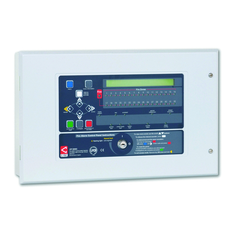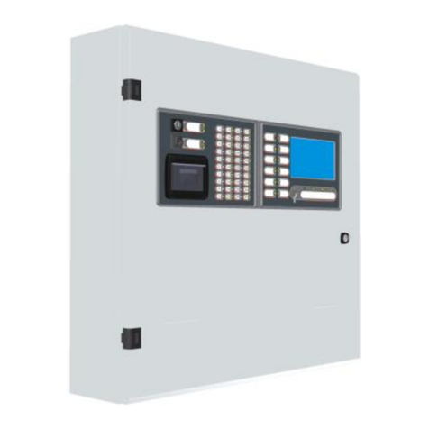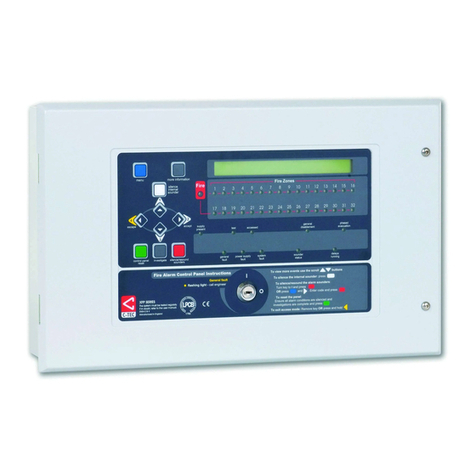
CAST ZFP - Quick Start Installation Guide
Approved Document No. DFU5030010 Rev 2 Page 1 of 2
WARNING! DO NOT connect or disconnect the panel’s internal wiring/looms, or terminate field wiring at the PCBs, with the panel’s power applied (either mains or battery).
Failure to observe this will destroy the panel’s electronic components and the warranty will be void.
ENSURE YOU HAVE ATTENDED C-TEC’S AUTHORISED TRAINING COURSE BEFORE ATTEMPTING TO INSTALL AND PROGRAM THE PANEL
THIS GUIDE IS FOR EXPERIENCED INSTALLERS OF ANALOGUE FIRE SYSTEMS ONLY AND SUMMARISES
KEY INFORMATION PROVIDED IN THE MAIN INSTALLATION AND PROGRAMMING MANUAL (DOCUMENT
NO.DFU5030000). IF YOU ARE IN ANY DOUBT WHATSOEVER,READ THE FULL MANUAL.
This product is a piece of Class 1 equipment and MUST BE EARTHED.
Anti-static handling guidelines: Make sure that handling precautions for electro-static devices (ESD) are
taken immediately before handling PCBs and other ESD components.
Section numbers, e.g. ,reference sections in the full manual with additional information.
EXTERNAL MAINS CONNECTION
Isolate mains power to the panel until it is ready to be tested (one method is to
open and lock off the main circuit breaker to the panel).
The panel is supplied with 230V, 50Hz mains. Terminate incoming mains to L
(Live), N (Neutral) and (Earth) terminals at CONN1 on the Power Supply
PCB, shown right.
RECOMMENDED CABLE TYPES
All cables must be installed in accordance with the relevant national, regional or local regulations.
Mains wiring is fixed wiring, using fire resistant, 3-core cable (no less than 1mm2and no more than 2.5mm2),
or a suitable three conductor system fed from an isolating switched fused spur, fused at 3A. Mains wiring should
be segregated from extra low voltage field wiring.
Extra low voltage field wiring includes loop circuits, conventional sounder circuits and auxiliary inputs/outputs.
Fire resistant, screened cable may be used such as FP 200™, Firetuff™, Firecel™ and MICC. All screens must be
terminated to the earth bar provided in the panel’s back box.
INTERNAL BATTERIES CONNECTION
Isolate battery power to the panel until it is ready to be tested (one method is to
disconnect the green battery link wire).
Fit two new, good quality and fully charged 12V VRLA batteries. Use the
connection wires (supplied) to connect the batteries to CONN7 on the Power Supply
PCB, shown right.
RECOMMENDED SHORTFORM INSTALLATION &COMMISSIONING PROCEDURE
Note: DO NOT connect mains or battery power to the panel until the installation is complete, i.e. panel PCBs
are fitted and field wiring has been tested and connected to the panel.
Remove the panel’s lid and chassis.
Fit the panel’s back box to a wall.
Connect field cables to the panel via glands and terminate all screens to the earth bar in the back box.
Test field cables and ensure they are fault-free, i.e. check continuity of cable runs (including screens).
Check the continuity on the negative (-ve) line of the device loop to ensure it is fault free.
Remove the small cable cover on the PSU and connect external mains cable to the panel (with mains
isolated) –SEE DETAIL 1, opposite. Refit the cover.
Connect the panel’s internal batteries (with battery supply isolated) –SEE DETAIL 2, opposite.
Refit the panel’s chassis and lid.
Connect analogue loop(s) wiring to the panel –SEE DETAIL 3, opposite.
Connect conventional sounder circuit(s) to the panel –SEE DETAIL 4, opposite.
Connect additional field wiring to the panel –SEE DETAIL 5, opposite.
Apply mains and battery supply to power up the panel.
Investigate and rectify any messages reported as faults on the panel’s touchscreen.
Commission the panel by entering AL3 and performing an auto address or loop learn (see overleaf).
Program the panel using the CAST ZFP Programming Tools (Part No. ZTOOLS).
TYPICAL ANALOGUE LOOPS CONNECTION
Two analogue loop connectors
(Loop1 & Loop2) areprovided on the
Main 2-Loop PCB, shown right.
Note:A1-LoopPCBisalsoavailable.
N.B. Some protocols and systems
have different methods of loop
isolation. The example shown right
has loop isolators in every +ve leg of each device. See full manual for details.
Terminate all screens to the earth bar in the panel’s back box.
CONVENTIONAL SOUNDER CIRCUITS CONNECTION
Two conventional sounder circuit
connectors (SNDR1 & SNDR2) are
provided on the Main 2-Loop PCB,
shown right.
Terminate all screens to the earth bar in
the panel’s back box.
ALWAYS make sure the two 6k8 EOL resistors (supplied) are fitted at the last sounder on each circuit. If a
sounder circuit is unused, you must still connect the resistor at the panel terminals.
ADDITIONAL FIELD WIRING
Auxiliary inputs AUX 24V output Relay outputs A-Bus (RS485)
Disclaimer: Errors and omissions excepted. No responsibility can be accepted by the manufacturer or distributors of this range of fire panels for any misinterpretation of an instruction or guidance note or for the compliance of the system as a whole. The manufacturer’s policy is one of continuous improvement and we reserve the right to make changes to product specifications at our discretion and without prior notice.
