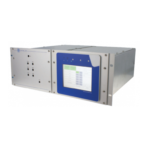
C-Tech HYLN-5 User manual

I
ROLLER COMPACTOR HYLN-5

I
CONTENTS
Preface ....................................................................................................................................................................1
Safety warning ........................................................................................................................................................1
I. Description ......................................................................................................................................................3
II. Main technical parameters ............................................................................................................................3
III. Main features and structure ..........................................................................................................................3
IV. Circuit and air circuit ......................................................................................................................................6
V. Test procedure ............................................................................................................................................. 10
VI. Software ....................................................................................................................................................... 12
VII. Installation and debugging .......................................................................................................................... 26
VIII. Maintenance, storage and transportation ................................................................................................. 30
Appendix 1 ........................................................................................................................................................... 33
Appendix 2 ........................................................................................................................................................... 34

- 1 -
Preface
Thank you very much for choosing this instrument.
This manual is specially used to guide users to use and maintain this instrument correctly.
Please keep this manual carefully, and put it in an easy-to-find place for reference at any time.
Before installing and using this instrument, you must read the manual carefully to ensure safe and
correct use of this instrument.
The company will not be responsible for damages or accidents caused by non-standard operation,
abnormal use environment, special use or modification without the company's consent, accidents,
force majeure, etc.
Safety warning
1. The instrument should be placed on a flat and firm platform to ensure that the supporting feet of
the instrument are completely in contact with the platform surface, and there is no corrosive gas,
electromagnetic interference source, strong air convection, etc. around.
2. Please read the instruction manual carefully before installing and using this instrument. If you
have any questions about the operation of the instrument or the documentation, please contact us.
3. Inconsistent with the installation, operation and maintenance procedures described in the
instruction manual may cause danger.
4. This instrument must be operated by specially trained personnel who are familiar with relevant
test methods and have been educated in instrument operation safety.
5. Before turning on the power, you must check whether the input power is consistent with the
requirements of the instrument, and ensure that the shell of the instrument is in a good grounding
state.
6. Knotting, squeezing, bending or folding the power cord is strictly prohibited; if the power cord is
damaged, stop using it immediately.
7. If an abnormal situation occurs, please turn off the power immediately and contact us in time.

-2 -
8. Please cut off the power supply when the instrument is not in use. When moving, maintaining, or
disassembling the instrument, the power supply must be cut off to ensure the safety of personnel
and the instrument.
9. Be careful when transporting the instrument. Sudden strong bumps or drops may cause damage
to the instrument.

- 3 -
I. Description
The HYLN-5 Roller compactor uses pneumatic loading and is suitable for making asphalt specimens
using hot mix asphalt mixtures and simulating the on-site conditions. The specimens can be used
for rutting test, sawn into beam shape for bending test, cut into column or cored for indirect tensile
and residual strain test. The thickness of the specimen can be set arbitrarily between 40 and 120
mm according to the needs of users.
II. Main technical parameters
Total power
1000W
Power supply
AC220V 50/60HZ
Maximum load
55KN
Trolley travel
±150mm
Cycle time
Variable, up to 10 cycles per minute
Specimen thickness
40~120mm (adjustable)
Vibrating frequency
0~50Hz (adjustable)
air compression
0.6~0.8MPa,700L/min
Mold size
300×300, 300×400, 305×300, 305×400 (optional)
Overall dimensions
1780×950×1550 mm
Weight
About 750 kg
III. Main features and structure
Main features
1. Adopt LCD touch screen. The operation interface is clear and visible, simple to set, and can display
the work process data in real time.
2. Use Japanese Panasonic inverter, which can change the vibration frequency arbitrarily between
0-50Hz.
3. Fan-shaped steel rollers.

- 4 -
4. The mold size of the roller compactor: 300×300mm, 300×400mm, 305×300mm, 305×400mm.
Mold thickness: 40-120 mm, can be made according to user requirements, suitable for the use of
the wheel tracking apparatus, and can automatically make specimen at one time according to the
preset height or density.
5. The maximum compaction load is 55KN, which is equivalent to the largest static roller on site.
6. Through the touch screen, the operator can set the loading pressure, vibration frequency and
round-trip times.
7. Simulate on-site vibration rolling, and the frequency can be adjusted.
8. Safety protection door. When any one of the three protective doors is opened, the equipment will
be cut off gas and power to protect the safety of the operator and prevent misoperation.
9. The specimens can be used for rutting test, sawn into beam shape for bending test, cut into
column or cored for indirect tensile and residual strain test.
10. Easy to insert and remove the mold.
Structure
Control panel
The equipment control panel (as shown in the figure) includes an LCD touch screen, a power indicator,
and an emergency stop switch.

- 5 -
Electrical cabinet control panel
[LCD touch screen]: Control the action of the instrument through the screen.
[Power indicator light]: When the instrument is powered on, the indicator light is on.
[Power switch]: Control the on and off of the power supply of the instrument. It is recommended to
turn off after cleaning the site.
Overall structure
This instrument is composed of a base, a trolley, a fan-shaped steel roller, a roller pressure and
specimen height adjustment system, a reciprocating motion system, a protection system, a vibrator,
and an electrical control cabinet. The operating system of the equipment is controlled by the stm32
LCD touch screen
Power indicator
Emergency stop

- 6 -
single-chip microcomputer, and the test mold is prepared according to the requirements of the user.
Roller compactor HYLN-5
IV. Circuit and air circuit
Circuit
Connect the power supply. The power supply required by the equipment is 220V AC. The yellow-green
wire is the ground wire. After connecting, use the meter to confirm the installation is correct.
WARNING!
The shell of the instrument must be grounded reliably, otherwise it is strictly
forbidden to turn it on!
The physical diagram of the circuit part is shown in the figure.

- 7 -
The physical diagram of the circuit part
The wiring schematic diagram of the circuit part is shown in the figure below.

- 8 -

- 9 -
Pressure sensor
Main valve
Physical diagram of the air circuit
Electric proportional
valve
Speed control
valve
Air circuit
The physical diagram of the air circuit part is shown in the figure below.

- 10 -
V. Test procedure
1. Connect the air source first, then the power source. Turn on the [emergency stop switch] to power
up the instrument (if there is no alarm sound, the instrument is operating normally).
2. The instrument automatically enters the [Startup] interface. Check whether the boxes in front of
"parameter download completed" and "the pressure correction table is download " are marked with
"√", as shown in Figure 6-1. If yes, it means that the instrument parameter download is normal, and
you can proceed to the next step. Otherwise, follow the steps below to download parameters:
①.Click the "Enter the Test" button to enter the [Test] interface (as shown in Figure 6-2);
②.Click the "Help & Settings" button to enter the [Help & Settings] interface (as shown in Figure
6-3);
③.Click the "Parameter Setting" button to enter the [Parameter Setting] interface (as shown in
Figure 6-4). Set the loading pressure, vibration frequency and round-trip times
corresponding to each test stage. Click the "Data Download" button, and then click the
"Return" button to return to the [Help & Settings] interface;

- 11 -
④.Click the "Pressure Correction Table" button to enter the [Pressure Correction Table]
interface (as shown in Figure 6-9). Set seven groups of corresponding control voltage,
feedback voltage and actual pressure, and click the "data download" button;
WARNING!
In order to use this instrument safely and correctly, please carefully read the
precautions displayed on the [Startup] interface.
3. In the [Test] interface, click the "Loading and Unloading" button to enter the [Loading and
Unloading Settings] interface (as shown in Figure 6-3). Click the "loading position" button to make
the mold trolley move to the left side of the equipment to facilitate the loading and unloading of the
mold.
4. Turn off the power, open the protective door on the left side of the equipment, and remove the
fixed roller for the mold. Put the loaded test mold on the trolley of the roller compactor, put the test
mold fixed roller to fix the test mold, and close the protective door. For specific methods, please refer
to the "Feeding Steps" in the [Help notes] interface (as shown in Figure 6-11);
5. After the loading is completed, in the [Loading and Unloading Settings] interface, click the
"intermediate position" button to make the test trolley reach the middle position. After the test trolley
is in place, click the "preloading stage" button, and the instrument enters the preloading stage;
NOTE
In this mode, the vibrating motor does not work, but uses this stage to make
the pressurized cylinder and the round-trip cylinder enter the working state,
preparing for the formal start of the test.
6. In the [Test] interface, click any stage from "P1 stage" to "P6 stage". After selection, the word of
the selected button turns red, and the instrument can start working according to the parameters of
the selected test stage.
7. The instrument will automatically jump to the next stage after finishing the work of this stage. If
the number of round trips in the next stage is set to 0, the next stage will be automatically skipped
and the test will continue. After the instrument completes to the last test stage in sequence, it will
stop automatically. Click the button of the current stage, that is, click the button with the word in red
can stop the test in advance.
8. For example, click “P1 Stage” to start the test, the word of “P1 Stage” button will turn to red and

- 12 -
the instrument will start to run according to the parameters set in P1 Stage. After the P1 Stage is
completed, the instrument will skip to the P2 Stage automatically, the word of “P2 Stage” will turn to
red and the instrument will start to run according to the parameters set in P2 Stage. In this way, the
instrument will automatically stop after the six test stage completed.
If the number of round trips of the P2 Stage is set to 0, the instrument will automatically skip the P2
stage and proceed to the P3 stage after completing the P1 stage.
If the P2 stage is in progress, click the "P2 stage" button can stop the test.
9. After the test process is completed and the instrument stops, in the [Loading and Unloading
Settings] interface, click the "Loading Position" button, and the mold trolley will move to the left side
of the instrument to facilitate the loading and unloading of the test mold. For specific methods,
please refer to the " Unloading Steps" in the [Help Notes] interface (as shown in Figure 6-11);
10. Turn off the emergency stop switch and disconnect the power supply of the instrument. Open the
protective door on the left, take off the fixed roller of the mold, and remove the rolled mold.
VI. Software
Startup interface
After the instrument is powered on, the LCD touch screen enters the [Startup] interface (as shown
in Figure 6-1);

- 13 -
Figure 6-1 Startup interface
Please read the "Matters needing attention" carefully and strictly abide by it;
View "Equipment Information". "Parameter download completed" and "correction table is
downloaded" mark "√" in the box in front, indicating that the parameter download is normal;
Click the "Enter the Test" button to enter the [Test] interface.
Test interface
In the [Startup] interface shown in Figure 6-1, click the "Enter the Test" button, and the instrument
will enter the [Test] interface, as shown in Figure 6-2. The parameters and buttons are explained as
follows.
[Test time]: Start timing when the test starts, and stop timing when the test stops;
[Gas source pressure (MPa)]: Display the total air pressure entering the equipment;
[Device status code]: The device status code indicates the current working status of the device or
the fault that has occurred. For specific content, please refer to the status code description in the
appendix, and you can also directly query it in the device help;
[Current pressure (kN)]: Display the real-time pressure of the current test stage;

- 14 -
[Set pressure (kN)]: Display the pressure value set in the current test stage, that is, the loading
pressure set in the [Parameter Setting] interface;
Figure 6-2 test interface
[Current roundtrip times]: Display the number of round trips to the current test stage;
[Set roundtrip times]: Display the total number of round trips set in the current test stage, that is, the
number of round trips set in the [Parameter Setting] interface;
[Vibration frequency]: Display the vibration frequency set in the current test stage, that is, the
vibration frequency set in the [Parameter Setting] interface;
[P1 stage]: Click the "P1 stage" button, start the test according to the parameters set in the P1 stage,
and proceed to the P6 stage in turn, and end. The parameters of this stage are the parameters of
the corresponding stage set in the [Parameter Setting] interface. P2~P6 is similar to P1.
[Clear the Alarm]: If the device currently has an alarm code, click this button to clear it. In the
[Description of device status code] interface or refer to Appendix 2 of this manual, you can view the
fault codes and their solutions (If the failure is not solved, the alarm sound and alarm code still exist).
[Help & Settings]: Click this button to jump to the [Help & Settings] interface.

- 15 -
NOTE
1. The font color of the button is red, indicating that this stage is currently
ongoing.
2. The vibration motor does not start during the preloading. This stage is only
the preparation stage before the start of the test. The purpose is to make the
fan-shaped steel roller and the test mold cooperate in advance to avoid loud
noise due to the loading pressure at the beginning of the test.
3. In P1~P6 stage, the vibration motor is normal and starts according to the
set vibration frequency.
Loading and unloading settings interface
In the [Test] interface shown in Figure 6-2, click the "Loading and Unloading" button, and the
instrument enters the [Loading and Unloading Settings] interface, as shown in Figure 6-3. The
parameters and buttons are explained as follows.
Figure 6-3 Loading and Unloading Settings Interface
[Loading position signal]: It indicates the loading position signal of the cylinder to and from the
cylinder. The green indicates that the cylinder is not at the loading position, and the red indicates
that the cylinder is at the loading position.

- 16 -
[Intermediate position signal]: indicates the intermediate position signal of the round-trip cylinder.
The green indicates that the cylinder is not in the intermediate position, and the red indicates that
the cylinder is in the intermediate position.
[Current pressure (kN)]: Display the real-time loading pressure;
[Loading position]: Click this button to move the round-trip cylinder, and stop when it reaches the
loading position, which is convenient for loading and unloading of test molds;
[Intermediate position]: Click this button, the round-trip cylinder will run to the middle position and
stop;
[Pressure head drop]: Click this button, the pressurize cylinder acts. The indenter will press down
according to the "loading pressure" set during the preloading stage. The content of the button
changes to red "Indenter up"; click the button again, the indenter rises;
[Preloading stage]: Click this button, the device will preload according to the parameters of the pre-
loading stage set in the [Parameter Setting] interface. Compared with the P1~P6 stages, the
vibration motor will not turn on at this stage.
[Reset]: Click this button to restore air source ventilation when the protective door is closed.
[Return]: Click this button to back to the [Test] interface.
Help & Settings interface
In the [Test] interface shown in Figure 6-2, click the "Help & Settings" button, the instrument enters
the [Help & Settings] interface, as shown in Figure 6-4, the description of each button is as follows:
[IO Testing]: Click this button to enter the [IO Testing] interface, as shown in Figure 6-5;
[Signal Testing]: Click this button to enter the [Signal Testing] interface, as shown in Figure 6-7;
[Parameter Setting]: Click this button to enter the [Parameter Setting] interface, as shown in Figure
6-8;
[Pressure Correction Table]: Click this button to enter the [Pressure Correction Table] interface, as
shown in Figure 6-9;

- 17 -
[Data Save & Recovery]: Click this button to enter the [Data Save & Recovery] interface, as shown in
Figure 6-10;
[Help notes]: Click this button to jump to the interface of [Help notes], as shown in Figure 6-11;
[Return]: Click this button to return to the [Test] interface.
Figure 6-4 Help & Settings interface
IO testing interface
In the [Help & Settings] interface shown in Figure 6-4, click the "IO Testing" button, and the
instrument will enter the [IO Testing] interface, as shown in Figure 6-5.
This interface is mainly used for instrument debugging. The word on the button turns red to indicate
that the corresponding action is being performed.
NOTE
This interface is mainly used for engineers to repair and test, and does not
need to be mastered by the customer.

- 18 -
Figure 6-5 IO testing interface
[JQ1], [JQ2], [JQ3], [JQ4], [JQ5], [JQ6], [JQ7], [JQ8]: Click the button, the font of the button will turn
red, and the corresponding light on the circuit board will light up. The corresponding lights of JQ1~JQ8
are M01~M08 on the circuit board, and their positions are shown in Figure 6-6.
[Round-trip cylinder alignment signal]: It indicates the mid-position signal of the round-trip cylinder.
Green indicates that the cylinder is not in the mid-position, and red indicates that the cylinder is in
the mid-position.
[Round-trip cylinder top signal]: It indicates the signal of the top position of the round-trip cylinder.
The green indicates that the cylinder is not at the top position, and the red indicates that the cylinder
is at the top position.
[Round-trip cylinder bottom signal]: It indicates the signal of the bottom position of the round-trip
cylinder. The green indicates that the cylinder is not at the bottom position, and the red indicates
that the cylinder is at the bottom position.
[Return]: Click this button to return to the [Help & Settings] interface.
Table of contents
