cabur DBC.2 User manual

TECHNICAL NOTE
N°
Page
Rev.
Date
Issue
d
Approved
31
1
4
18/07/14
DBC.2 “increased safety” terminal blocks, are manufactured according to the prescriptions given by
IEC / EN 60079-0, IEC / EN 60079-7 Standards and are in compliance with the ATEX 94/9/CE Directive and the IEC
Ex Certification Scheme
DBC.2 terminal blocks are also designed and manufactured in compliance with IEC / EN 60947-1 and IEC / EN 60947-7-1
reference product standards.
Terminal blocks (components) must be inserted in Ex e enclosures. The terminal blocks + enclosure assembly must
be subjected to separate certification.
DBC.2 terminal blocks are suited for a temperature range between - 40 and + 80 °C
Ambient temperature range shall be between - 40 and + 40 °C
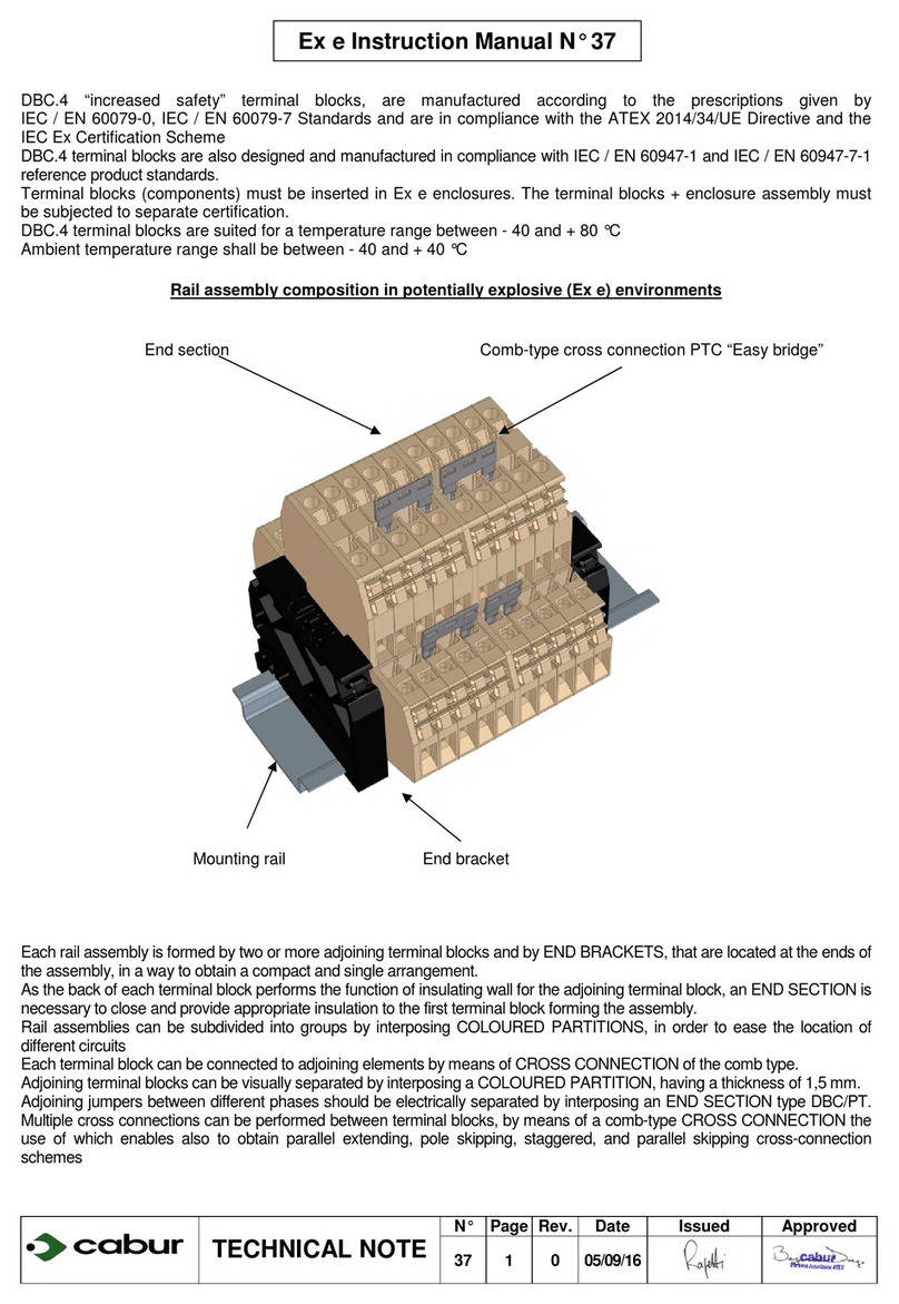
Rail assembly composition in potentially expolosive (Ex e) environments
End section Comb-type cross connection PTC “Easy bridge”
Mounting rail End bracket
Each rail assembly is formed by two or more adjoining terminal blocks and byEND BRACKETS, that are located at the ends of
the assembly, in a way to obtain a compact and single arrangement.
As the back of each terminal block performsthe function of insulating wall for the adjoining terminal block, an END SECTION is
necessaryto close and provide appropriate insulation to the first terminal block forming the assembly.
Rail assemblies can be subdivided into groups by interposing COLOURED PARTITIONS, in order to ease the location of
differentcircuits
Each terminal block can be connected to adjoining elements bymeans of CROSS CONNECTION of the comb type.
Adjoining terminalblocks can be visuallyseparated byinterposinga COLOURED PARTITION, having a thickness of 1,5 mm.
Adjoining jumpers between different phases should be electrically separated by interposing an END SECTION type DBC/PT.
Multiple cross connections can be performed between terminal blocks, by means of a comb-type CROSS CONNECTION the
use of which enables also to obtain parallel extending, pole skipping, staggered, and parallel skipping cross-connection
schemes
Ex e Instruction Manual N° 31

TECHNICAL NOTE
N°
Page
Rev.
Date
Issue
d
Approved
31
2
4
18/07/14
ATEX Marking:
0722 = number of the ATEX surveillance Notifying Body (CESI)
IM 2 = group I(mines), category M 2
II 2 = group II (surface), category 2
G = explosive atmosphere with presence of GAS
Ex e = “increased safety” protection mode
IIC= gas group
Gb = EPL
I= group I(mines)
Mb = EPL
DBC = terminal block series or type
2 = rated cross-section of terminal block
IEC Ex Marking Ex e IIC Gb Ex e IMb
Ex e = “increased safety” protection mode
IIC= gas group
Gb = EPL
I= group I(mines)
Mb = EPL
DBC.2 two-level feed-through terminal block - Rated Ex values
Terminal
block
Rated
cross
section
[
[[
[mm² ]
]]
]
Gauge
according
to
IEC
60947-1
Minimum /
maximum
flexible
conductor
[
[[
[mm² ]
]]
]
Rated
curren
t
[
[[
[A ]
]]
]
Resistance
of the
terminal
block
[
[[
[Ω
ΩΩ
Ω]
]]
](*)
Ex e
rated
voltage
[
[[
[Vac ]
]]
]
(**)
Test voltage
[
[[
[Vac ]
]]
]
DBC.2 2,5 A3 0,2 / 4 24 5,54 x 10
-4
400 2500
Notes: (*): values calculated from the results of the voltage drop test according to paragraph 8.4.4 of IEC 60947-7-1 Std.
(**): rated voltage values can be subjected to a + 10 % tolerance as listed in Table 1 of IEC 60079-7 Std.
“Easy bridge” PTC comb-type jumper - Jumper connection configurations
Sing
le orparallel
extending
Poleskipping
Adjacentwith
partition(**)
Staggeredmode
Parallel skipping
Ex eratedvoltage
(Vac)(*) Exerated voltage
(Vac)(*)
DBC.2 (upper level) 250 250 250 250 250
DBC.2 (lower level) 250 250 250 250 250
Notes: (*): rated voltage values can be subjected to a + 10 % tolerance as listed in Table 1 of IEC 60079-7 Std.
TERMINAL
BLOCK JUMPER
MULTIPLE
COMMONING BAR SCREW AND SLEEVE
C
URRENT OF THE JUMPER
[A]
DBC.2 PTC/2/… - - 21 / 24 (***)
Note (***):
the higher current value corresponds to the capacity embedding two jumpers for each one of the poles connected together
Instructions for the connection of PTC “Easy bridge” jumper.
After having cut the bar according to the number of poles, insert the cross-connection in the appropriate groove of the terminal block. At this point,
by using the blade of a screwdriver, push down the cross-connection until it reaches its blocking point. The cross-connection will be fully insulated
and intrinsically IPXXB protected. After having mounted the cross-connection the connected poles can be outlined and visually detected by placing
the PTC/SP green strip. This strip is supplied in a standard length of 100 mm and it can be easy cut to the appropriate length with the aid of a cutter.
To remove the cross-connection it is sufficient to remove the PTC/SP strip: insert the blade of the screwdriver in the jumper slot, then lift it up and
finally extract it.
0722
I
M 2
Ex e
I
Mb
II
2G
Ex e
II
C
Gb

TECHNICAL NOTE
N°
Page
Rev.
Date
Issue
d
Approved
31
3
4
18/07/14
Fig. A
Fig. B
POSITION COMPONENT
TERMINAL BLOCK
INSULATION
STRIPPING LENGTH
[ mm ]
TIGHTENING
TORQUE
[ Nm ] (*)
1 Insulating body DBC.2 9 0,4
2 Upper conducting body
3 Lower conducting body
4 Tightening screw
5 Wire clamping collar
Note(*): values taken from Table 4 of IEC 60947-1 Std.
Cabur terminal block type DBC.2 allows the direct and anti-loosening connection of solid, stranded and flexible conductors, by
means of wire clamping collars, captive screws and conducting body.
Each clamping unit shall house only one conductor
The insertion of the cable is eased by:
•Sloping entrance planes provided on the insulating body
•A tab provided in the collar that avoids faulty introduction of the conductors
•Adequate dimensioning of the conductors insertion hole, with respect to the diameter of the maximum connectable conductor
(according to the different Gauges prescribed by IEC 60947-1Std.)
Appropriate grooving, provided in the wire clamping collar and on the conducting body guarantee a perfect electrical contact and an
efficient blocking of the conductor. Both the wire clamping collar and the tightening screw are manufactured in tempered steel with
galvanic RoHS conforming zinc plating; thanks to their coupling it is possible to apply the correct contact pressure
By acting on the tightening screw, the collar tightens the conductor against the conducting body, which is manufactured in tin-plated
copper. With the clamping yoke tightening system a gas proof, particularly safe connection is guaranteed
Thanks to the force applied during the tightening process, the overlapped threaded parts system act,
by means of elastic deformation on the head of the screw, blocking it and avoiding subsequent
loosening
For the connection of the conductor it is necessary to:
1) Loosen the tightening screw (Pos.4 - Fig. A) until it frictions, making the collar (Pos.5 - Fig. A)
reach its lower position; once this operation is performed, the conductor’s insertion hole results
to be completely open and is ready to house the conductor.
2) Prepare the conductor by stripping one end from its insulation (Fig. B) and according to the
correct insulation stripping length given in the table. introduce it in the terminal block until the
limiting wall is reached. By holding firmly the conductor in one hand, tightening operation must be performed (applying the
prescribed torque values given in the table). Once this operation is performed the conductor is firmly secured.
Thanks to the force applied during the tightening process, the overlapped threaded parts system acts, by means of elastic
deformation on the head of the screw, blocking it and avoiding subsequent loosening
TECHNICAL NOTE
N°
Page
Rev.
Date
Issue
d
Approved
31
4
4
18/07/14
Attestation of Conformity to ATEX 94/9/EC Directive
Inserted in the following document: M19/e general instructions (leaflet inserted in every package)
Terminal blocks approved in conformity to ATEX 94/9/CE Directive
Terminal blocks “at increased safety” (Ex e) are manufactured according to IEC/EN 60079-0,
IEC/EN 60079-7 Std. and bear, on the insulating body, the name of the product and the electrical
characteristics.
ATEX Marking:
0722
I
M 2 Ex e
I
Mb
II
2G Ex e
IIC
Gb
0722 = number of Notifying Body (CESI) for the ATEX surveillance
I
M2 = group
I
(mines), category M2
II
2 G = group
II
(surface) category 2 G (gas)
Ex e = “increased safety” protection mode
II
C = gas group
Gb = EPL
I
= group
I
(mines)
Mb = EPL
V= rated voltage
The CE Marking indicates the Conformity to EU Low-voltage Directive 2006/95/EC
Terminal blocks must be installed in enclosures “at increased safety”; the enclosure / terminal blocks
assembly must be subjected to separate certification
Other cabur Terminal Block manuals
Popular Terminal Block manuals by other brands

National Instruments
National Instruments TB-2715 installation guide

National Instruments
National Instruments SCXI-1384K Assembly and installation guide

Festo
Festo CPV GE-CO2-8 Series Electronic manual

Worth Data
Worth Data 802 RF user manual

Siemens
Siemens 3VM91 0JC1 Series operating instructions

Beckhoff
Beckhoff EL33-00 Series Documentation