NI PXIe-4300 User manual

Artisan Technology Group is your source for quality
new and certied-used/pre-owned equipment
• FAST SHIPPING AND
DELIVERY
• TENS OF THOUSANDS OF
IN-STOCK ITEMS
• EQUIPMENT DEMOS
• HUNDREDS OF
MANUFACTURERS
SUPPORTED
• LEASING/MONTHLY
RENTALS
• ITAR CERTIFIED
SECURE ASSET SOLUTIONS
SERVICE CENTER REPAIRS
Experienced engineers and technicians on staff
at our full-service, in-house repair center
WE BUY USED EQUIPMENT
Sell your excess, underutilized, and idle used equipment
We also offer credit for buy-backs and trade-ins
www.artisantg.com/WeBuyEquipment
REMOTE INSPECTION
Remotely inspect equipment before purchasing with
our interactive website at www.instraview.com
LOOKING FOR MORE INFORMATION?
Visit us on the web at www.artisantg.com for more
information on price quotations, drivers, technical
specications, manuals, and documentation
Contact us: (888) 88-SOURCE | sales@artisantg.com | www.artisantg.com
SM
View
Instra

USER GUIDE AND TERMINAL BLOCK
SPECIFICATIONS
NI PXIe-4300 and TB-4300/B/C
8 Ch, 250 kS/s, 300 V Ch-Ch Isolated Analog Input Module
This document describes how to install, configure, and set up the NI PXIe-4300 with the
TB-4300/4300B/4300C (TB-4300/B/C) terminal block, connect signals, and verify that the
system is working properly. Current versions of NI documents are available at ni.com/
manuals.
The TB-4300/B/C terminal blocks are designed for use with the following module as specified:
NI PXIe-4300 ................................................... 10 V maximum voltage measurement range,
AI+ to AI-
TB-4300.................................................... 10 V maximum voltage measurement range,
AI+ to AI-
TB-4300B ................................................. 300 V maximum voltage measurement range,
AI+ to AI-
TB-4300C ................................................. 20 mA maximum current measurement range,
AI+ to AI-
Note The keying of these terminal blocks prevent them from connecting to other
modules that could be damaged by the voltage present on the terminal block.
However, you should only use these terminal blocks with their supported modules.
Caution Do not supply hazardous voltages (>30 Vrms/42.4 Vpk/60 VDC) to the
terminal block without the terminal block being connected to the NI PXIe-4300.
Contents
Electromagnetic Compatibility Guidelines .............................................................................. 2
What You Need to Get Started ................................................................................................. 3
Installation ................................................................................................................................ 3
Install the Software ........................................................................................................... 3
Unpack and Install the Module......................................................................................... 4
Connect the Signals .......................................................................................................... 5
Install the Terminal Block ................................................................................................ 8
Confirm NI PXIe-4300 Module Recognition................................................................... 9
Run Test Panels ................................................................................................................ 10
Take an NI-DAQmx Measurement .................................................................................. 11
Use Your NI PXIe-4300 in an Application ...................................................................... 11
Terminal Block Removal..........................................................................................................13
Artisan Technology Group - Quality Instrumentation ... Guaranteed | (888) 88-SOURCE | www.artisantg.com

2|ni.com |NI PXIe-4300 and TB-4300/B/C
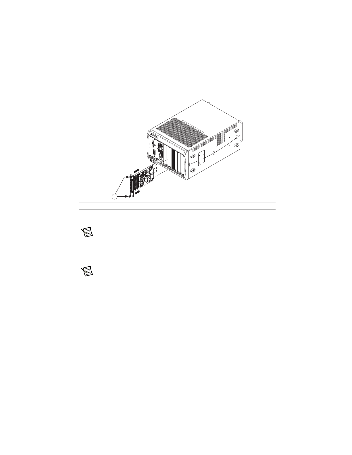
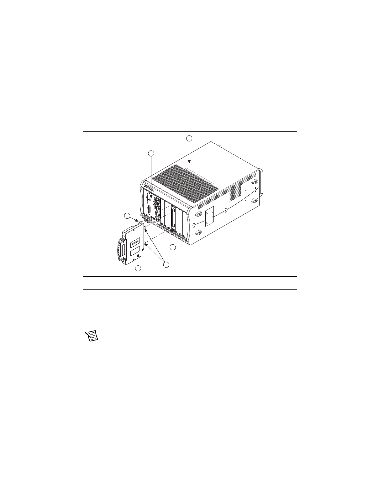
Module Removal.......................................................................................................................14
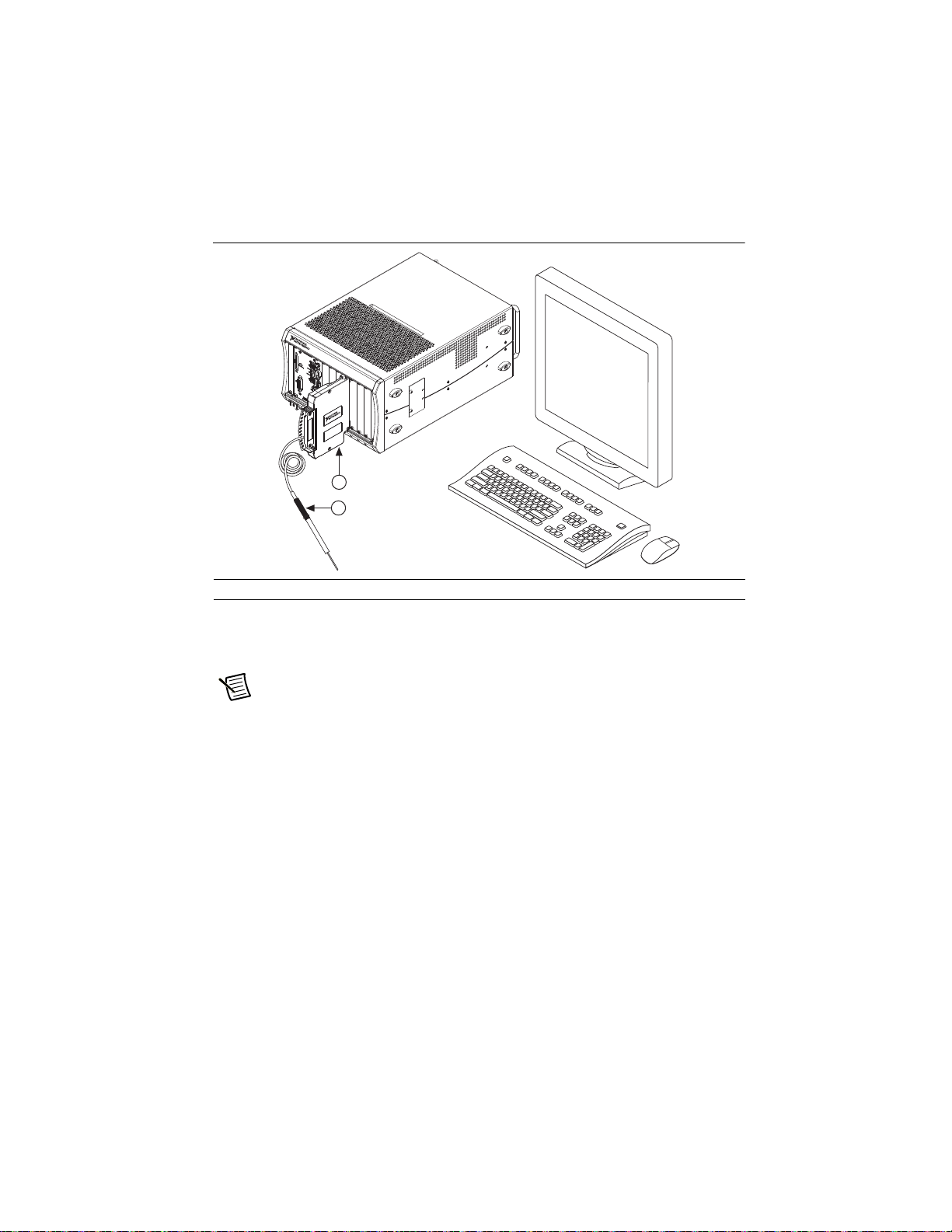
Create a Simulated Device........................................................................................................ 15
More Information...................................................................................................................... 16
Troubleshooting ................................................................................................................16
Specifications (TB-4300/B/C) .................................................................................................. 16
Calibration Interval ........................................................................................................... 16
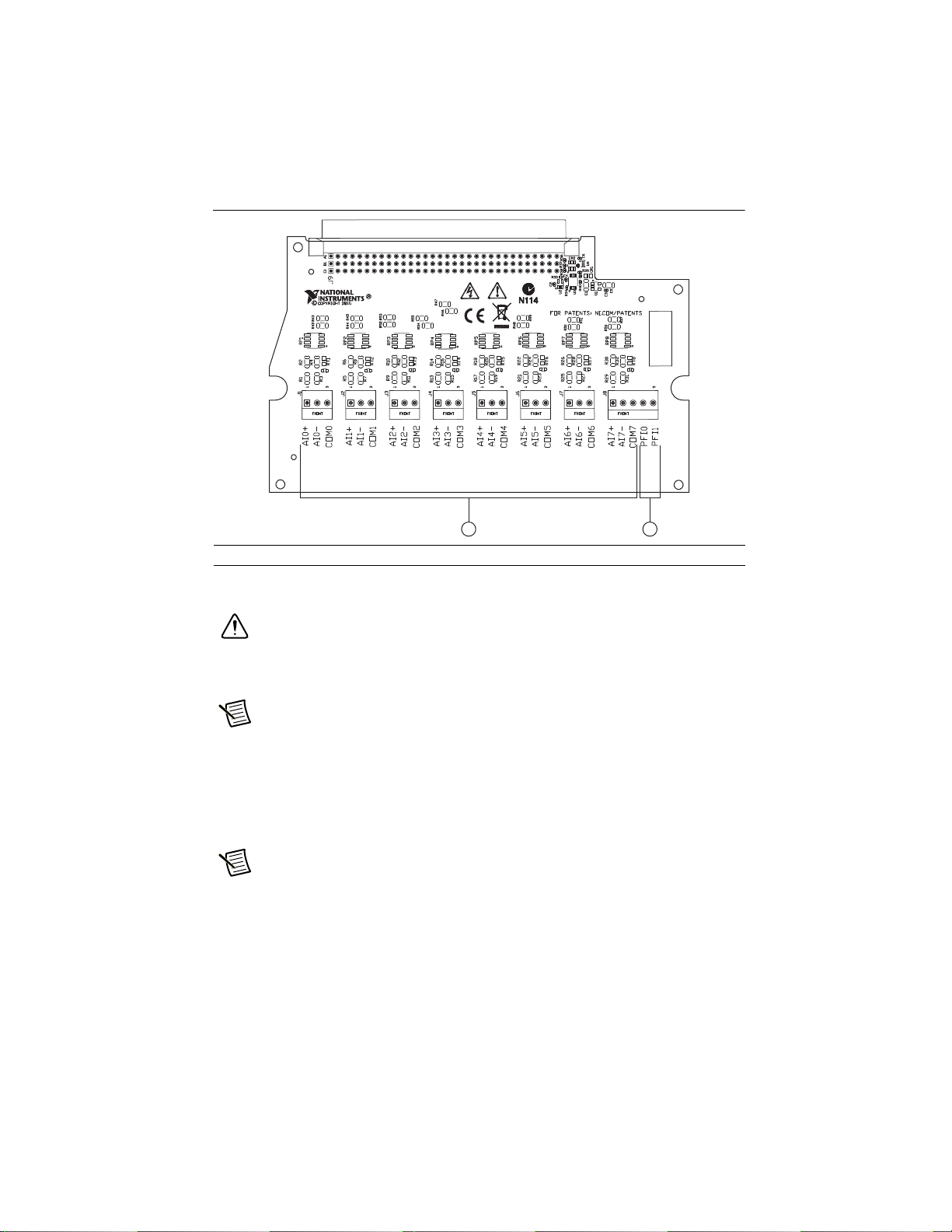
Electrical ...........................................................................................................................16
Mechanical........................................................................................................................ 17
Physical .............................................................................................................................17
Environmental Specifications ........................................................................................... 18
Shock and Vibration ......................................................................................................... 18
Safety Voltages .................................................................................................................19
Safety Standards ...............................................................................................................19
Electromagnetic Compatibility ......................................................................................... 19
CE Compliance ................................................................................................................. 20
Online Product Certification.............................................................................................20
Environmental Management............................................................................................. 20
Worldwide Support and Services .............................................................................................21
Electromagnetic Compatibility Guidelines
This product was tested and complies with the regulatory requirements and limits for
electromagnetic compatibility (EMC) stated in the product specifications. These requirements
and limits provide reasonable protection against harmful interference when the product is
operated in the intended operational electromagnetic environment.
This product is intended for use in industrial locations. However, harmful interference may
occur in some installations, when the product is connected to a peripheral device or test object,
or if the product is used in residential or commercial areas. To minimize interference with radio
and television reception and prevent unacceptable performance degradation, install and use this
product in strict accordance with the instructions in the product documentation.
Furthermore, any modifications to the product not expressly approved by National Instruments
could void your authority to operate it under your local regulatory rules.
Caution To ensure the specified EMC performance, operate this product only with
shielded cables and accessories.
Caution To ensure the specified EMC performance, the length of all I/O cables
must be no longer than 10 m (100 ft).
Artisan Technology Group - Quality Instrumentation ... Guaranteed | (888) 88-SOURCE | www.artisantg.com

NI PXIe-4300 and TB-4300/B/C |© National Instruments |3
What You Need to Get Started
To set up and use the NI PXIe-4300 module and TB-4300/B/C terminal block, you need the
following items:
Hardware
– NI PXIe-4300 module
– TB-4300/B/C terminal block
– NI PXIe chassis
– Cabling and sensors as required for your application
Tools
– Number 1 and 2 Phillips-head screwdrivers
– 1/8 in. flathead screwdriver
– Long-nose pliers
– Wire cutter
– Wire insulation stripper
Documentation
– Read Me First: Safety and Electromagnetic Compatibility
– NI PXIe-4300 and TB-4300/B/C User Guide and Terminal Block Specifications
– NI PXIe-4300 User Manual
– NI PXIe chassis user manual
You can download needed documents from ni.com/manuals.
Installation
Install the Software
Note You must be an administrator to install NI software and devices on your
computer.
Ensure the following software is installed before installing the NI PXIe-4300 and TB-4300/B/C
hardware:
1. Your application software, such as LabVIEW, LabWindows™/CVI™, or .NET.
2. NI-DAQmx—The PXIe-4300 module and TB-4300/B terminal blocks were first supported
in NI-DAQmx 9.1. The TB-4300C terminal block was first supported in NI-DAQmx 15.1.
Note For detailed NI software version support, refer to the NI-DAQmx Readme.
Back up any applications before upgrading software or modifying the application.
Artisan Technology Group - Quality Instrumentation ... Guaranteed | (888) 88-SOURCE | www.artisantg.com

4|ni.com |NI PXIe-4300 and TB-4300/B/C
Unpack and Install the Module
Remove the packaging and inspect the module. Contact NI if the module is damaged. Do not
install a damaged module.
Caution The module is static sensitive. Always properly ground yourself and the
equipment when handling or connecting to the module.
Complete the following steps to install the NI PXIe-4300 while referring to Figures 1 and 2:
Note To maintain forced air cooling in the PXIe system, refer to the Maintain
Forced-Air Cooling Note to Users.
1. Plug in your chassis before installing the NI PXIe-4300. The power cord grounds the
chassis and protects it from electrical damage while you install the module.
2. Make sure the chassis is powered off.
Caution To protect yourself, the chassis, and the NI PXIe-4300 from electrical
hazards, leave the chassis powered off until you finish installing the NI PXIe-4300
module.
3. Touch a metal part on the chassis to discharge any accumulated static electricity.
4. Identify a supported PXI Express slot in the chassis. NI PXIe-4300 modules can be placed
only in PXI Express Peripheral slots, PXI Express Hybrid Peripheral slots, and PXI Express
System Timing slots. Refer to the chassis documentation for details.
Figure 1. Symbols for PXI Express/PXI Express Hybrid/PXI Slots
5. Remove the filler panel, and touch any metal part of the chassis to discharge static
electricity.
6. Place the module edges into the module guides at the top and bottom of the slot.
Caution When installing the module, make sure both edges are positioned inside
the guides and that the module components do not come into contact with adjacent
modules.
7. Slide the module along the guides until it reaches the rear connector, then seat the module
by pushing the front panel until it is flush with the front panel of the chassis.
1 PXI Express System Controller Slot
2 PXI Peripheral Slot
3 PXI Express Hybrid Peripheral Slot
4 PXI Express System Timing Slot
NI PXIe-1062Q
1 2 34
Artisan Technology Group - Quality Instrumentation ... Guaranteed | (888) 88-SOURCE | www.artisantg.com

NI PXIe-4300 and TB-4300/B/C |© National Instruments |5
8. Secure the module to the chassis using the front-panel captive screws, shown in Figure 2.
Tighten the screws to 0.31 N·m (2.7 lb · in.).
Figure 2. Installing NI PXIe-4300 Modules
Connect the Signals
Note Refer to the Read Me First: Safety and Electromagnetic Compatibility before
removing equipment covers or connecting or disconnecting any signal wires.
To connect signals to the terminal block, refer to Figures 3 and 4 while completing the following
steps:
Note You can find the pinout names and locations in MAX at any time by
right-clicking the device name under Devices and Interfaces and selecting
Device Pinouts.
1. Loosen the captive top cover screws and remove the top cover.
2. Loosen the strain-relief screws and remove the strain-relief bar.
3. Prepare the signal wire by stripping the insulation no more than 7 mm (0.28 in.).
4. Run the signal wires through the strain-relief opening.
1CaptiveScrews
NI PXIe-1062Q
COOLING CLEARANCE AND FANFILTER MAINTENANCE REQUIRED. SEE MANUAL.
COOLING CLEARANCE AND FANFILTERMAINTENANCEREQUIRED.SEEMANUAL.
1
Artisan Technology Group - Quality Instrumentation ... Guaranteed | (888) 88-SOURCE | www.artisantg.com

6|ni.com |NI PXIe-4300 and TB-4300/B/C
Figure 3. TB-4300/B/C Parts Locator Diagram
5. Insert the stripped end of the signal wires fully into the appropriate terminal. Refer to the
label next to each screw terminal to determine the function of the terminal. The
NI PXIe-4300 User Manual provides more detailed wiring information. Make sure no
exposed wire extends past the screw terminal. Exposed wire increases the risk of a short
circuit that can cause circuit failure.
Note For accurate measurements, the COM terminal for the channel being used
must be connected to the ground of the AI source being measured. For the TB-4300C,
connect AI- to COM for the channel being used.
1 Strain-Relief Screws
2 Strain-Relief Bar
3 Tie Wrap Holes
4 Ground Lugs
5 Terminal Block to Module Connector
6 Captive Top Cover Screws
7 Top Cover
8 Tie Wraps
9 Signal Wires
1 2
1
6
7
6
4 5
9
4
3
8
Artisan Technology Group - Quality Instrumentation ... Guaranteed | (888) 88-SOURCE | www.artisantg.com

NI PXIe-4300 and TB-4300/B/C |© National Instruments |7
Figure 4. TB-4300/B/C Circuit Board Parts Locator Diagram
6. Tighten the terminal screws to a torque of 0.25 N·m(2.21lb·in.).
Caution Any wires connected to the ground must be sufficiently insulated from
high voltage.
7. Use the ground lugs to attach a shield wire to the ground.
Note Refer to the NI PXIe-4300 User Manual for details about shielding the
signals.
8. Reinstall the strain-relief bar and tighten the strain-relief screws.
9. Use tie wraps to connect the signal wires to the tie-wrap holes for additional strain relief
when necessary.
10. Reinstall the top cover and tighten the captive top cover screws.
Note For information about sensors, go to ni.com/sensors.
1 AI+, AI-, and COM Channels 2 Input PFI Channels
1 2
Artisan Technology Group - Quality Instrumentation ... Guaranteed | (888) 88-SOURCE | www.artisantg.com

8|ni.com |NI PXIe-4300 and TB-4300/B/C
Install the Terminal Block
Refer to Figure 5 to install the terminal block on the module while completing the following
steps:
1. Move the TB-4300/B/C into position in front of the NI PXIe-4300 and engage the
alignment feature with the guide on the associated module.
Figure 5. Installing the TB-4300/B/C on the NI PXIe-4300 Module
2. Attach the TB-4300/B/C to the NI PXIe-4300 module by pushing the terminal block
straight into the module. A spring mechanism will lock in the bottom of the terminal block.
3. Tighten the mounting screw at the top of the TB-4300/B/C to attach it to the NI PXIe-4300
module.
Note For safety purposes and to prevent damage to equipment when high voltages
are present, all NI PXIe-4300 modules and terminal blocks are keyed to prevent
connection between incompatible terminal blocks, modules, and/or cables.
4. Power on the chassis.
1 NI PXIe Controller
2 NI PXIe Chassis
3 Mounting Screw
4 TB-4300/B/C Terminal Block
5 NI PXIe-4300 Module
6 Alignment Feature
NI PXIe-1062Q
COOLINGCLEARANCEANDFANFILTERMAINTENANCE REQUIRED.SEEMANUA L.
COOLING CLEARANCE ANDFANFILTERMAINTENANCE REQUIRED.SEEMANUAL.
2
1
3
6
4
5
Artisan Technology Group - Quality Instrumentation ... Guaranteed | (888) 88-SOURCE | www.artisantg.com

NI PXIe-4300 and TB-4300/B/C |© National Instruments |9
Figure 6 shows an example NI PXIe-4300 system setup.
Figure 6. Sample NI PXIe-4300 System
Confirm NI PXIe-4300 Module Recognition
To confirm module recognition, complete the following steps:
Note Make sure you are using the most recent version of NI-DAQmx. If you are
using an older version of the driver software, the NI PXIe-4300 terminal block may
work only in basic functionality mode. Unsupported terminal blocks appear in
Measurement & Automation Explorer (MAX) with an X next to them.
1. Launch MAX.
2. Expand Devices and Interfaces, and expand NI-DAQmx Devices to confirm that MAX
detects the module and terminal block. The terminal block should appear beneath its
associated module. If your module or terminal block is not listed, press <F5> to refresh
MAX. If the module is still not recognized, go to ni.com/support/daqmx.
1 Terminal Block 2 Signal Input
NI PXIe-1062Q
COOLING CLEARANCEAND FAN FILTER MAINTENANCE REQUIRED.SEEMANUAL.
COOLING CLEARANCE AND FANFILTERMAINTENANCEREQUIRED.SEE MANUAL.
2
1
Artisan Technology Group - Quality Instrumentation ... Guaranteed | (888) 88-SOURCE | www.artisantg.com

10 |ni.com |NI PXIe-4300 and TB-4300/B/C
Tip Using an NI-DAQmx simulated device, you can test NI-DAQmx applications
without installing hardware. Refer to the Create a Simulated Device section for
instructions for creating NI-DAQmx simulated devices.
3. Right-click the module name and select Self-Test. When the self-test completes, a
verification message appears. If an error occurs, refer to ni.com/support/daqmx.
For information about sensors, go to ni.com/sensors.
Run Test Panels
1. In MAX, expand Devices and Interfaces, and select the chassis in which the module is
located.
2. Right-click the device, and select Test Panels.
Artisan Technology Group - Quality Instrumentation ... Guaranteed | (888) 88-SOURCE | www.artisantg.com

NI PXIe-4300 and TB-4300/B/C |© National Instruments |11
3. Click Start to test device functions, or Help for operating instructions.
To troubleshoot errors, refer to the NI-DAQmx Help, or go to ni.com/support.
Take an NI-DAQmx Measurement
NI-DAQmx Channels and Tasks
Refer to the NI-DAQmx Help for complete information about channels and tasks.
Use the DAQ Assistant to configure virtual channels and tasks in MAX or in your application.
Configure a Task Using the DAQ Assistant from MAX
Complete the following steps to create a task using the DAQ Assistant in MAX:
1. In MAX, right-click Data Neighborhood and select Create New to open the
DAQ Assistant.
2. Select NI-DAQmx Task and click Next.
3. Select Acquire Signals.
Note The NI PXIe-4300 cannot generate signals.
4. Select analog input, and the measurement type, such as voltage.
5. Select the physical channel(s) to use, and click Next.
6. Name the task and click Finish.
7. Configure the individual channel settings. Each physical channel you assign to a task
receives a virtual channel name. To modify the input range or other settings, select the
channel. Click Details for physical channel information. Configure the timing and
triggering for your task. Click Run.
Use Your NI PXIe-4300 in an Application
For NI software version compatibility, refer to the NI-DAQmx Readme, available from Start»
All Programs»National Instruments»NI-DAQmx.
To get started with data acquisition in your application software, refer to the tutorials listed in
Table 1.
Table 1. DAQ Assistant Tutorial Locations
Application Tutorial Location
LabVIEW Go to ni.com and search for Taking an NI-DAQmx
Measurement in LabVIEW.
LabWindows/CVI Go to Help»Contents. Next, go to Hardware Information»Data
Acquisition»Taking an NI-DAQmx Measurement in
LabWindows/CVI.
Artisan Technology Group - Quality Instrumentation ... Guaranteed | (888) 88-SOURCE | www.artisantg.com

12 |ni.com |NI PXIe-4300 and TB-4300/B/C
Programming Examples
NI-DAQmx includes example programs to help you get started developing an application.
LabVIEW and CVI examples are located at Help»Find Examples in your application software.
Text-based code examples are located at All Programs»National Instruments»NI-DAQmx»
Text-Based Code Support. Modify example code and save it in an application, or use examples
to develop a new application or add example code to an existing application.
For other examples, go to ni.com/info and enter the info code daqmxexp.
Measurement Studio From within the Visual Studio Documentation, go to
NI Measurement Studio Help»Developing Projects with
Measurement Studio»Getting Started with the Measurement
Studio Class Libraries»Measurement Studio Walkthroughs»
Walkthrough: Creating a Measurement Studio NI-DAQmx
Application.
NI SignalExpress*From the Getting Started screen, click General Help Topics. Next,
go to Using NI Hardware with SignalExpress»Taking an
NI-DAQmx Measurement in NI SignalExpress.
*NI SignalExpress, an easy-to-use configuration-based tool for data logging applications, is at Start»
All Programs»National Instruments»SignalExpress»NI SignalExpress.
Table 1. DAQ Assistant Tutorial Locations
Application Tutorial Location
Artisan Technology Group - Quality Instrumentation ... Guaranteed | (888) 88-SOURCE | www.artisantg.com

NI PXIe-4300 and TB-4300/B/C |© National Instruments |13
Terminal Block Removal
To remove the terminal block, refer to the appropriate figure while completing the following
steps:
Note Later TB-4300/B/C revisions include a latch release that you can use to
remove the terminal block from the module.
1. Power off chassis before removing the terminal block.
2. Loosen the terminal block captive screw located at the top of the terminal block.
3. Remove the terminal block according to the appropriate method:
Latch Release Method (refer to Figure 7)
a. Raise the latch release using a flathead screwdriver to disengage the latch.
b. With the latch release raised, grasp the terminal block and pull it away from the
module.
Figure 7. Removing the TB-4300/B/C from the NI PXIe-4300 Module (Latch Release)
1 Mounting Screw
2 Latch Release
3) NI PXIe Controller
4) NI PXIe Chassis
5 TB-4300/B/C Terminal Block
NI PXIe-1062Q
COOLING CLEARANCE AND FAN FILTER MAINTENANCE REQUIRED. SEEMANUAL.
COOLING CLEARANCEANDFANFILTER MAINTENANCEREQUIRED. SEE MANUAL.
4
5
3
1
2
Artisan Technology Group - Quality Instrumentation ... Guaranteed | (888) 88-SOURCE | www.artisantg.com

14 |ni.com |NI PXIe-4300 and TB-4300/B/C
Tilt-Down Method (refer to Figure 8)
a. Tilt the terminal block down and away from the module to disengage the guides.
b. Grasp the terminal block and pull it away from the module.
Figure 8. Removing the TB-4300/B/C from the NI PXIe-4300 Module (Tilt-Down)
4. Store the terminal block in an antistatic protective bag.
Module Removal
Caution Do not remove a module with the power on. Doing so can damage the
module.
To remove the module, refer to Figure 9 while completing the following steps:
Note To maintain forced air cooling in the PXIe system, refer to the Maintain
Forced-Air Cooling Note to Users.
1. Make sure that the chassis is powered off before removing the module.
2. Loosen the captive screws on the top and bottom of the module.
1 NI PXIe Controller
2 NI PXIe Chassis
3 TB-4300/B/C Terminal Block
4 Mounting Screw
NI PXIe-1062Q
COOLING CLEARANCE AND FAN FILTER MAINTENANCE REQUIRED. SEEMANUAL.
COOLING CLEARANCEANDFANFILTER MAINTENANCEREQUIRED. SEE MANUAL.
3
2
1
4
Artisan Technology Group - Quality Instrumentation ... Guaranteed | (888) 88-SOURCE | www.artisantg.com

NI PXIe-4300 and TB-4300/B/C |© National Instruments |15
Caution Do not pull the front panel to remove the module. Doing so may cause
module components to come into contact with adjacent modules, causing damage to
the modules.
3. Pull the captive screws to unseat the module and slowly slide the module along the guides.
4. Replace the filler panel in the empty slot.
5. Store the module in an antistatic protective bag.
Figure 9. Removing NI PXIe-4300 Modules
Create a Simulated Device
To run examples without the hardware installed, use an NI-DAQmx simulated device. To create
a simulated device in MAX:
1. Launch MAX.
2. Right-click Devices and Interfaces»Create New.
3. From the dialog, select Simulated NI-DAQmx Device or Modular Instrument.
4. Type 4300 in the text box at the top of the window.
5. Select the device from the list provided.
6. Click OK.
1 Captive Screws (Use to remove modules.) 2 Front Panel (Do not use to remove modules.)
NI PXIe-1062Q
COOLINGCLEARANCEAND FANFILTER MAINTENANCE REQUIRED.SEEMANUAL.
COOLINGCLEARANCE ANDFANFILTERMAINTENANCEREQUIRED.SEE MANUAL.
21
Artisan Technology Group - Quality Instrumentation ... Guaranteed | (888) 88-SOURCE | www.artisantg.com

16 |ni.com |NI PXIe-4300 and TB-4300/B/C
More Information
After you install NI-DAQmx, the NI-DAQmx documentation is available from Start»All
Programs»National Instruments»NI-DAQ. Additional resources are online at ni.com/
gettingstarted.
You can access online device documentation by right-clicking your module in MAX and
selecting Help»Online Device Documentation. A browser window opens to ni.com/
manuals with the results of a search for relevant documents. If you do not have web access,
documents for supported modules are included on the NI-DAQmx disc.
Troubleshooting
• Go to ni.com/support/install or ni.com/kb.
• If you need to return your National Instruments hardware for repair or device calibration,
go to ni.com/info and enter rdsenn to start the Return Merchandise Authorization
(RMA) process.
Specifications (TB-4300/B/C)
Note NI PXIe-4300 module specifications are located in the NI PXIe-4300
Specifications document.
All performance specifications are typical unless otherwise noted. These specifications are valid
within the full operating temperature range.
Calibration Interval
TB-4300 ............................................................No calibration
TB-4300B .........................................................1 year interval (verification only)
TB-4300C .........................................................No calibration
Electrical
TB-4300
Input impedance, device on ......................Feedthrough1
Input voltage range ...................................±1, 2, 5, 10 V
Fault voltage protection ............................60 V max
1 The TB-4300 is a feedthrough terminal block with no active circuitry. The input impedance registered is
the input impedance of the module to which it is attached.
Artisan Technology Group - Quality Instrumentation ... Guaranteed | (888) 88-SOURCE | www.artisantg.com

NI PXIe-4300 and TB-4300/B/C |© National Instruments |17
TB-4300B
Attenuation ratio ....................................... 30 to 1
Attenuator tolerance ................................. 0.05%
Attenuator temperature coefficient ........... 5 ppm/°C
Input impedance, device on ...................... 1.2 MΩ
Input voltage range ................................... ±30, 60, 150, 300 V
Fault voltage protection ............................ 300 V max
TB-4300C
Current sense resistor
Value ................................................. 50 Ω
Tolerance........................................... ±0.1%
Temperature coefficient .................... 15 ppm/°C
Input impedance, device on or off ............ 92 Ω
Input current range.................................... ±20 mA, 4 to 20 mA
Fault voltage protection ............................ 30 V max
Mechanical
Screw terminal wire gauge ............................... 1.31 mm2(16 AWG), max
Physical
Figure 10. TB-4300/B/C Dimensions
Weight............................................................... 618 g (21.8 oz)
Caution Clean the hardware with a soft, nonmetallic brush. Make sure that the
hardware is completely dry and free from contaminants before returning it to service.
5.10 in.
(12.95 cm)
6.02 in.
(15.28cm)
Artisan Technology Group - Quality Instrumentation ... Guaranteed | (888) 88-SOURCE | www.artisantg.com

18 |ni.com |NI PXIe-4300 and TB-4300/B/C
Environmental Specifications
Maximum altitude.............................................2,000 m (800 mbar), at 25 °C ambient
temperature
Pollution Degree ...............................................2
Indoor use only
Operating Environment
Ambient temperature range ..............................0 °C to 55 °C
(Tested in accordance with IEC 60068-2-1
and IEC 60068-2-2. Meets MIL-PRF-28800F
Class 3 low temperature limit and
MIL-PRF-28800F Class 2 high temperature
limit.)
Relative humidity range....................................10% to 90%, noncondensing
(Tested in accordance with IEC 60068-2-56.)
Storage Environment
Ambient temperature range ..............................-40 °C to 71 °C
(Tested in accordance with IEC 60068-2-1 and
IEC 60068-2-2. Meets MIL-PRF-28800F
Class 3 limits.)
Relative humidity range....................................5% to 95%, noncondensing
(Tested in accordance with IEC 60068-2-56.)
Shock and Vibration
Operating shock ................................................30 g peak, half-sine, 11 ms pulse
(Tested in accordance with IEC 60068-2-27.
Meets MIL-PRF-28800F Class 2 limits.)
Random vibration
Operating ..................................................5 Hz to 500 Hz, 0.3 grms
Non-operating ...........................................5 Hz to 500 Hz, 2.4 grms
(Tested in accordance with IEC 60068-2-64.
Non-operating test profile exceeds the
requirements of MIL-PRF-28800F, Class 3.)
Artisan Technology Group - Quality Instrumentation ... Guaranteed | (888) 88-SOURCE | www.artisantg.com

NI PXIe-4300 and TB-4300/B/C |© National Instruments |19
Safety Voltages
Maximum Input Voltage
Do not connect signals that are above the following limits. Doing so can result in damage to the
module.
AI+ to AI-
TB-4300.................................................... 60 V max
TB-4300B ................................................. 300 V max
TB-4300C ................................................. 30 V max
Isolation Voltages
Channel-to-channel........................................... 300 Vrms, Measurement Category II (Basic)
Channel-to-earth ground................................... 300 Vrms, Measurement Category II
Measurement Category II is for measurements performed on circuits directly connected to the
electrical distribution system. This category refers to local-level electrical distribution, such as
that provided by a standard wall outlet, for example, 115 V for U.S. or 230 V for Europe.
Caution Do not connect the TB-4300/B/C to signals or use for measurements
within Measurement Categories III or IV.
Caution The protection provided by the TB-4300 can be impaired if it is used in a
manner not described in this document.
Safety Standards
This product meets the requirements of the following standards of safety for electrical equipment
for measurement, control, and laboratory use:
• IEC 61010-1, EN 61010-1
• UL 61010-1, CSA 61010-1
Note For UL and other safety certifications, refer to the product label or the Online
Product Certification section.
Electromagnetic Compatibility
This product meets the requirements of the following EMC standards for electrical equipment
for measurement, control, and laboratory use:
• EN 61326-1 (IEC 61326-1): Class A emissions; Basic immunity
• EN 55011 (CISPR 11): Group 1, Class A emissions
• AS/NZS CISPR 11: Group 1, Class A emissions
• FCC 47 CFR Part 15B: Class A emissions
• ICES-001: Class A emissions
Artisan Technology Group - Quality Instrumentation ... Guaranteed | (888) 88-SOURCE | www.artisantg.com
This manual suits for next models
3
Table of contents
Other NI Terminal Block manuals
Popular Terminal Block manuals by other brands

National Instruments
National Instruments Terminal Block NI TB-2706 installation guide

aizo
aizo digitalSTROM GR-TKM200 Installation instructions for electricians

Festo
Festo VTSA-ASI 4E4A-Z Series manual

Crestron
Crestron CLT-1MC4 installation guide

Festo
Festo VIFB9-02 Series manual

Festo
Festo MPA-ASI-VI manual

National Instruments
National Instruments NI CB-37F-HVD installation guide

Scame
Scame ZENITH-P Installation, use and maintenance

Intelligent Appliance
Intelligent Appliance IA-2660-Ui user manual

Mitsubishi
Mitsubishi FX2N-16CCL-M Hardware manual

IOLINK
IOLINK SA-COM Series user guide

National Instruments
National Instruments TB-2627 installation instructions