4
Allgemeine Hinweise
Es gelten die Daten des allgemeinen bauaufsicht lichen
Prüfzeugnisses der Materialprüfanstalt MPA NRW,
D-59597 Erwitte. Prüfzeugnis-Nr. P-MPA-E-08-016 in
Verbindung mit gutachterlicher Stellungnahme.
Funktionserhaltkabel folgender Hersteller sind zugelas-
sen: Dätwyler, Eupen, Leoni Studer, Nexans, Prysmian.
Details siehe Prüfzeugnis.
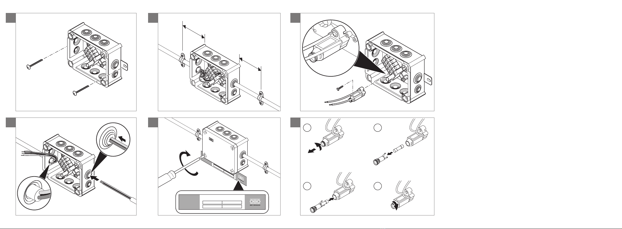
Hinweis zu den Abbildungen: Dargestellt sind beispiel-
haft die Typen T 100 ED 6-5, T 100 ED 6-5 A bzw.
T 100 ED 6-6 AF. Andere Typen können optisch abwei-
chen.
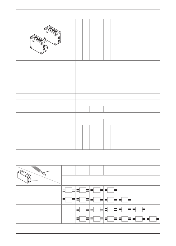
Lieferumfang
T... FireBox, vormontierte Anschlusseinheit,
2 Brandschutzschraubanker MMS 6x50,
2 Dichtungsscheiben.
T...A FireBox mit integrierter, vormontierter Anschlus-
seinheit.
T...F wie oben, mit Sicherungshalter Typ TE-FH 520
Benötigtes Zubehör
– Kennzeichnungsschild, Typ KS-E...
Für die Typen T...A empfehlen wir, OBO Brandschutz-
schraubanker MMS 6x50 zur Befestigung zu verwen-
den.