Montageanleitung Einspeiseblock ZLS924
Notice de montage Bloc d’alimentation ZLS924
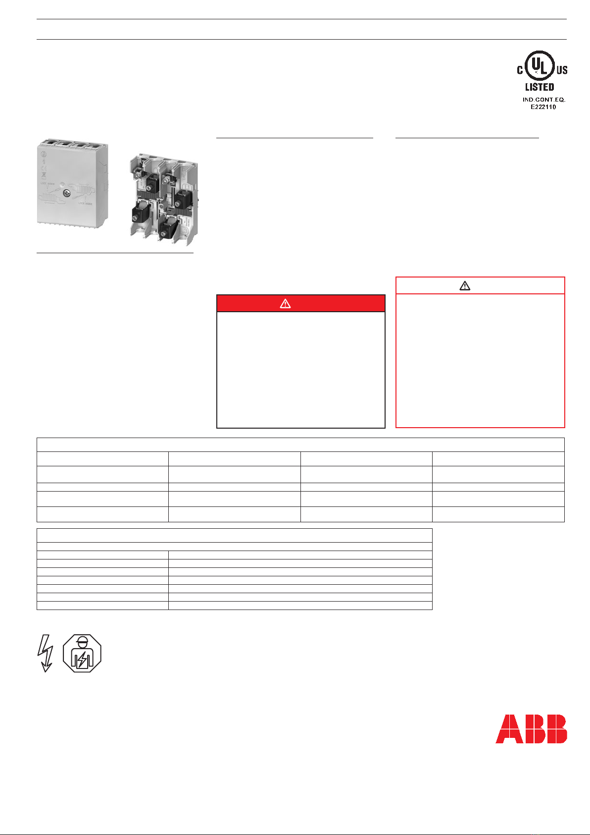
Mounting instruction Incoming Terminal Block ZLS924
2CCR181840B0001
May 2019
Warnung
Nichtbefolgung dieser Hinweise kann zu tödlichen Ver-
letzungen oder zu Sachschäden führen. Das Gerät darf
nur von einer elektrotechnisch unterwiesenen Person in-
stalliert werden. Vor Beginn der Installation ist die Netz-
spannungszufuhr abzuschalten.
Sicherheit
Es dürfen ausschliesslich die oberflächenveredelten
Sammelschienen von ABB verwendet werden. Am
Stecksockel-System dürfen keine Reparaturen vorge-
nommen werden.
Entsorgung
Defekte Geräte sind als Sondermüll an entsprechend
eingerichteten Sammelstellen zu entsorgen. Nationa-
le oder regionale Vorschriften über die Entsorgung von
Sondermüll sind zu befolgen.
Avertissement F
Le non-respect des présentes instructions peut
entraîner la mort, des blessures corporelles ou des
dégâts matériels. L’appareil doit uniquement être ins-
tallé par une personne qualifiée. Coupez l’alimentation
électrique principale avant de commencer l’installation.
Sécurité
Utiliser exclusivement les barres collectrices à surface
améliorée de ABB. Ne procéder à aucune sorte de répa-
ration sur le système de socle d’enfichage.
Elimination
Les appareils défectueux sont à éliminer en tant que
déchets spéciaux sur les lieux de collecte prévus à cet
effet. Respecter les prescriptions nationales ou régio-
nales.
Warning G
Failure to follow these instructions could result in death,
personal injury or property damage. The device should
be installed by a qualified person only. Turn off power
at the main power supply before beginning installation.
Safety
Only the surface-coated bus bars from ABB may be
used. Do not attempt to repair a damaged plug-in
socket system. Replace damaged components with
new components.
Disposal
Faulty products should be treated as hazardous waste
and disposed of in an appropriate manner. National or
regional regulations regarding the disposal of hazardous
waste should be adhered to.
Warning! Installation by person with electrotechnical expertise only.
Warnung! Installation nur durch elektrotechnische Fachkraft.
Avvertenza! Fare installare solo da un elettricista qualificato.
Avertissement! Installation uniquement par des personnes qualifiées en électrotechnique.
¡Advertencia! La instalación deberá ser realizada únicamente por electricistas especializados.
WARNING
HAZARD OF EQUIPMENT DAMAGE
• Use only material manufactured by ABB.
• Not following these instructions might result
in severe injuries or death or equipment
damage.
• This product is NOT suitable for use in
installation equipment any other than the
SMISSLINE SYSTEM.
• ABB doesn’t assume responsibility for any
consequences arising out of the use of this
equipment
WARNING
HAZARD OF ELECTRIC SHOCK, INJURY, BURN
OR EXPLOSION
• Make sure ALL electrical power supplies
are “OFF” before installing or removing any
devices or busbars.
• The Incoming Terminal block and compo-
nent MUST ONLY be installed and serviced
by QUALIFIED personnel.
• Always use properly rated voltage sensing
device to confirm the power is off.
• All devices, doors and covers must be
replaced before switching on the power to
this equipment
IEC data
Technische Daten FCaractéristiques techniques G Technical data
• Einspeiseblock: • Bloc d’alimentation standard: • Incoming Terminal Block, Standard:
Max. Bemessungsspannung: Tension nominale max.: Maximum Rated Voltage: 690 VAC
Max. Bemessungstrom: Intensité nominale max.: Maximum Rated Current: 160A
Hauptklemme: Borne principale: Main Terminal: 6 mm2up 50 mm22 x 25 mm2flexible wire with ferrules
Flat cable 9 x 2 x 0,8 up to 9 x 9 x 0,8 mm, Cu only
Hilfsklemme: Borne auxiliaire: Auxiliary terminal: 1,5 mm2up 10 mm2Stranded with ferrules
Cu only
UL data
For all types: Feeder Blocks cat. nos. ZLS924 are suitable for use in feeder circuits up to 250V
Rated Voltage: 600VAC
Rated Current (side feed, left or right): 150A
Short Circuit Protection: 150A Fuse or 250A Circuit-Breaker (DIVQ/7)
Torque: 4.0Nm (L,N); 1.5 Nm (LA, LB); 1.2Nm Cover screw
Stripping length: 18 mm (L,N); 11 mm (LA, LB)
Wire size: 10 AWG - 1/0 AWG, Cu only
Wire rated min. 600V and 75°C (AVLV2/8)


