Caen A3000NF Technical document

Technical
Information
Manual
MOD. A3000NF
3-PHASE NOTCH FILTER
MANUAL REV. 4
18 June 2008
Revision n. 4
NPO:
00120/04:3000N.MUTx/04

CAEN will repair or replace any product within the guarantee period if the Guarantor declares that the
product is defective due to workmanship or materials and has not been caused by mishandling,
negligence on behalf of the User, accident or any abnormal conditions or operations.
CAEN declines all responsibility for damages or
injuries caused by an improper use of the Modules due
to negligence on behalf of the User. It is strongly
recommended to read thoroughly the CAEN User's
Manual before any kind of operation.
This product must be installed by qualified personnel; the 3-phase EMC
filter Mod. CAEN A3000NF does not support operation in hostile areas
(magnetic field).
CAEN reserves the right to change partially or entirely the contents of this Manual at any time and without
giving any notice.
Disposal of the Product
The product must never be dumped in the Municipal Waste. Please check your local
regulations for disposal of electronics products.

Document type: Title: Revision date: Revision:
User's Manual (MUT) A3000NF 3Phase Notch Filter for A3486 18/06/2008 4
NPO: Filename: Number of pages: Page:
00120/04:3000N.MUTx/04 A3000NF_REV4.DOC 13 3
TABLE OF CONTENTS
1. A3000NF 3 PHASE NOTCH FILTER FOR A A3486...............................................................................5
1.1 OVERVIEW ...............................................................................................................................................5
1.2 TECHNICAL DESCRIPTION.........................................................................................................................5
1.3 REAR PANEL COMPONENTS.......................................................................................................................5
1.4 CHANNEL CHARACTERISTIC TABLE .........................................................................................................6
1.5 OUT CONNECTOR....................................................................................................................................6
1.6 IN CONNECTOR........................................................................................................................................7
1.7 CHASSIS EARTH .....................................................................................................................................7
1.8 FUSES.......................................................................................................................................................8
1.9 ELECTRICAL SCHEME ...............................................................................................................................8
2. SAFETY INFORMATION AND INSTALLATION REQUIREMENTS................................................9
2.1 INJURY PRECAUTIONS ..............................................................................................................................9
2.1.1 General Recommendations..............................................................................................................................9
2.1.2 Caution............................................................................................................................................................9
2.1.3 Grounding......................................................................................................................................................10
2.1.4 Input ratings ..................................................................................................................................................10
2.1.5 Live circuits...................................................................................................................................................11
2.1.6 Parts substitutions and modifications............................................................................................................11
2.2 INSTALLATION........................................................................................................................................11
2.2.1 Preparation for use........................................................................................................................................11
2.2.2 Initial inspection............................................................................................................................................11
2.2.3 Rack mounting...............................................................................................................................................11
2.2.4 AC source ......................................................................................................................................................12
2.2.5 3-phase power supply cable..........................................................................................................................12
2.2.6 Cooling Fans.................................................................................................................................................13
2.3 MAINTENANCE.......................................................................................................................................13
LIST OF FIGURES
FIG.1.1 –A3000NF REAR PANEL ............................................................................................................................5
FIG.1.2 –BACK PANEL LABEL.................................................................................................................................5
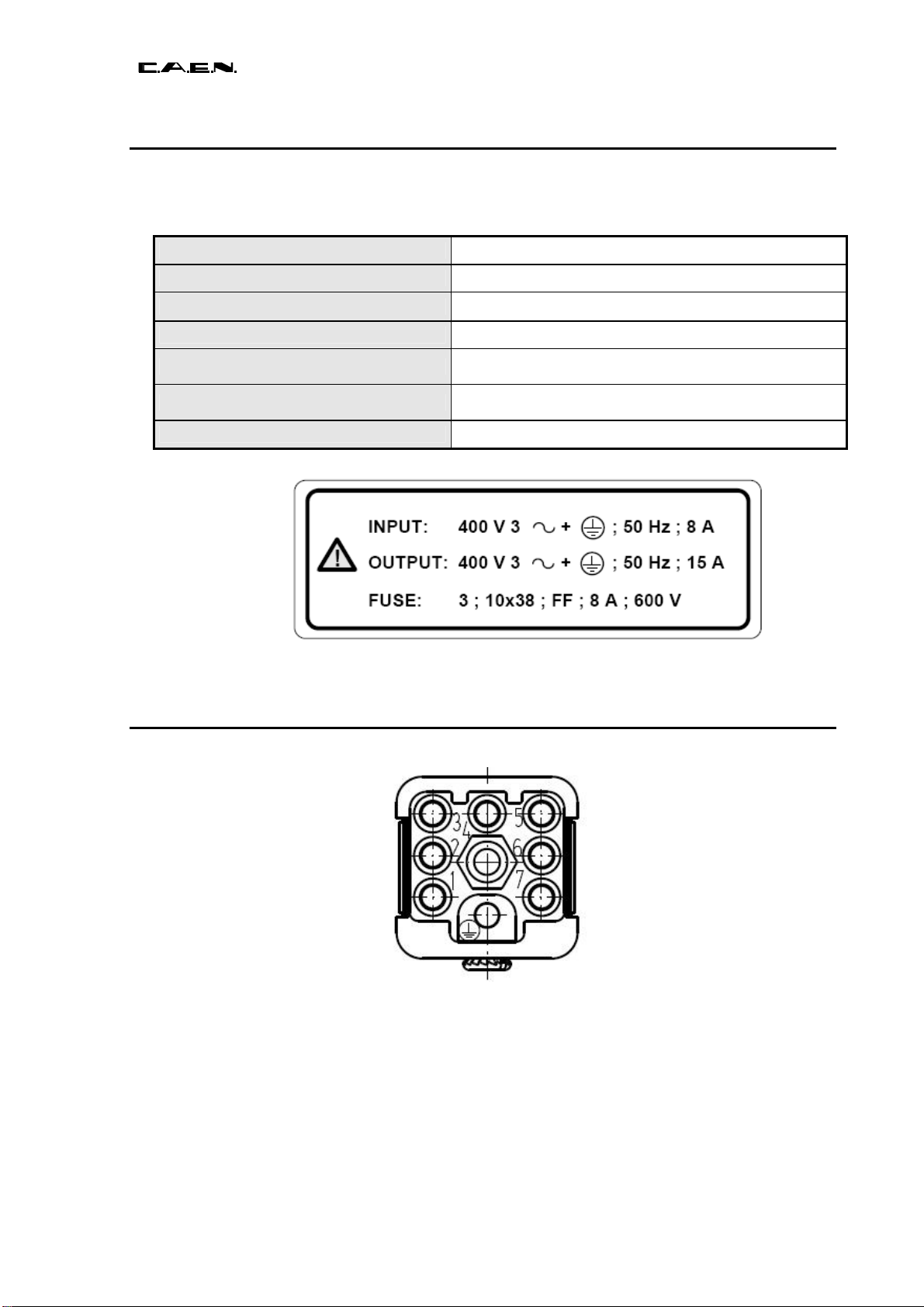
FIG.1.3 –AC I/O LABEL..........................................................................................................................................6
FIG.1.4 –HARTING FEMALE CONNECTOR ................................................................................................................6
FIG.1.5 –HARTING MALE CONNECTOR ....................................................................................................................7

Document type: Title: Revision date: Revision:
User's Manual (MUT) A3000NF 3Phase Notch Filter for A3486 18/06/2008 4
NPO: Filename: Number of pages: Page:
00120/04:3000N.MUTx/04 A3000NF_REV4.DOC 13 4
FIG.1.6 –EARTH CONNECTOR..................................................................................................................................7
FIG.1.7 –FUSE HOUSING ..........................................................................................................................................8
FIG.1.8 –MOD.A3000NF ELECTRICAL SCHEME.....................................................................................................8
FIG.2.1 –AC SOURCE CONNECTION.......................................................................................................................11
FIG.2.2 –POWER SUPPLY CONNECTOR AND CABLE................................................................................................13
LIST OF TABLES
TABLE 1.1 –TECHNICAL SPECIFICATIONS OF THE A3000NF 3PHASE NOTCH FILTER..............................................6

Document type: Title: Revision date: Revision:
User's Manual (MUT) A3000NF 3Phase Notch Filter for A3486 18/06/2008 4
NPO: Filename: Number of pages: Page:
00120/04:3000N.MUTx/04 A3000NF_REV4.DOC 13 5
1. A3000NF 3 Phase Notch Filter for a A3486
1.1 Overview
The CAEN Mod. A3486, in order to be CE compliant (CEI EN 61000-3-2 norm on
harmonic current emissions), requires 3-phase EMC filter Mod. CAEN A3000NF on the
mains supply cable; this filter does not support operation in hostile areas (magnetic field).
1.2 Technical description
The CAEN Mod. A3000NF is a two channel notch filter which must be used with the
A3486 3-Phase 220/400 Vac – 48 Vdc converter. I/O connectors are housed on the
module rear panel. The Mod. A3000NF can be used also on CAEN Mod. A3484, A3485,
A3485A and A3485B 400 Vac – 48 Vdc converters; for this purpose it is necessary to
install on such modules a Harting 09.12.007.3001 connector on the Mains power supply
cable (see § 2.2.5).
1.3 Rear panel components
Fig. 1.1 – A3000NF Rear panel
Fig. 1.2 – Back Panel Label

Document type: Title: Revision date: Revision:
User's Manual (MUT) A3000NF 3Phase Notch Filter for A3486 18/06/2008 4
NPO: Filename: Number of pages: Page:
00120/04:3000N.MUTx/04 A3000NF_REV4.DOC 13 6
1.4 Channel Characteristic Table
Table 1.1 – Technical specifications of the A3000NF 3 Phase Notch Filter
Packaging 19"-wide, 3U-high Euro-mechanics rack; Depth: 50 cm.
Weight 32 Kg
AC input 3-phase 400 V ±10% / 50 Hz (see label below)
AC output 3-phase 400 V / 50 Hz (see label below)
Max. Output Power 5000 W per section
Max. Input Power 5000 W per section
Fuses OMEGA type 10X38 8A 600V FF139280 (3 per channel)
Fig. 1.3 – AC I/O Label
1.5 OUT Connector
Fig. 1.4 – Harting female connector
Type: Harting 09 12 007 3101; Female insert, Han Q 7/0 Series Han Q;
Loading Pin: 09.15.000.6201
Pin: Phase:
1, 2 R
3, 4 S
5, 6 T
7 n.c.

Document type: Title: Revision date: Revision:
User's Manual (MUT) A3000NF 3Phase Notch Filter for A3486 18/06/2008 4
NPO: Filename: Number of pages: Page:
00120/04:3000N.MUTx/04 A3000NF_REV4.DOC 13 7
1.6 IN Connector
Fig. 1.5 – Harting male connector
Type: Harting 09 12 007 3001; Male insert, Han Q 7/0 Series Han Q;
Loading Pin 09.15.000.6106
Pin: Phase:
1, 2 R
3, 4 S
5, 6 T
7 n.c.
1.7 Chassis EARTH
Fig. 1.6 – Earth connector
This section provides the Earth auxiliary reference and includes:
1 Earth RADIALL R921921 type connector
WARNING: ALTHOUGH THE CHASSIS IS ALREADY INTERNALLY
CONNECTED TO PROTECTION EARTH PROVIDED BY MAINS POWER SUPPLY
PLUG, CAEN STRONGLY ADVICES TO CONNECT THIS TERMINAL TO A GOOD
EARTH WITH A LOW IMPEDANCE CABLE PATH, IN ORDER TO IMPROVE EMI
SHIELDING AND SAFETY.
THIS TERMINAL IS IN ITS TURN INTERNALLY CONNECTED TO PROTECTION
EARTH.

Document type: Title: Revision date: Revision:
User's Manual (MUT) A3000NF 3Phase Notch Filter for A3486 18/06/2008 4
NPO: Filename: Number of pages: Page:
00120/04:3000N.MUTx/04 A3000NF_REV4.DOC 13 8
1.8 Fuses
Fig. 1.7 –Fuse housing
Type: OMEGA type 10X38 8A 600V FF139280
3 Fuses per channel (one per phase)
1.9 Electrical scheme
Fig. 1.8 – Mod. A3000NF Electrical scheme

Document type: Title: Revision date: Revision:
User's Manual (MUT) A3000NF 3Phase Notch Filter for A3486 18/06/2008 4
NPO: Filename: Number of pages: Page:
00120/04:3000N.MUTx/04 A3000NF_REV4.DOC 13 9
2. Safety information and installation requirements
2.1 Injury Precautions
Review the following precautions to avoid injury and prevent damage to this product or
any products connected to it. To avoid potential hazards, use the product only as
specified. Only qualified personnel should perform service procedures.
2.1.1 General Recommendations
The A3000NF is provided with front panel fixing holes for 19" rack-mounting and will
occupy 3U of rack space. Rear support should be provided when fitted in a 19" rack.
The A3000NF is a heavy unit (32kg) and should be regarded as a two-man lift. Take
suitable precautions when lifting.
When rack-mounting the unit needs natural convection of air over the case and an
unrestricted air flow through the unit. The A3000NF will operate as a free-standing unit
without requiring any special cooling arrangement, but should not be allowed to be
accidentally or deliberately covered over in any way. Do not operate the unit with the top
cover removed as this exposes hazardous voltages.
WARNING: THE A3000NF ACTUALLY OBSTRUCTS THE VERTICAL AIR
FLOW THROUGH THE RACK!
2.1.2 Caution
The following safety precaution must be observed during all phases of operation, service
and repair of this equipment. Failure to comply with the safety precautions or warnings in
this document violates safety standards of design, manufacture and intended use of this
equipment and may impair the built-in protections within.
CAEN shall not be liable for user’s failure to comply with these requirements.
To avoid electric shock or fire hazard, do not apply a voltage to a load that is outside the
range specified for that load.
To avoid electric shock or fire hazard, do not operate this product with covers or panels
removed.
Do Not Operate Without Covers.
To avoid electric shock or fire hazard, do not operate this product with covers or panels
removed.
Do Not Operate in Wet/Damp Conditions.
To avoid electric shock, do not operate this product in wet or damp conditions.
Do Not Operate in an Explosive Atmosphere.
To avoid injury or fire hazard, do not operate this product in an explosive atmosphere.
Do Not Operate With Suspected Failures.
If you suspect there is damage to this product, have it inspected by qualified service
personnel.
WARNING: ALL ENCLOSED ELECTRICAL/ELECTRONIC EQUIPMENT
SHALL BE PROVIDED WITH A MEANS FOR DISCONNECTING IT FROM EACH

Document type: Title: Revision date: Revision:
User's Manual (MUT) A3000NF 3Phase Notch Filter for A3486 18/06/2008 4
NPO: Filename: Number of pages: Page:
00120/04:3000N.MUTx/04 A3000NF_REV4.DOC 13 10
EXTERNAL OR INTERNAL OPERATING ENERGY SOURCE. THIS DISCONNECTING
MEANS SHALL DISCONNECT ALL CURRENT CARRYING CONDUCTORS.
WARNING: DO NOT TOP LOAD
WARNING: IN ORDER TO PREVENT RISK OF ELECTRIC SHOCK OR FIRE
HAZARD DUE TO OVERHEATING, ENSURE THAT THE UNIT’S VENTILATION
OPENINGS ARE NOT OBSTRUCTED.
2.1.3 Grounding
This product is a Safety Class 1 instrument. To minimize shock hazard, the instrument
chassis must be connected to an electrical ground. The instrument must be connected to
the AC power supply mains through a three conductor power cable, with the ground wire
firmly connected to an electrical ground (safety ground) at the power outlet.
For instruments designed to be hard-wired to the supply mains, the protective earth
terminal must be connected to the safety electrical ground before another connection is
made. Any interruption of the protective ground conductor or disconnection of the
protective earth terminal will cause a potential shock hazard that might cause personal
injury.
WARNING: DUE TO THE HIGH LEAKAGE CURRENT, REMEMBER TO
CONNECT ALSO THE CHASSIS EARTH TERMINAL (SEE §1.7) TO A GOOD EARTH
WITH A LOW IMPEDANCE CABLE PATH, IN ORDER TO IMPROVE SAFETY; SUCH
TERMINAL IS IN ITS TURN INTERNALLY CONNECTED TO PROTECTION EARTH.
2.1.4 Input ratings
Do not use AC supply, which exceeds the input voltage and frequency rating of this
instrument. For input voltage and frequency rating of the module see § 1.4. For safety
reasons, the mains supply voltage fluctuations should not exceed above voltage range.

Document type: Title: Revision date: Revision:
User's Manual (MUT) A3000NF 3Phase Notch Filter for A3486 18/06/2008 4
NPO: Filename: Number of pages: Page:
00120/04:3000N.MUTx/04 A3000NF_REV4.DOC 13 11
2.1.5 Live circuits
Operating personnel must not remove the instrument cover. No internal adjustment or
component replacement is allowed by non-CAEN personnel. Never replace components
with power cable connected. To avoid injuries, always disconnect power, discharge
circuits and remove external voltage source before touching components (wait 15 min at
least).
2.1.6 Parts substitutions and modifications
Parts substitutions and modifications are allowed by authorized CAEN service personnel
only.
2.2 Installation
This Chapter contains instructions for initial inspection, preparation for use and
repackaging for shipment.
2.2.1 Preparation for use
In order to be operational the unit must be connected to an appropriate AC source. The
AC source voltage should be within the unit specification. The A3000NF shall be
connected to the AC source in the following way.
Fig. 2.1 – AC source connection
2.2.2 Initial inspection
Prior to shipment this unit was inspected and found free of mechanical or electrical
defects.
Upon unpacking of the unit, inspect for any damage, which may have occurred in transit.
The inspection should confirm that there is no exterior damage to the unit such as broken
knobs or connectors and that the front panel and meters face are not scratched or
cracked. Keep all packing material until the inspection has been completed. If damage is
detected, file a claim with carrier immediately and notify CAEN service.
2.2.3 Rack mounting
The Mod. A3000NF is an equipment for BUILDING-IN: it must be installed in a 19”
equipment rack and operated with its upper grid unloaded.
Use the front panel rack-mount brackets to install the unit in the rack.
This product must be installed by qualified personnel; EMC filter
Mod. CAEN A3000NF does not support operation in hostile areas
(magnetic field).

Document type: Title: Revision date: Revision:
User's Manual (MUT) A3000NF 3Phase Notch Filter for A3486 18/06/2008 4
NPO: Filename: Number of pages: Page:
00120/04:3000N.MUTx/04 A3000NF_REV4.DOC 13 12
WARNING: IN ORDER TO PROVIDE PROPER AIR FLOW, REMEMBER TO
LEAVE A ~1” (2.54cm) AT LEAST FREE SPACE ABOVE THE MODULE’S UPPER
PANEL, WHEN MOUNTED IN THE RACK.
2.2.4 AC source
The Mod. A3000NF ACsource is as follows:
The input voltage range and current required is specified in § 1.4. Ensure that under
heavy load, the AC voltage supplied to the unit does not fall below the specifications
described in § 1.4.
2.2.5 3-phase power supply cable
The power supply cable to be connected to the IN connector (see § 1.6) is configured as
follows (see also figure):
EARTH : green-yellow cable
L1: black cables N°1 & N°2
L2: black cables N°3 & N°4
L3: black cables N°5 & N°6
Connector type: Harting 09.12.007.3101
Hood: Harting 19.20.003.1440
Contacts: Harting 09.15.000.6201
Coding pin Female: Harting 09.12.000.9902
Cable: 113408 LTZE-Superfelx PLUS-N-PUR suitable to 15A@400V

Document type: Title: Revision date: Revision:
User's Manual (MUT) A3000NF 3Phase Notch Filter for A3486 18/06/2008 4
NPO: Filename: Number of pages: Page:
00120/04:3000N.MUTx/04 A3000NF_REV4.DOC 13 13
Fig. 2.2 – Power supply connector and cable
2.2.6 Cooling Fans
WARNING: INTERNAL FANS ARE POWERED ONLY BY THE LEFT
TRIPHASE INPUT, THEREFORE FOR COOLING PURPOSES, IT IS IMPORTANT
THAT, WHENEVER ONLY ONE CHANNEL OF THE A3000NF IS USED, THAT HAS
TO BE THE LEFTMOST (FROM REAR PANEL VIEW, SEE § 1.3).
2.3 Maintenance
No routine maintenance of the unit is required except for periodic cleaning. To clean,
disconnect the unit from the AC supply and allow 15 minutes for discharging. The metal
surfaces should be cleaned using a damp soft cloth containing a mild solution of
detergent and water. Use low pressure compressed air to blow dust from the unit.
The Protective Earth Ground must be connected
before applying AC Power to the unit
Table of contents
Popular Water Filtration System manuals by other brands

Durr Dental
Durr Dental Hygopure 90 Installation and operating instructions

Ekobrew
Ekobrew Ekobrew instructions

Sera
Sera fil bioactive 130+UV instructions

Angelo Decor
Angelo Decor Pond Building Filter Box 600 quick start guide

Water Depot
Water Depot Blaster Soft owner's manual

BWT
BWT RTM CT T-500 Installation and operating instructions