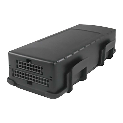
CalAmp Phantom II User manual

Operating Manual
PhantomII
Wireless Ethernet Bridge/Serial Gateway
PN 001-0000-600 Rev A
January 2016
299 Johnson Ave, Suite 110
Waseca, MN 56093
Phone: (800) 992-7774
Fax: (507) 833-6748
www.calamp.com

Phantom II
© CalAmp
2
Important User Information
Warranty
CalAmp. warrantsthat eachproductwillbe free of defects in material andworkmanship fora period ofone (1)year forits prod-
ucts. The warrantycommencesonthedatethe product isshippedby CalAmp. CalAmp’s sole liability andresponsibilityunder
thiswarrantyistorepairor replaceanyproductwhichisreturnedtoit by the Buyer andwhich CalAmp. determinesdoesnot
conformto the warranty.Product returned toCalAmp.forwarrantyservice will be shippedto CalAmp.atBuyer’s expense and
will be returnedtoBuyer at CalAmp.’s expense. Innoevent shall CalAmp.be responsible underthiswarrantyfor any defect
which iscausedby negligence, misuse ormistreatment ofa product orfor any unit whichhas beenalteredormodifiedin any
way. The warranty of replacement shall terminatewith the warrantyof theproduct.
Warranty Disclaims
CalAmp. makesno warrantiesofanynature of kind, expressedorimplied, withrespecttothehardware,software, and/orproducts
andhereby disclaimsanyandall such warranties,includingbut not limitedtowarrantyofnon-infringement, impliedwarranties of
merchantabilityfor a particular purpose, any interruptionorlossofthe hardware, software, and/orproduct, any delayin pro- viding
the hardware, software,and/orproduct orcorrectingany defect in thehardware,software,and/orproduct,oranyother
warranty. The Purchaser representsandwarrantsthat CalAmp. hasnotmade any suchwarranties tothePurchaser or itsagents
CALAMP. EXPRESSWARRANTYTO BUYER CONSTITUTESCALAMP. SOLE LIABILITY ANDTHEBUYER’SSOLE
REMEDIES. EXCEPT ASTHUSPROVIDED,CALAMP.DISCLAIMSALLWARRANTIES, EXPRESSORIMPLIED,IN-
CLUDINGANY WARRANTY OFMERCHANTABILITYORFITNESSFOR A PARTICULAR PROMISE.
CALAMP. PRODUCTS ARE NOTDESIGNED OR INTENDED TO BE USED IN ANY LIFE SUPPORT
RELATED DEVICE ORSYSTEMRELATED FUNCTIONS NORAS PART OFANY OTHER CRITI-
CAL SYSTEMAND ARE GRANTED NO FUNCTIONAL WARRANTY.
Indemnification
The Purchaser shall indemnifyCalAmp. andits respective directors,officers,employees, successors andassignsincludingany
subsidiaries, relatedcorporations, or affiliates,shallbe releasedanddischargedfromany andall manner of action, causesof
action, liability, losses, damages, suits, dues, sumsofmoney, expenses (including legal fees),general damages, special damages,
includingwithout limitation, claimsforpersonalinjuries,death orpropertydamage relatedtothe productssoldhereunder,costs
anddemandsof everyandanykindandnaturewhatsoeveratlaw.
INNO EVENT WILLCALAMP.BE LIABLE FORANY INDIRECT, SPECIAL, CONSEQUENTIAL, INCIDENTAL,BUSI-
NESSINTERRUPTION,CATASTROPHIC, PUNITIVE OROTHERDAMAGESWHICH MAY BECLAIMED TO ARISE IN
CONNECTION WITHTHEHARDWARE,REGARDLESSOFTHELEGAL THEORY BEHINDSUCH CLAIMS, WHETHER
INTORT, CONTRACT ORUNDERANY APPLICABLE STATUTORY ORREGULATORY LAWS, RULES,
REGULATIONS, EXECUTIVE ORADMINISTRATIVE ORDERSORDECLARATIONSOROTHERWISE, EVEN IF
CALAMP. HASBEEN ADVISED OROTHERWISE HASKNOWLEDGE OF THE POSSIBILITY OF SUCH DAMAGES
ANDTAKESNO ACTIONTOPREVENT OR MINIMIZE SUCH DAMAGES. INTHE EVENT THAT REGARDLESSOF
THE WARRANTY DISCLAIMERSAND HOLD HARMLESSPROVISIONSINCLUDED ABOVE CALAMP. ISSOME-
HOW HELD LIABLEORRESPONSIBLE FORANY DAMAGE ORINJURY, CALAMP.'SLIABILITY FOR ANYDAM-
AGESSHALL NOT EXCEEDTHEPROFIT REALIZED BY CALAMP.ON THESALE ORPROVISION OF THE HARD-
WARE TOTHE CUSTOMER.
Proprietary Rights
The Buyerhereby acknowledges that CalAmp. hasa proprietary interestandintellectual property rights in the Hardware,Soft-
ware and/or Products. The Purchasershall not(i)remove anycopyright,trade secret,trademarkorother evidence ofCalAmp.’s
ownership orproprietaryinterestorconfidentialityotherproprietary noticescontainedon, or in,the Hardware, Software or Prod-
ucts, (ii) reproduce ormodifyanyHardware, Software orProductsormake any copies thereof,(iii) reverse assemble, reverse
engineer ordecompile any Software orcopythereofin whole orin part, (iv) sell, transferorotherwise make available toothers
the Hardware, Software, or Productsor documentation thereoforanycopythereof,except in accordance with this Agreement.

Phantom II
© CalAmp
3
Important User Information (continued)
About This Manual
It is assumed that users of the products described herein have either system integration or
design experience, as well as an understanding of the fundamentals of radio communications.
Throughout this manual you will encounter not only illustrations (that further elaborate on the
accompanying text), but also several symbols which you should be attentive to:
Caution or Warning
Usually advises against some action which could result in undesired or
detrimental consequences.
Point to Remember
Highlights a key feature, point, or step which is noteworthy. Keeping
these in mind will simplify or enhance device usage.
Tip
An idea or suggestion to improve efficiency or enhance usefulness.
Information
Information regarding a particular technology or concept.
UL Listed Models Only
When operating at elevated temperature extremes, the surface may exceed +70 Celsius. For user
safety, the Viper should be installed in a restricted access location.
WARNING —EXPLOSION HAZARD, do not connect while circuit is live unless area is known to be
non-hazardous.
For more information see APPENDIX F —UL Installation Instructions

Phantom II
© CalAmp
4
FCCID: NS908P24
IC: 3143A-08P24
FCCID: NS908P25
IC: 3143A-08P25
Important User Information (continued)
RegulatoryRequirements
WARNING
To satisfy FCC RF exposure requirements for mobile transmitting devices, a separation
distance of 23cm or more should be maintained between the antenna of this device and
persons during device operation. To ensure compliance, operations at closer than this
distance is not recommended. The antenna being used for this transmitter must not be
co-located in conjunction with any other antenna or transmitter.
WARNING
This device can only be used with approved Antennas. Please contact CalAmp if you
need more information or would like toorder an antenna.
WARNING
MAXIMUM EIRP
FCC Regulations allow up to 36dBm Effective Isotropic Radiated Power (EIRP).
Therefore, the sum of the transmitted power (in dBm), the cabling loss and the antenna
gain cannot exceed 36dBm.
WARNING
EQUIPMENT LABELING
This device has been modularly approved. The manufacturer, product name, and FCC
and Industry Canada identifiers of this product must appear on the outside label of the
end-user equipment.
SAMPLE LABEL REQUIREMENT:
For Phantom II
Please Note: These are only sample labels; different products contain different identifiers. The
actual identifiers should be seen on your devices if applicable.
This device complies with Part15 of the FCC Rules.
Operation is subject to the following two conditions:
(1) this device may not cause harmful interference,
and (2) this device must accept any interference
received including interference that may cause
undesired operation.
This device complies with Part 15 of the FCC Rules.
Operation is subject to the following two conditions:
(1) this device may not cause harmful interference,
and (2) this device must accept any interference
received including interference that may cause
undesired operation.

Phantom II
© CalAmp
5
CSA Class 1 Division 2 Option
CSA Class 1 Division 2 is Available Only on
Specifically Marked Units
If marked this for Class 1 Division 2 –then this product is available
for use in Class 1, Division 2, in the indicated Groups on the product.
In sucha case the following must be met:
The transceiver is not acceptable as a stand-alone unit for use in
hazardous locations. The transceiver must be mounted within a
separate enclosure, which is suitable for the intended application.
Mounting the units within an approved enclosure that is certified for
hazardous locations, or is installed within guidelines in accordance
with CSA rules and local electrical and fire code, will ensure a safe
and compliant installation.
The antenna feed line; DC power cable and interface cable must be
routed through conduit in accordance with the National Electrical
Code.
Do not connect or disconnect equipment unless power has been
switched off or the area is known to be non-hazardous.
Installation, operation and maintenance of the transceiver should be
in accordance with the transceiver’s installation manual, and the
National Electrical Code.
Tampering or replacement with non-factory components may
adversely affect the safe use of the transceiver in hazardous
locations, and may void the approval.
The wall adapters supplied with your transceivers are NOT Class 1
Division 2 approved, and therefore, power must be supplied to the
units using the screw-type or locking type connectors supplied from
CalAmp. and a Class 1 Division 2 power source within your panel.
If you are unsure as tothe specific wiring and installation guidelines
for Class 1 Division 2 codes, contact CSA International.

Phantom II
© CalAmp
6
Revision History
Rev 0
Initial release
March 2010
Rev 1
Changes made to properly reflect CalAmp branding.
April 2010
Rev 2
Rev 3
Changes to section 2.0 and 6.0, Appendix B
Added IP Discovery Appendix A, Sec 3.1.2 Firmware Upgrade
February 2011
May 2011
Rev A
Added UL Certifications
January 2016

Phantom II
© CalAmp
7
Table of Contents
1.0 Overview 10
1.1 Performance Features.............................................................................................................................................12
1.2 Specifications............................................................................................................................................................12
2.0 Quick Start 14
2.1 Web Interface............................................................................................................................................................14
2.1.1 Requirements..............................................................................................................................................14
2.1.2 Device Connections...................................................................................................................................14
2.1.3 Connecting to the Web Interface.............................................................................................................14
2.1.4 Master Configuration.................................................................................................................................15
2.1.5 Remote Configuration................................................................................................................................15
2.1.6 Check Connectivity....................................................................................................................................15
2.2 Text User Interface ..................................................................................................................................................16
2.2.1 Requirements..............................................................................................................................................16
2.2.2 Device Connections...................................................................................................................................16
2.2.3 Serial Configuration...................................................................................................................................16
2.2.4 Master Configuration.................................................................................................................................17
2.2.5 Remote Configuration................................................................................................................................18
2.2.6 Check Connectivity....................................................................................................................................19
3.0 Hardware Features 20
3.1 Overview....................................................................................................................................................................20
3.1.1 Phantom II Mechanical Drawings ............................................................................................................21
3.1.2 Connectors & Indicators............................................................................................................................22
3.1.2.1
Front...........................................................................................................................................22
3.1.2.2
Rear............................................................................................................................................23
4.0 Operating Modes 24
4.1 Master........................................................................................................................................................................24
4.2 Repeater....................................................................................................................................................................24
4.3 Remote......................................................................................................................................................................24
5.0 Network Topologies 25
Note: This sectionincludesexamplesofconfigurations foreach ofthe following:
5.1 Point-to-Point (PTP).................................................................................................................................................25
5.2 Point-to-Multipoint (PMP)........................................................................................................................................27
5.3 Peer-to-Peer (P2P)..................................................................................................................................................30
5.4 Everyone-to-Everyone (E2E)..................................................................................................................................32

Phantom II
© CalAmp
8
Table of Contents (continued)
6.0 Configuration 34
6.1 Overview....................................................................................................................................................................34
6.1.1 Logon Window.............................................................................................................................................35
6.1.2 Welcome Window.......................................................................................................................................37
6.1.3 System Configuration.................................................................................................................................38
6.1.4 Network Configuration...............................................................................................................................42
6.1.4.1 Local IP Configuration..............................................................................................................43
6.1.4.1.1 Bridge...................................................................................................................43
6.1.4.1.2 Router...................................................................................................................47
6.1.4.1.2.1 Wireless Port IP Configuration................................................48
6.1.4.1.2.2 VPN Configuration....................................................................50
6.1.4.2 NTP Server Configuration........................................................................................................52
6.1.4.3 DHCP Server Configuration....................................................................................................54
6.1.4.3.1 Bridge...................................................................................................................54
6.1.4.3.2 Router...................................................................................................................54
6.1.4.4 SNMP Agent Configuration.....................................................................................................60
6.1.4.5 Bridge Configuration.................................................................................................................66
6.1.4.6 QualityofService......................................................................................................................67
6.1.4.7 L2 Mesh......................................................................................................................................69
6.1.5 Radio Configuration....................................................................................................................................70
6.1.6 COM1 and COM2 Configuration...............................................................................................................90
6.1.7 USB Configuration...................................................................................................................................102
6.1.8 SecurityConfiguration.............................................................................................................................103
6.1.8.1 Admin Password Configuration............................................................................................104
6.1.8.2 Upgrade Password Configuration.......................................................................................105
6.1.8.3 Wireless Encryption Configuration......................................................................................106
6.1.8.4 UI(User Interface) Access Configuration...........................................................................110
6.1.8.5 Authentication Configuration................................................................................................112
6.1.8.6 Firewall Configuration...........................................................................................................115
6.1.8.6.1 Policies..............................................................................................................116
6.1.8.6.2 Rules..................................................................................................................119
6.1.8.6.3 Port Forwarding................................................................................................123
6.1.8.6.4 MAC List............................................................................................................125
6.1.8.6.5 Blacklist..............................................................................................................127
6.1.8.6.6 Reset Firewall to FactoryDefault..................................................................128
6.1.9 System Information..................................................................................................................................129
6.1.10 System Tools............................................................................................................................................136
6.1.10.1 System Maintenance.............................................................................................................137
6.1.10.2 Reboot System.......................................................................................................................138
6.1.10.3 Reset System to Default.......................................................................................................139
6.1.10.4 Radio Channels Noise Level................................................................................................140
6.1.10.5 Network Discovery.................................................................................................................142
6.1.10.6 Remote Sleep Control...........................................................................................................142
6.1.10.7 Local Power Saving...............................................................................................................142
6.1.10.8 Logout......................................................................................................................................145
7.0 Installation 146
7.1 Path Calculation.....................................................................................................................................................149
7.2 Installation ofAntenna System Components.....................................................................................................150
7.2.1 Antennas...................................................................................................................................................151
7.2.2 Coaxial Cable...........................................................................................................................................152
7.2.3 Surge Arrestors........................................................................................................................................152
7.2.4 External Filter............................................................................................................................................153

Phantom II
© CalAmp
9
Table of Contents (continued)
Appendices
Appendix A: IP Discovery Utility ............................................................................................154
Appendix B: Upgrade Procedure (DOS Prompt) .....................................................................155
Appendix C: RS485 Wiring ...................................................................................................158
Appendix D: Serial Interface..................................................................................................159
Appendix E: Customer Interface Schematic ...........................................................................160
Appendix F: UL Certifications ...............................................................................................163

Phantom II
© CalAmp
10
1.0 Overview
A BRIDGE separates two network
segments within the same logical
network (subnet).
A ROUTER forwards data across
internetworks (different subnets).
The Phantom II is a high-performance wireless Ethernet bridge and
serial gateway. Alternately, a Master Phantom II unit may be config-
ured to operate as a wireless Ethernet router (and serial gateway).
When properly configured and installed, long range communications
at very high speeds can be achieved.
The Phantom II operates within the 902-928MHz ISM frequency
band, employing frequency hopping spread spectrum (FHSS) and
also, for 1.2 Mbps operation, digital transmission service (DTS) tech-
nology.
They provide reliable wireless Ethernet bridge functionality as well
gateway service for asynchronous data transfer between most equip-
ment types which employ an RS232, RS422, or RS485 interface.
The small size and superior performance of the Phantom II makes it
ideal for many applications. Some typical uses for this modem:
A SERIAL GATEWAY allows
asynchronous serial data to enter
(as through a gate) the realm of IP
communications.
The serial data is encapsulated
within UDP or TCP packets.
SCADA
Remote telemetry
Traffic control
Industrial controls
Remote monitoring
LAN extension
1.1 Performance Features
GPS
Wireless video
Robotics
Display signs
Fleet management
Transmission within a public, license-exempt band of the
radio spectrum1 - this means that the modems may be used
without access fees or recurring charges (such as those
incurred by cellular airtime)
Maximum allowable transmit power (1 Watt)- 4 Watts Max
EIRP
Longest range
Transparent, low latency link providing reliable wireless IP/
Ethernet communications with constant baud rate over
distance
1
920-928MHz, whichis license-exemptwithinNorthAmerica,may needtobe
factory-configureddifferently forother areas: contact CalAmp.

Phantom II
© CalAmp
11
1.1 Overview
Each unit supports all modes of operation (Master, Repeater,
Remote)
Repeater may also be used concurrently as a Remote unit
Flexible wireless networking: point-to-point, point-to-multipoint,
peer-to-peer, store and forward repeater, layer 2 mesh
Communicates with virtually all PLCs, RTUs, and serial devices
through either one of two available RS232 interface, RS422, or
RS485
Fastest serial rates: 300 baud to 921 kbps
Advanced serial port supports legacy serial devices, including
RTS, CTS, DSR, DTR, and DCD.
Easy to manage through web- or text-based user interface, or
SNMP
Wireless firmware upgrades
System wide remote diagnostics
32-bit CRC, selectable retransmission
Advanced security features
Industrial temperature specifications
DIN rail mountable
Optional Class 1 Div 2
Supporting co-located independent networks and with the ability to
carry both serial and IP traffic, the Phantom II supports not only
network growth, but also provides the opportunity tomigrate from
asynchronous serial devices connected today to IP-based devices in
the future.

Phantom II
© CalAmp
12
1.0 Overview
1.2 PhantomII Specifications
Electrical/General
Frequency: 902-928MHz*
(* Contact CalAmp for additional frequencies)
Spreading Method: Frequency Hopping /DTS
Band Segments: Selectable via Freq. Restriction
Error Detection: 32 bits of CRC, ARQ
Data Encryption: 128-bit WEP/WPA (Canada & USA only)
-AES - Optional 128/256-bit AES Encryption,
Secure Shell, HTTPS (Canada & USA only)
Range:
Up to20+ miles @ 1.2 Mbps
Up to40+ miles @ 345 kbps
Output Power: 100mW to 1W (20-30dBm)
Sensitivity: -101 dBm @ 345 kbps link rate
-97 dBm @ 1.2 Mbps link rate
Caution: Using a power
supply that does not provide
proper voltage or current may
damage themodem.
Tip: Future enhancements of
the Phantom II products may
require higher current
requirements than listed. It is
good design practice to over
spec pow er supplies to allow
for future design options.
Serial Baud Rate: 300 bps to 921 kbps
USB: USB 2.0
Ethernet: 10/100 BaseT, Auto - MDI/X, IEEE 802.3
Link Rate: 345 kbps or 1.2 Mbps
Network Protocols: TCP, UDP, TCP/IP, TFTP, ARP, ICMP, DHCP,
HTTP, HTTPS*, SSH*, SNMP, FTP, DNS, Serial
over IP, QoS
(* Only available in –AES)
Operating Modes: Master, Remote, Repeater
Management:
Local Serial Console, Telnet, WebUI, SNMP, FTP &
Wireless Upgrade, RADIUS authentication, VLAN
Diagnostics:
Battery Voltage, Temperature, RSSI, remote
diagnostics
Core Voltage: Enclosed: 7-30 VDC

Phantom II
© CalAmp
13
1.0 Overview
1.2 PhantomII Specifications (Continued)
Environmental
Operation Temp: -40oF(-40oC) to170oF(75oC)
Humidity: 5% to 95% non-condensing
Mechanical
Dimensions:
2.25” (57mm) X 3.75” (95mm) X 1.75” (45mm)
Weight:
Approx. 237 grams (8 oz)
Antenna: Reverse Polarity TNC (RP-TNC) connector
Data, etc: AVX-Kyocera 5046 Series 60 pin board to board
connectors

Phantom II
© CalAmp
14
2.1 Quick Start
This Quick Start Guide will enable you to promptly establish basic IP
connectivity between a pair of Phantom II modems in a point-to-point
(ref. 5.1) configuration.
Note that the units arrive from the factory with a Radio Configuration
of ‘Remote’ and the Local Network setting configured as ‘Static’ (IP
Address 192.168.1.254, Subnet Mask 255.255.255.0, and Gateway
192.168.1.1).
2.1 Programming Option 1 - Web Interface
2.1.1 Requirements
To Program your Phantom II using the web interface, you will need:
At least (2) two Phantom II (factory configured) with Power
Adapter and Rubber Ducky Antenna. Each factory configured
Phantom II has the following default settings: ‘Remote’ with Local
Network Settings ‘Static’ (IP Address 192.168.1.254, Subnet
Mask 255.255.255.0, Gateway 192.168.1.1)
PC with NIC (Ethernet) card
Ethernet cable. If your PC does not support Auto MDIX, you will
need to use a crossover cable
2.1.2 Device Connections
To ensure that the Phantom II unit
is at its DEFAULT factory settings,
once it has powered-up and the
Status LED is ON (after 1 minute),
press and hold the front CFG
button for 8 seconds - the Status
LED will initially blink, then be on
solid, and then the unit will reset.
Connect Rubber Ducky to the antenna port of each Phantom II
Connect power adapters to120 VAC outlets and to each Phan-
tom II Using an Ethernet cable,
Connect the Phantom II that will be the MASTER device tothe
PC NIC
2.1.3 Connecting to the WebInterface
Open a Web Browser and enter the IP Address of the Phantom II
into the URL address line
Press [Enter]
A login window will appear. Enter default user name (admin) and
default password (admin)
Press [Enter]

Phantom II
© CalAmp
15
2.1 Quick Start
2.1.4 Master Configuration
Select Network Configuration > Local IP Config. Assign unit IP
Address, Subnet Mask and Gateway. [Submit]
NOTE: If the Local IP Address of the Phantom II is changed to a new
network, the PC NIC IP Address must also be reassigned to the new
network.
Open a Web Browser and enter the newly assigned IP Address
of the Phantom II into the URL address line
A login window will appear. Enter admin for the default user-
name. Enter admin for the default password.
Press [Enter]
Select Radio Configuration
Select Master as the Operation Mode
Select Point-to-Point as the Network Type. [Submit]
2.1.5 Remote Configuration .
Repeat the above for the other Phantom II, giving it a new unique
IP Address. By default the Operation Mode is already configured
as a Remote
Change the Destination Unit on the Master radio tomatch the
Unit Address of the Remote radio. [Submit]
2.1.6 Check Connectivity
With both units powered-on, in proximity to each other, their
RSSI LEDs should be illuminated
With the PC connected to one of the Phantom II units with an
Ethernet cable, open a web browser and enter the IP Address of
‘the other’ unit to verify a wireless connection
To simulate data traffic over the radio network, connect a PC to
the Ethernet port of the Phantom II and PING each unit in the
network multiple times

Phantom II
© CalAmp
16
2.1 Quick Start
2.2 Programming Option 2 - Text UserInterface
2.2.1 Requirements
To program your Phantom II using the text interface, you will need:
At least (2) two Phantom II (factory configured) with Power
Adapter and Rubber Ducky Antenna. Each factory configured
Phantom II has the following default settings: ‘Remote’ with Local
Network Settings ‘Static’ (IP Address 192.168.1.254, Subnet
Mask 255.255.255.0, Gateway 192.168.1.1)
PC with NIC (Ethernet) card and COM (serial) port with
HyperTerminal (or equivalent). If your PC does not have a Serial
port, you will need a serial to USB adapter
Diagnostic serial cable (DB9-DB9)
Ethernet cable. If your PC does not support Auto MDIX, you will
need to use a crossover cable
2.2.2. Device Connections
Connect Rubber Ducky to the antenna port of each Phantom II
Connect power adapters to120 VAC outlets and to each
Phantom II
Using a diagnostic serial cable, connect the DIAGNOSTICS port
of the Phantom II that will be the MASTER device to an available
COM port on the PC
2.2.3 Serial Configuration
Run HyperTerminal (or equivalent terminal program) on the PC
and configure the selected Serial/COM port for 115200 bps, 8
data bits, no parity, 1 stop bit, and no flow control
Activate the HyperTerminal connection. Press [Enter]. A login
prompt will appear
Enter default user name (admin). Press [Enter]
Enter default password (admin). Press [Enter]

Phantom II
© CalAmp
17
2.0 Quick Start
2.2.4 Master Configuration
Select [B] Network Configuration
Select [A] Local IP Config
Select [B] Enter IP Address
View the PC’s NETWORK
SETTINGS (TCP/IP Properties) to
determine an appropriate IP
Address, Subnet Mask, and
Gateway for the Phantom II.
(For basic testing, the Gateway
value is not critical.)
If a connection is being made to a
network (LAN), check with the
Network Administrator for an
available static IP address(es) so
as not to potentially create an IP
address conflict.
Select [C] Enter Subnet Mask
Select [D] Enter IP Gateway; Press [Enter]
Press [U] to SAVEthe configuration changes
Press [Esc] twice to return to the MAIN MENU
Select [C] Radio Configuration
Select [B] Operation Mode
Select [A] Master
Select [I] Network Type
Select [B] Point-to-Point
Select [J] Destination Unit. Enter the number 20.
Press[Enter]
Press [U] to SAVEthe configuration changes
Press [Esc] to return to the MAIN MENU
Press [Q] to Quit

Phantom II
© CalAmp
18
2.0 Quick Start
2.2.5 Remote Configuration
Remove the Serial connection from the MASTER device
and connect it to the next Phantom II.
Press [Enter] to open the log in prompt
Enter default user name (admin). Press[Enter]
Enter default password (admin). Press [Enter]
Select [B] Network Configuration
Select [A] Local IP Config
Select [B] Enter IP Address
Select [C] Enter Subnet Mask
Select [D] Enter IP Gateway. Press [Enter]
Press [U] SAVEthe configuration changes
Press [Esc] twice to return to the MAIN MENU
Select [C] Radio Configuration
Select [F] Unit Address. Enter number 20. Press [Enter]
Select [I] Network Type
Select [B] Point-to-Point
Press [U] to SAVEthe configuration changes
Press [Esc] to return to the MAIN MENU
Press [Q] to Quit .

Phantom II
© CalAmp
19
2.1 Quick Start
2.2.6 CheckConnectivity
With both units powered-on, in proximity to each other, their
RSSI LEDs should be illuminated
With the PC connected to one of the Phantom II units with an
Ethernet cable, open a web browser and enter the IP Address of
‘the other’ unit to verify a wireless connection
To simulate data traffic over the radio network, connect a PC to
the Ethernet port of the Phantom II and PING each unit in the
network multiple times

Phantom II
© CalAmp
20
3.0 Hardware Description
3.1 Overview
The Phantom II provides a fully enclosed, stand alone modem, requiring only cabled connections. The
Phantom II can be used on a table top like surface, or using the mounting holes provided can be mounted
anywhere for a permanent solution.
Power
Data (Serial) Interface
Ethernet Interface
USB Interface
Indicators
Antenna
Any Phantom II may be configured as a Master, Repeater (or Repeater/Remote), or Remote.
This versatility is very convenient from a ’sparing’ perspective, as well for convenience in becoming very
familiar and proficient with using the module: if you are familiar with one unit, you will be familiar with all units.
Image 3-1: Phantom II
Table of contents
Other CalAmp Gateway manuals