Caldwell Shootin' Gallery Parts list manual

Assembly and Usage Instructions
Limited Warranty
Every Caldwell product is warrantied to be free of defects in materials
and workmanship for a period of one (1) year from the date of original purchase.
Caldwell will, at its option, repair or replace without charge, except for trans
portation costs, parts that fail under normal use and service when operated and
maintained in accordance with our Instructions.This warranty does not apply
to normal wear or to items whose life is dependent upon their use and care.
This
warranty is in lieu of all other warranties, expressed or implied and releases Caldwell, its affiliates, and its vendors from all other obligations and liabilities.
Instruction
#1001966B
NOT WARRANTEED AGAINST MISUSE, ABUSE, OR COMMERCIAL USE.
STOP! If youhave a problemwith your Shootin’ Gallery, DON’T RETURN THIS PRODUCT TO
THE STORE WHERE YOU PURCHASED IT. Contact customerservice forassistance at...
Battenfeld Technologies, Inc. / 5885 W. VanHorn Tav e rn Rd. / Columbia, MO 65203
573-445-9200 / www.caldwellshooting.com/ Email: sales@battenfeldtechnologies.com

Instructions continued onpage 3. >>>>
Instructions read left to right, top to bottom.
2. SAFETY PRECAUTIONS
WARNING! READ THESE INSTRUCTIONS IN THEIR ENTIRETY BEFORE
USING THIS PRODUCT.
FIREARMS SAFETY
Always follow the four fundamental rules of firearms safety:
1.Assume every gun is loaded.
2.Neverlet your muzzle cross anything youare not willing to destroy.
3.Know your target and what’s beyond it.
4.Keep your fingeroff the triggerguard until youare ontarget and ready to fire.
Always weareye and earprotectionwhenshooting orinthe area of shooting.
Neverallow anyone to go forward of the firing line until shooting ceases and all weapons are made
safe - unloaded with actions open.
WARNING: Use only standard velocity .22 long rifle caliberammunition.Any
otherammunition,including smallercalibers, cancause damage and
create
unsafe conditions. Do not use airguns. Steel BB’s will ricochet.
ELECTRICAL SAFETY
WARNING: Turn poweroff and disconnect battery before handling or
servicing the product.
Keep motorand wiring dry. Do not use Shootin’ Gallery inrainorsnow. Store indoors.
If motororwiring become wet, allow to dry thoroughly before using.
BA
TTERY SAFETY
WARNING: Risk of fire, explosionorburns. Do not disassemble, incinerate or
expose to heat above 120°F
Charge ina well ventilated area. Do Not Overcharge. See Battery Charging Instructions.
LOCA
TION
Be sure youhave a safe backstop, such as a hill orberm of soft earth.
WARNING: Do not use rubble orconcrete as a
backstop. Bullets canricochet off hard surfaces.
Place the Shootin’ Gallery onthe ground. Do not elevate
the product. Always shoot directly at the product
(shootershould be perpendicularto the target).
Shooters must keep at least 75 feet back fromShootin’ Gallery.
Keep all bystanders behind shooters.
LEAD SAFETY
Yo ur Shootin’ Gallery will accumulate lead residue fromlead ammuni-
tion. Always wash your hands with warm soapy waterafterhandling
the Shootin’ Gallery and before eating ordrinking.
WARNING: Always keep childrenaway fromShootin’ Gallery, evenwhenit is
stored. Childrenare more susceptible thanadults to lead poisoning.
WARNING: This product to be used by adults only orunderdirect adult supervision.
Shootin’ Gallery
Shooter
90°
75 feet

Instructions continued onpage 4. >>>>
3.
IDENTIFYING ALL THE COMPONENTS
532114 923755 921568 368767 165945
Qty DescriptionPart #
1Drive SystemAssembly 368767
1Front Wall 921568
1Impact Plate 398741
2Legs 923755
1 MotorCover352625
1 Back Cover986231
1Target Impact Angle 165945
1 Battery Box 1000374
1 Battery 1000545
1 Battery Charger1001480
8 Targets 691356
3 Shooting Spots Sheets 532114
1Fuse HolderAssembly 1000521
(Inside Battery Box)
Qty DescriptionPart #
1Hardware Pack 1000922
15 M6 ButtonHead Capscrews 1000741
7 M6 Carriage Bolts 1000746
2 M6 FlatHead Screws 1000745
24 M6 NylonInsert Lock Nuts 1000743
8 Clevis Pins 1000717
8 CotterPins 1001702
3 P Clamps 1000750
14mm Hex Key 1001136
110mm OpenEnd Wrench 1001139
Thank youforpurchasing a Caldwell Shootin’ Gallery. Please take a moment to locate all
of the parts showninthe photos below. Be careful not to damage parts as they are
removed fromthe packaging.Avoiddamage to the leads onthe electric motor.
PHOTO A
691356 352625 986231 398741
10009221000374100052110014801000545
REQUIRED TOOLS:
Two pairof pliers to install
cotterpins. (not included)
One 10mm wrench (included)
One 4mm hex key (included)

4.
STEP 1: Assemble the Motor
Coverto the Legs
Let the two Legs (923755) stand parallel. Assemble the
Motor Cover (352625) to the legs using four M6 Button
Head Cap Screws (1000741) and four M6 Lock Nuts (1000743).
Pay attention to the orientation of the Motor Cover, it
should be placed as shown in Photo B. Tighten lock nuts.
STEP 2: Assemble the Drive
SystemAssembly
Note: The chain comes greased, you may want to
wear old clothes and/or light-duty gloves that you don’t
mind getting grease on.
Lay the Drive System (368767) on the work surface as
shown in Photo C.
Lifting one side of the Leg and Motor Cover Assembly,
guide the first Leg through the cavity of the Drive
System. Repeat with the other Leg.
Instructions continued onpage 5. >>>>
ASSEMBL
Y
Note: A clean workbench or old table will make
assembly easier. An assistant would be helpful for
some of the steps.
PHOTO B
PHOTO C
PHOTO D
PHOTO E
PHOTO F
Place the Drive System next to the Motor Cover as
shown in Photos D, E, F, and G. Avoid damage to the
motor leads when installing the Drive System. Assemble
four M6 Button Head Screws and Lock Nuts. Make sure
the legs are still parallel.
IMPORTANT: The mount-
ing holes are oversized. Slide and hold the Drive
SystemAssembly away fromthe motorcoveras
youtightenthe nuts. This will ensure properfit
of the Back Cover(986231) inthe next step.
Pull the Drive Systemthis
directionas you
tighten.

Instructions continued onpage 6. >>>>
PHOTO G
PHOTO H
STEP 3: Assembling the Back Cover
Assemble the Back Cover (986231) to the Legs as
shown in Photo H. If the holes are not aligned well,
loosen the lock nuts of Drive System or/and Motor
Cover and adjust Legs. You may also need to loosen
the bolts in the white block bushing. Insert two M6
Button Head Cap Screws into TOP HOLES ONLY
on the Back Cover and install two Lock Nuts. The bolts
in the lower holes will be installed in the next step.
Make sure the end of the long motor shaft is inside the
white block bushing as shown. Rememberto
retightenany bolts youmay have loosened.
STEP 4: Assembling the Target
Impact Angle
Assemble the Target Impact Angle (165945) onto the
Back Cover as shown in Photo I. Fasten the Target
Impact Angle and Back Cover to the Legs by two M6
Flat Head Cap Screws (1000745) and M6 Lock Nuts
(1000743). Tighten the lock nuts.
PHOTO I
PHOTO J
PHOTO K
5.
STEP 5: P-Clamp Assembly and
Wire Harness Routing
There are three P-clamps (1000750) to organize the
motor wires as shown in Photo J. Fasten the P-clamps
to the Motor Cover by three M6 Button Head Cap
Screws and M6 Lock Nuts.
IMPORTANT: Make sure the P-clamps are ori-
ented and wires routed as showninPhoto J, to
prevent potential failures.
STEP 6: Assemble the Impact Plate
to the Front Wall
Fasten the Impact Plate (398741) to the Front Wall
(921568) by three M6 Carriage Bolts (1000746) and
M6 Lock Nuts (1000743). Tighten lock nuts. Photo K.
P-clamps
Double check that the end of
the long motorshaft is inside
the white block bushing

STEP 7: Assembling the
Battery Box to the Front Wall
Assemble the Battery Box (1000374) to the Front Wall
using two M6 Button Head Screws(1000741) and two
M6 Lock Nuts (1000743). Tighten nuts. Photo L.
STEP 8: Assembling the Front Wall
Assemble the Front Wall to Legs by four M6 Carriage
Bolts (1000746) and four M6 Lock Nuts (1000743).
Assemble the lower RH bolt and nut first. This will
allow you to use the battery box as a prop for aiding
the assembly. Next assemble the upper LH bolt and
nut. Install the remaining two bolts and nuts. Tighten
all lock nuts. Note that the Front Wall is heavy. An
assistant would be helpful for this step. Photo M.
Pull the motor wires through the Battery Box grom-
met as shown in Photo N. Make sure the grommet is
securely in place.
PHOTO L
PHOTO M
STEP 9: Wiring Inside the Battery Box
6. PHOTO N
PHOTO O
STEP 10: Installing the Targets
Place a Target (691356) into a target bracket on the
chain as shown. Insert the Clevis Pin (1000717).
Secure using a Cotter Pin (1001702) with the two pair
of pliers as shown at the top of page 7. Be sure to
keep the Cotter Pins formed tightly against the Clevis
Pin to avoid snagging other objects. Repeat this for the
remaining seven Targets. If you need to advance the
chain to gain access to the other target brackets, you
can do so by holding one of the installed Targets and
pulling hard to overcome the motor and advance the
chain. Photos P and Q.
Connect one end of the Fuse Holder (1000521) to one
of the connectors on the switch. Connect the red
motor wire to the other connector on the switch.
Make sure the connections are secure. Photo O.
DO NOT INSTALL THE BATTERY UNTIL YOU
HAVE READ AND UNDERSTAND THE USAGE
INSTRUCTIONS AND COMPLETED ASSEM-
BLY OF THE UNIT.
Instructions continued onpage 7. >>>>

7.
Instructions continued onpage 8. >>>>
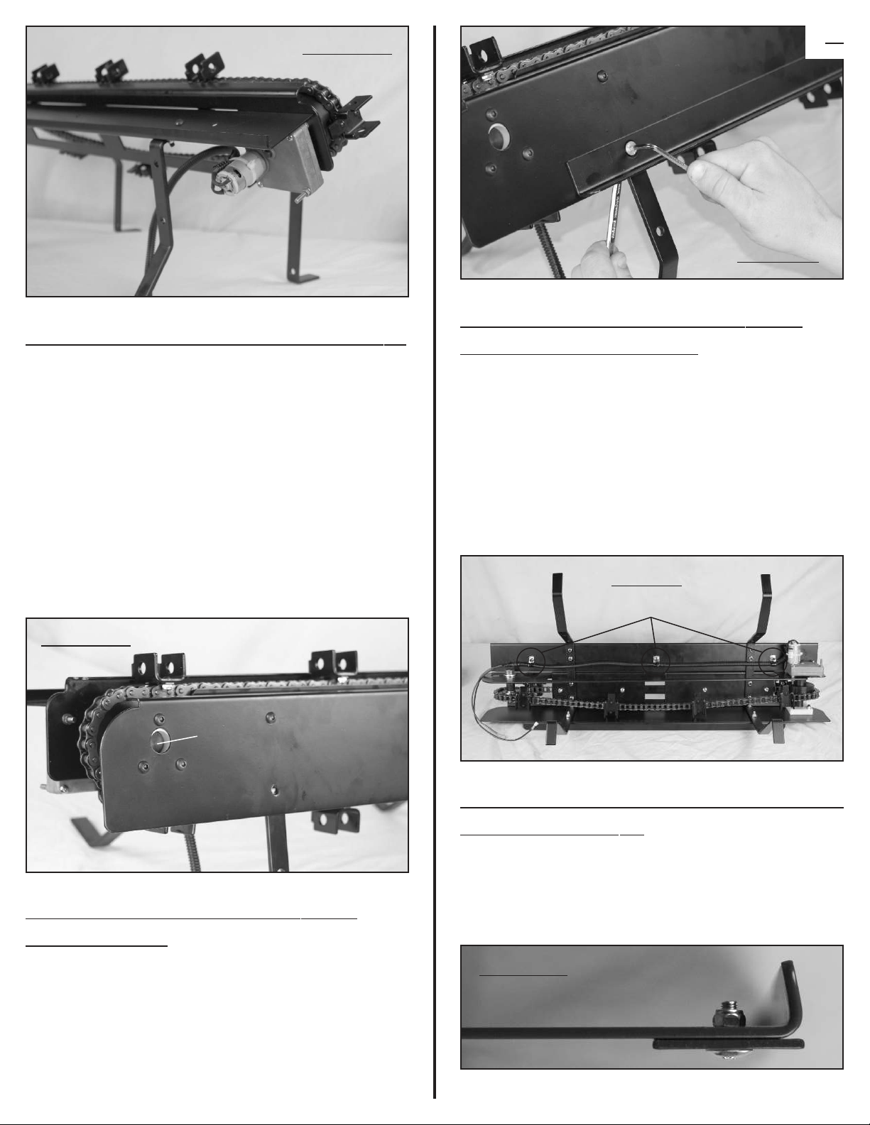
PHOTO P
PHOTO Q
STEP 11: Attach the Self-Adhesive
Target Spots to the Targets
STEP 12: Battery Charging and
SystemTest
Important: Do not overcharge the battery.
Nevercharge the battery while connected to the
Shootin’ Gallery. Charge ina well-ventilated area.
Use the provided Charger (1001480) to charge the
Battery (1000545). Connect the alligator clips to the
Battery before plugging the Charger into the wall. Make
sure the clips are connected tightly and securely to the
terminals on the Battery. The light on the Battery
charger will illuminate RED while charging and GREEN
when fully charged. Important: Do not overcharge
the Battery. To avoid damaging the Battery, remove
the Battery immediately when the light turns GREEN.
The ChargerDOES NOT turn itself off.
Avoid fully discharging the Battery. Deep discharging
can damage the Battery. When you notice the Shootin’
Gallery slowing down because the Battery charge is
low, stop and recharge the Battery. It may take several
hours to charge the Battery. Monitor indicator light.
WARNING: Keep hands and clothing clear
of chain,sprocket, and othermoving parts.
Make sure the switch is turned OFF. Carefully
connect the Red Wire to the Red battery ter-
minal and the black wire to the black battery terminal.
Place the Battery in the Battery Box and replace the
access panel and secure with the wing bolt. Make sure
wires are not pinched when replacing the access panel.
WARNING: Keep hands and clothing clear
of chain,sprocket, and othermoving parts.
Turn power switch ON. Targets should move from left
to right as you face the front of the Shootin’ Gallery.
(If not, check Battery connections.)
Carefully use a small stick such as a ruler or yardstick
to knock over a couple of the targets. As the fallen targets
rotate around the chain, they should reset automatically.
Turn switch off.
CONGRATULATIONS: Youare now ready to
set up your Shootin’ Gallery foruse. Read
instructions carefully.
SETTING UP AND USING YOUR
SHOOTIN’ GALLERY
1. Place the Shootin’ Gallery on level, soft ground
where there is a good backstop, such as a hill or berm
of soft earth. A .22 caliber bullet can travel as much as
a mile before losing energy. Be sure that if you miss
the target, your round will be stopped safely. Do not
place the shootin’ gallery on an elevated surface. The
Shootin’ Gallery must be at the same level as the
shooter’s feet. Always shoot from a position directly in
front of the Shootin’ Gallery. Shooting from an angle
could cause ricochet or prevent targets from falling.
2. Inspect the Shootin’ Gallery for damage and loose
or missing parts before each use. Tighten any loose
bolts or screws (impact from shooting can loosen
them). DO NOT USE IF PRODUCT IS DAMAGED,
MISSING PARTS, OR IF TARGETS ARE DEFORMED.
Replacement parts are available from Battenfeld
Technologies, Inc. www.battenfeldtechnologies.com
3. Inspect wires for wear and make sure they are
properly secured.
4. WARNING: Keep hands and clothing clearof
chain,sprocket, and othermoving parts. Make
sure power switch is OFF and connect the fully
charged battery. Note: You may need to charge
battery before use. Turn power switch ON. Targets
should move from left to right as you face the front

of the Shootin’ Gallery. (If not, check the battery
connections.)
5. Return to the firing line, and when it is safe to do
so, fire at the targets. As a round strikes the target, it
will tip back out of sight. As the targets return to their
starting position, they will automatically reset. Only
one shooterat a time.
WARNING: If the Shootin’ Gallery stops
unexpectedly orotherwise malfunctions,
follow these steps:
1. Cease fire.
2.
Make sure all weapons are unloaded with actions open.
3.
When it is safe to do so, approach the Shootin’ Gallery
4. Turn power switch OFF and disconnect the battery.
5. If you cannot identify and fix the problem, contact
Battenfeld Technologies, Inc. www.battenfeldtechnologies.com
Note: Your Shootin’ Gallery is provided with 2 spare
fuses. Additional fuses are readily available at most
automotive stores or automotive departments.
WARNING: Use only AGC 3-Amp Fuses.
WARNING: Always turn powerOFF and
disconnect the battery before servicing or
storing the Shootin’ Gallery
MAINTANING AND STORING YOUR
SHOOTIN’ GALLERY
WARNING: Turn powerswitch OFF and dis-
connect battery before servicing drive system.
Lubricate the chain with light-weight gear oil such as
bicycle chain oil at least twice a year, or more often if
the chain appears dry.
Chain tension is set at the factory, but you should
check it after final assembly and before each use.
Important: If the chain is too tight, it can cause prema-
ture wear and/or damage the motor.
Caring forthe Drive System
1. Make sure that four targets are at the bottom of the
chain drive.
2.
Measure the distance from Tab “A” on the target bracket
to the edge of the drive system frame “B”. This measurement
should be between 1/2” and 5/8”. Adjust as needed.
To Check the ChainTension:(Photo R)
1. Loosen the
1/2
”-13 nut on the idler shaft.
2.
Disassemble the back cover and target reaction angle.
3.
Loosen the jam nut and tighten or loosen the 1/4”-20
tension screw until chain tension is correct.
4. Retighten the
1/2
”-13 Nut (watch for movement as
you tighten).
5. Retighten the Jam nut.
6. Check Chain tension again and repeat the process if
further adjustment is needed.
7. Re-assemble the back cover and steel angle.
To Adjust ChainTension:(Photo S)
Turn the power switch OFF and disconnect battery.
Store in a secure, dry location, away from children.
Storing the Shootin’ Gallery
The Shootin’ Gallery is not warrantied against
misuse, abuse, orcommercial use. Should you need
a replacement part, please contact Battenfeld Technologies, Inc.,
5885 W. Van Horn Tavern Rd., Columbia, MO 65203,
573-445-9200, www.caldwellshooting.com.
Ordering Replacement Parts
PHOTO R
PHOTO S
Tab A
Frame B
1/2”- 5/8”
Te nsionScrew
JamNut
1/2” - 13 Nut
Table of contents
Other Caldwell Accessories manuals