SAT102 heat nterface un t
4
Installat on
The SATK ser es HIUs are des gned for nstallat on n a sheltered
domest c env ronment (or s m lar), therefore cannot be nstalled
or used outdoors, .e. n areas d rectly exposed to atmospher c
agents. Outdoor nstallat on may cause malfunct on ng and
hazards.
If the dev ce s enclosed ns de or between cab nets, suffic ent
space must be prov ded for rout ne ma ntenance procedures. It s
recommended that electr cal dev ces are NOT placed underneath
the HIU, as they may be damaged n the event of leakage from
any hydraul c component of connect on.
If th s adv ce s not heeded, the manufacturer cannot be held
respons ble for any result ng damage.
In the event of a malfunct on, fault or ncorrect operat on, the
dev ce should be deact vated; contact a qual fied techn c an for
ass stance.
NOTE for all models:
If a non-return valve s fitted nto the domest c hot water (DHW)
cold water nlet, prov s on MUST be made to accommodate the
expans on of the DHW conta ned w th n the HIU.
Preparat on
After establ sh ng the pos t on where the HIU w ll be nstalled,
perform the follow ng operat ons:
•Mark the holes requ red for secur ng the HIU to the wall.
•Mark the pos t on of the water p pe connect ons.
Check the measurements aga n before nstall ng p pework and
electr cal cables.
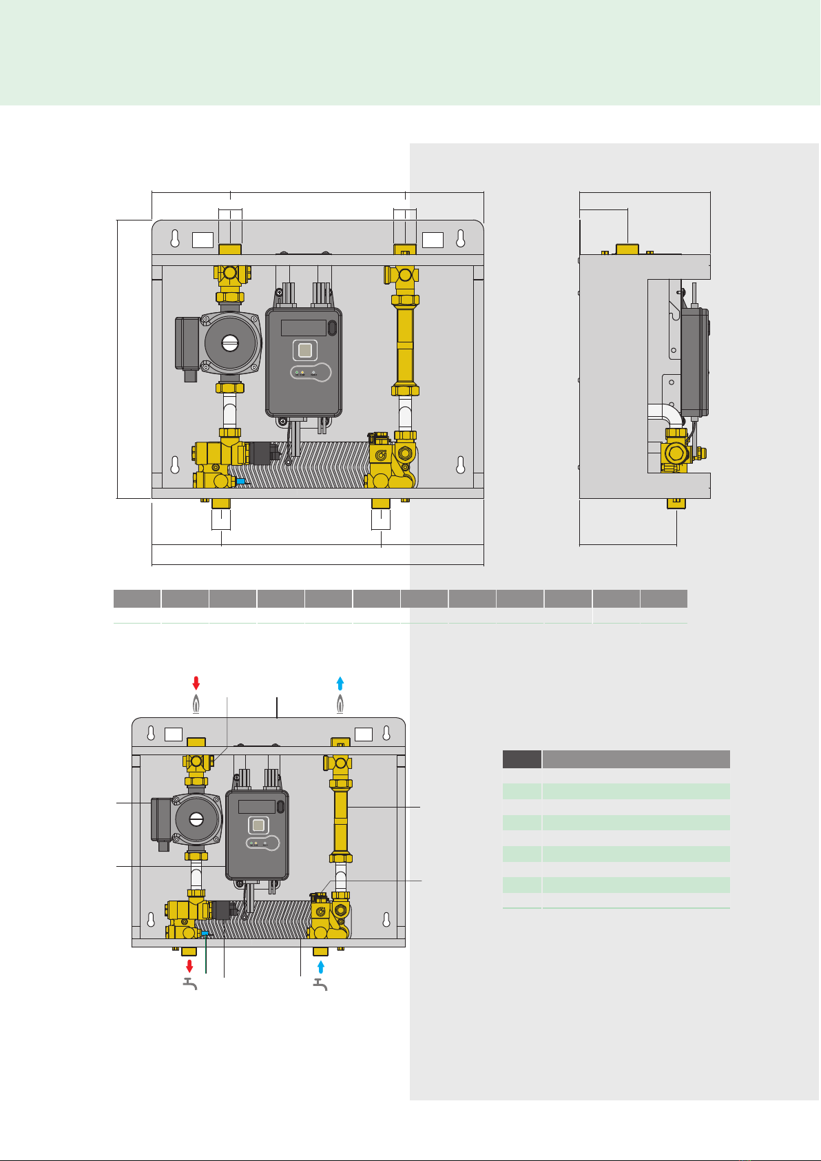
Hydraul c connect ons:
1connect on to the p pework from the central sed bo ler plant
2domest c water c rcu t connect on
Electr cal:
1electr c supply l ne 230 V (ac) – 50 Hz
2t me clock/thermostat l ne (potent al-free)
3central sed bus l ne for heat meter data transm ss on ( f
requ red)
4central sed electr c supply l ne for heat meter ( f requ red)
The whole system should be thoroughly flushed to remove any
debr s that may be n the supply p pework to the HIU and to the
domest c hot water p pework n the apartment before connect ng
the HIU.
F x the HIU to the wall
N.B.: the wall anchors (not suppl ed) can only guarantee effect ve
support f nserted correctly ( n accordance w th good techn cal
pract ce) nto walls bu lt us ng sol d or sem -sol d br cks. If
work ng w th walls bu lt us ng perforated br cks or blocks, mob le
d v d ng panels or any masonry walls other than those nd cated,
a prel m nary stat c test must be carr ed out on the support
system.
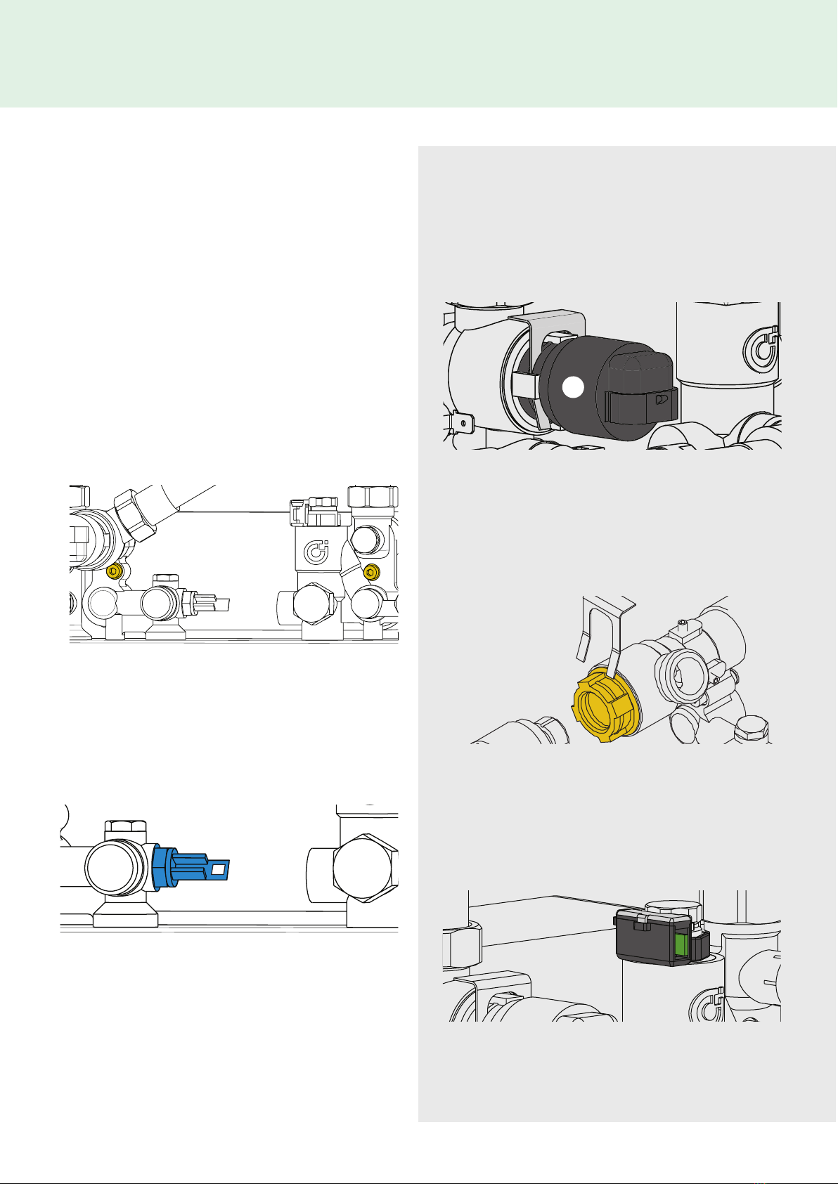
Isolat on Valves
Depend ng on the spec ficat on ordered, the HIU may be
suppl ed w th a var ety of solat on valves. We recommend that
all connect ons are fitted w th solat on valves to allow any
ma ntenance work to be carr ed out.
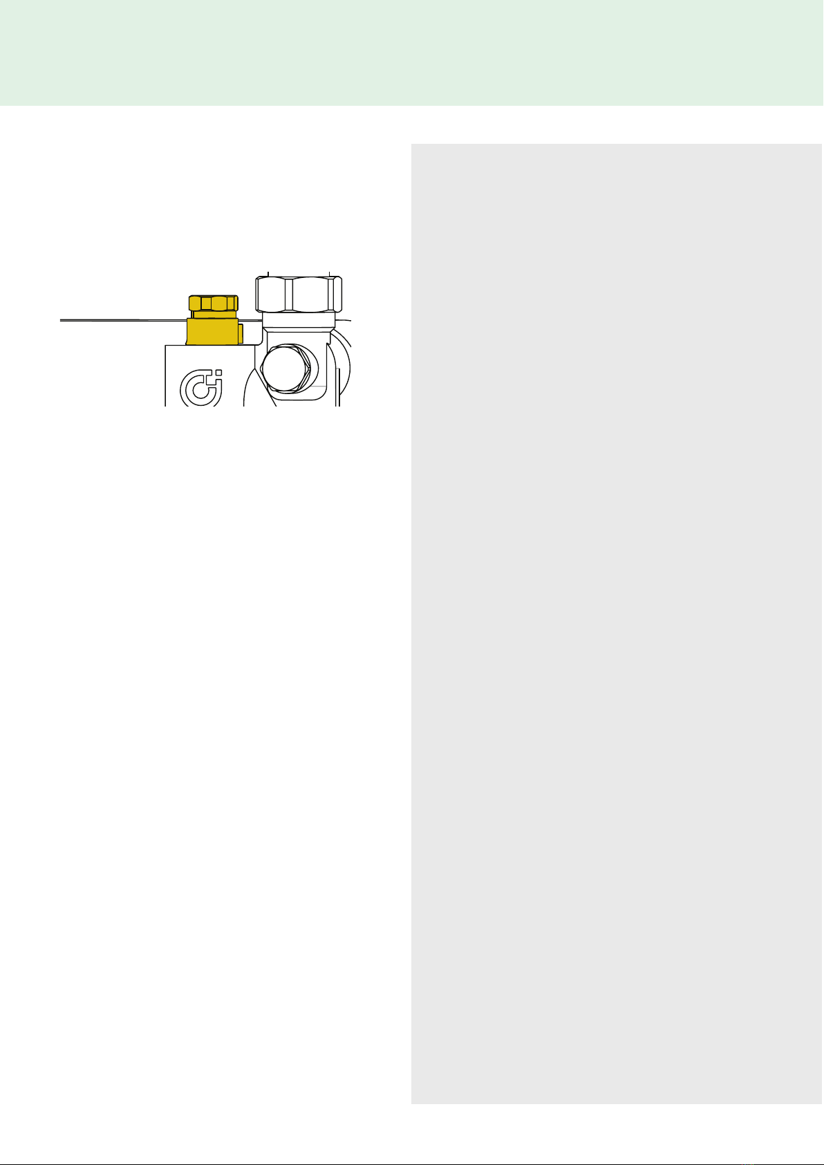
We would also recommend that the pr mary system ncludes a
flush ng bypass, w th an solat on valve, mmed ately upstream
of the HIU, to allow the pr mary system to be flushed pr or to
the first operat on of the un t.
Electr cal Connect ons
Make sure that the electr cal system can w thstand the
max mum power consumpt on of the appl ance, w th part cular
emphas s on the cross-sect on of the cables.
If n doubt, contact a qual fied techn c an to thoroughly check
the electr cal system.
Electr cal safety of the appl ance s only ach eved when t s
correctly connected to an effect ve earth ng system,
constructed as spec fied n current safety regulat ons. Th s s a
compulsory safety requ rement.
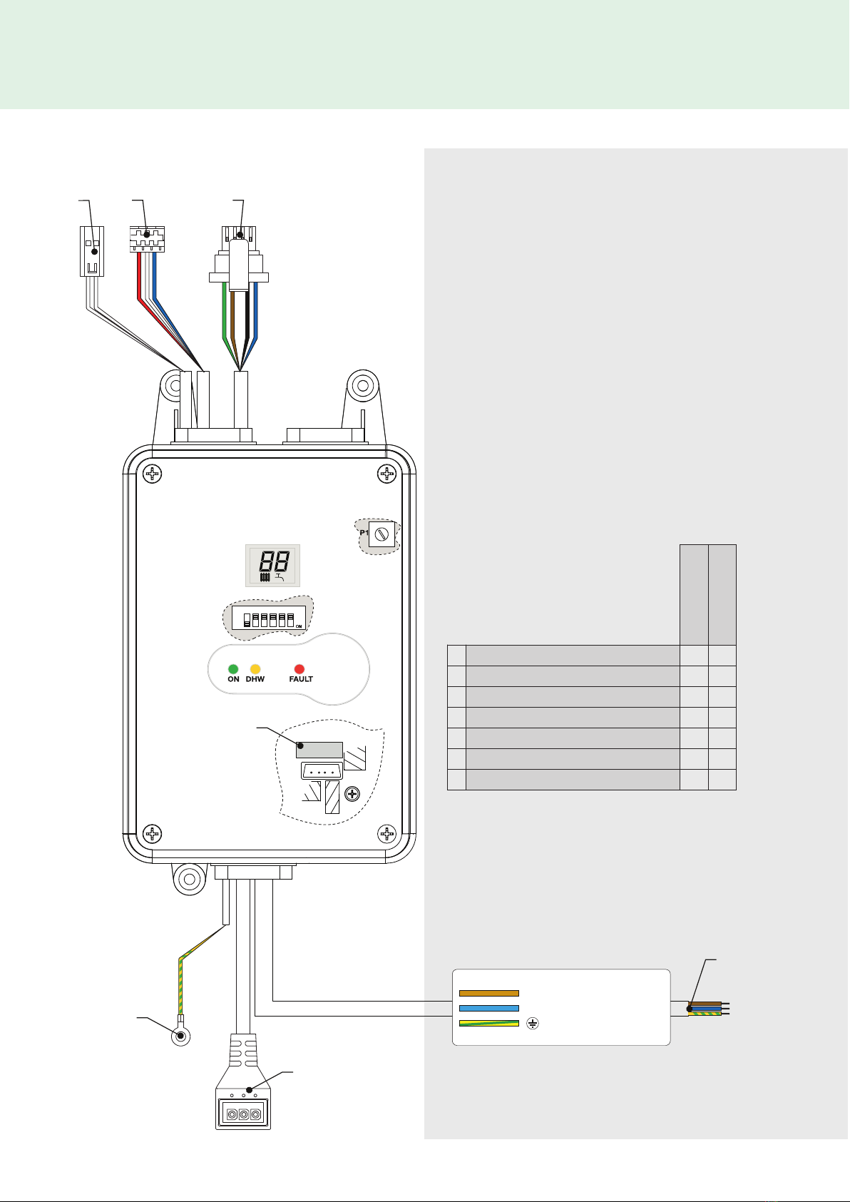
Connect on to the ma n supply
The dev ce s suppl ed w th an electr c supply cable - plug not
suppl ed.
The dev ce should be electr cally connected to a 230 V (ac)
s ngle phase + earth ma ns supply us ng the three-w re cable
marked w th the label as spec fied below, observ ng the LIVE (L)
- NEUTRAL (N) polar t es and the earth connect on.
Th s l ne must be connected to a c rcu t breaker dev ce.
F ll ng the pr mary heat ng system
Open the solat on valves on the connect ons to the central sed
bo ler plant to fill and pressur se the system to the des gn
pressure.
Once completed, vent the system and check the system
pressure aga n, repeat the fill ng process f necessary.
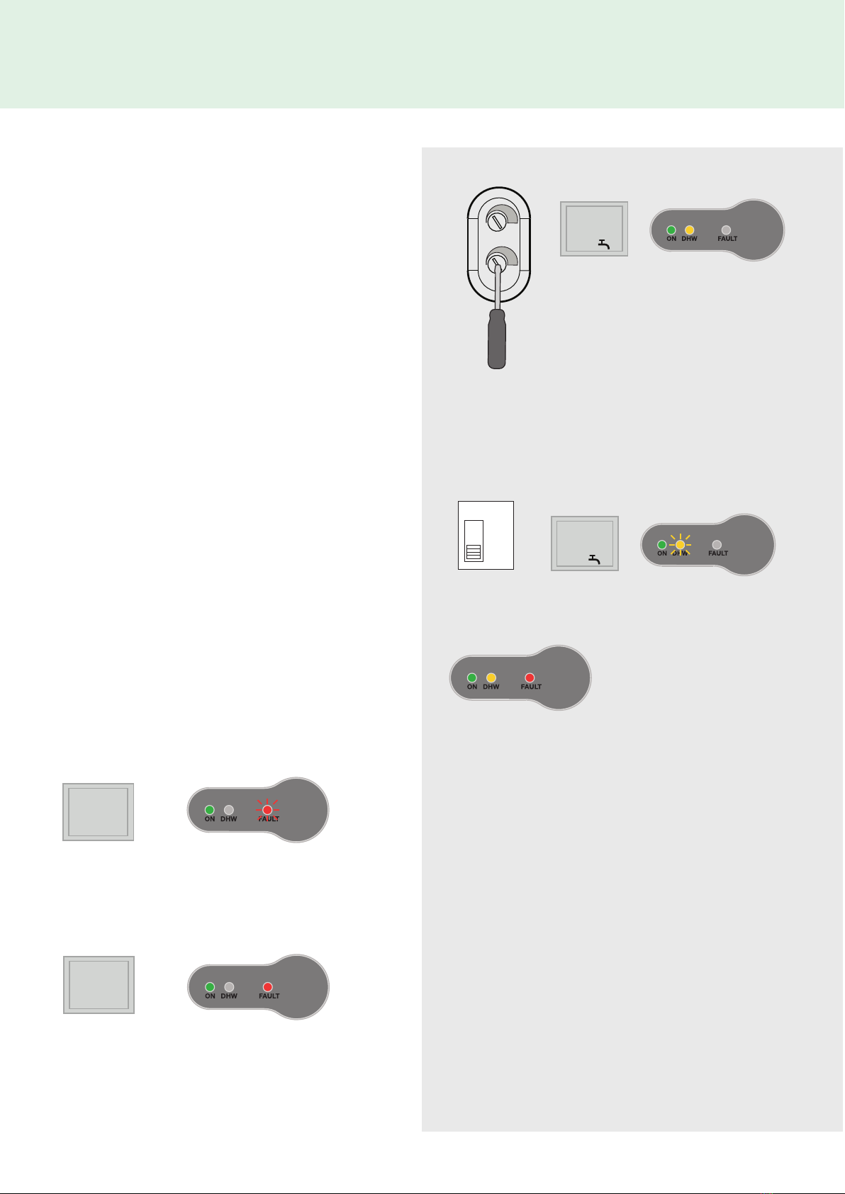
System start-up
Before us ng the HIU, v sually check that the hydraul c
connect ons are water t ght and the electr cal w r ng.
After complet ng the checks, sw tch on the electr c ty supply to
the HIU and check for the presence of any error s gnals.
If error s gnals are nd cated, el m nate the fault us ng the
procedure descr bed on page 6.
For HIUs w th an ntegral pump the follow ng appl es;
Once the HIU s hydraul cally filled (pr mary and
secondary), the HIU should be left permanently connected
to the ma ns supply and sw tched on. Th s allows the un t
to operate ts pump ant -clog protocol.