SATK20 & SATK30
4
Technical Specification - SATK20
Medium: Water
Max. percentage of glycol 30%
Max. temperature: 85˚C
Max. working pressure: Primary circuit: 10 bar
Domestic hot water: 10 bar
Nom. DHW heat exchanger net output: 50 kW
Max. recommended primary circuit flow rate: 1.2 m³/h
DHW circuit max. flow rate: 18 l/m (0.3 l/s)
Min.flow rate to activate domestic flow sensor: 2.7 l/m ±0.3
Max. differential pressure on domestic
water modulating valve: ∆p 0.9 bar
Max. differential pressure on mixing valve: ∆p 0.9 bar
Power supply: 230 V (ac)±10% 50 Hz
Power consumption: 105 W (SATK 20203)
Protection class: IP 40
Pump: UPS 15/60
Pump bypass setting: 0.45 bar
Actuator: stepper 24 V
Probes: NTC 10 kΩ
Safety thermostat: 55˚C ±3
Technical Specification - SATK30
Medium: Water
Max. percentage of glycol 30%
Max. temperature: 85˚C
Max. working pressure: Primary circuit: 16 bar
Secondary circuit: 3 bar
Domestic hot water: 10 bar
Nom. heating exchanger net output: 15 kW
Nom. DHW heat exchanger net output:
SATK30103: 50 kW
SATK30105: 75 kW
Max. recommended primary circuit flow rate: 1.2 m³/h
DHW circuit max. flow rate: 18 l/m (0.3 l/s)
Min.flow rate to activate domestic flow sensor: 2.7 l/m ±0.3
Max. differential pressure on domestic
water modulating valve: ∆p 0.9 bar
Power supply: 230 V (ac)±10% 50 Hz
Power consumption: 105 W
Protection class: IP 40
Pump: UPS 15/60
Pump bypass setting: 0.45 bar
Actuator: stepper 24 V
Probes: NTC 10 kΩ
Safety relief valve setting: 3 bar
Safety thermostat: 55˚C ±3
Expansion vessel: 7.5 litre
Pressure switch: opening 0.4 bar - closing 0.8 bar
Material
Components: brass BS EN 12165 CW617N
Pipes: stainless steel
Frame: RAL 9010 sprayed steel
Protective shell cover: PPE
Exchanger: brazed stainless steel
Installation
The SATK series HIUs are designed for installation in a sheltered
domestic environment (or similar), therefore cannot be
installed or used outdoors, i.e. in areas directly exposed to
atmospheric agents. Outdoor installation may cause
malfunctioning and hazards.
If the device is enclosed inside or between cabinets, sufficient
space must be provided for routine maintenance procedures. It
is recommended that electrical devices are NOT placed
underneath the HIU, as they may be damaged in the event of
discharge from the safety valve, if it is not connected to a
discharge tundish (SATK30103 and SATK30105), or in the event
of leaks occurring at the hydraulic fittings.
If this advice is not heeded, the manufacturer cannot be held
responsible for any resulting damage.
In the event of a malfunction, fault or incorrect operation, the
device should be deactivated; contact a qualified technician for
assistance.
NOTE for all models:
If a non-return valve is fitted into the domestic hot water
(DHW) cold water inlet, provision MUST be made to
accommodate the expansion of the DHW contained within the
HIU.
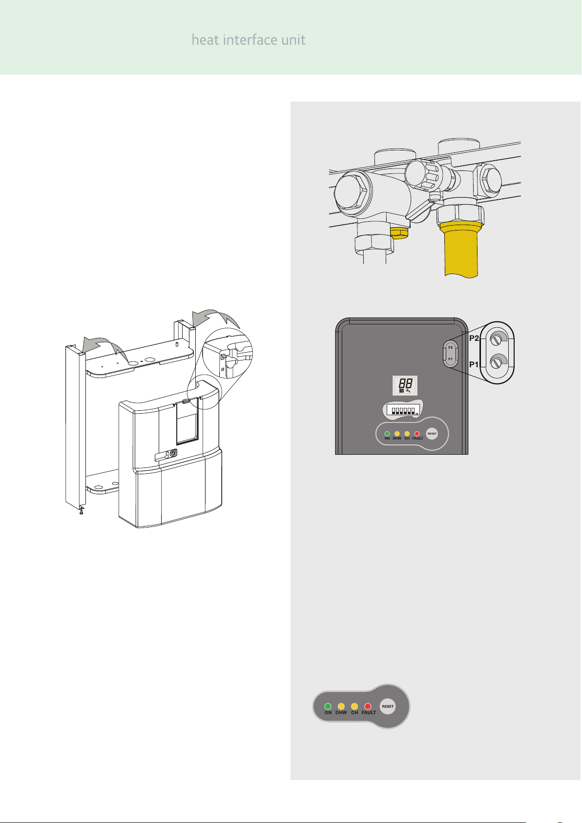
Preparation
After establishing the position where the HIU will be installed,
perform the following operations:
•Mark the holes required for securing the HIU to the wall.
•Mark the position of the water pipe connections.
Check the measurements again before installing pipework and
electrical cables.
Hydraulic connections:
1connection to the pipework from the centralised boiler
plant
2heating circuit connection
3domestic water circuit connection
4discharge from safety relief valve
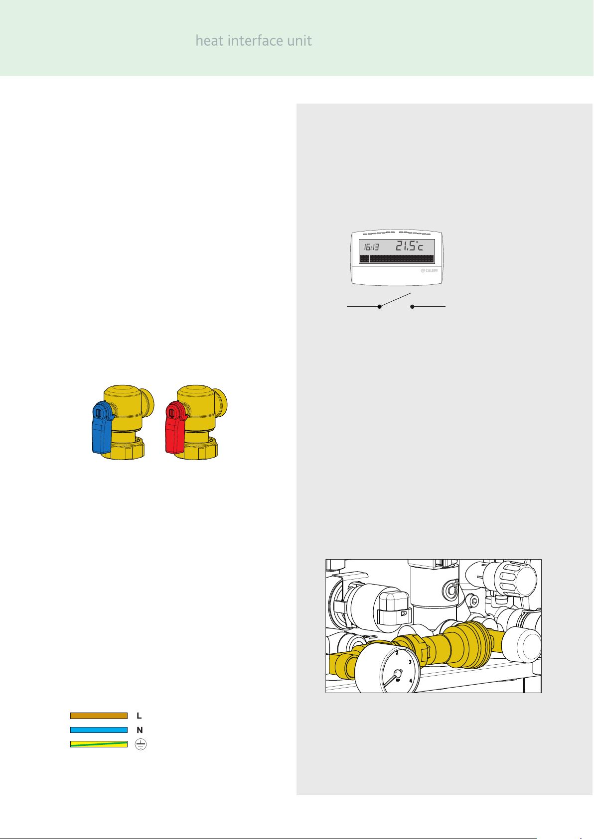
Electrical:
1electric supply line 230 V (ac) – 50 Hz
2time clock/thermostat line (potential-free)
3centralised bus line for heat meter data transmission (if
required)
4centralised electric supply line for heat meter (if required)