Commissioning
Filling the centr l he ting system
Open the shut-off valves (not supplied) on the connections to the
centralised line and, in the central heating system, proceed with
filling the system to the design pressure. Once these procedures
are complete, vent the system and check its pressure again (repeat
the filling process if necessary).
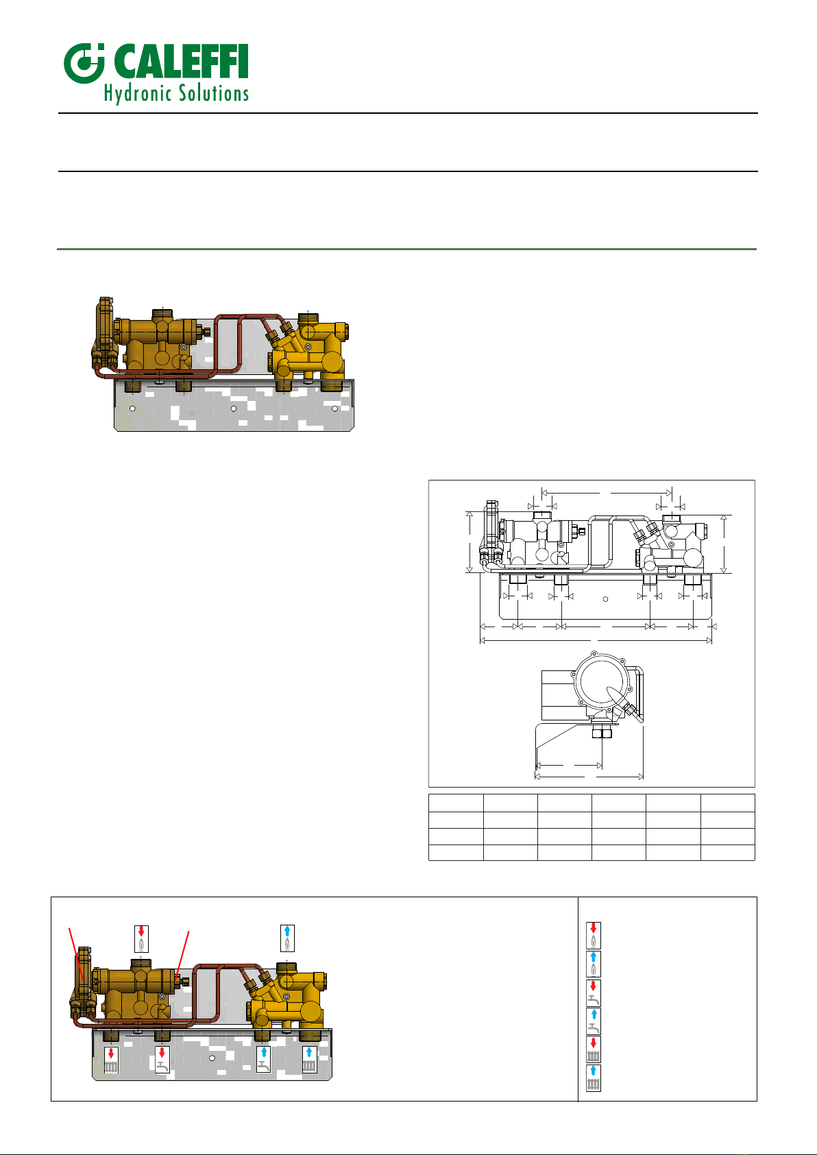
Exch nger prehe ting function
In order to keep pipe sections between the risers and the
apartment heating system from cooling and consequently to speed
up the response to demands for DHW production, SATK12313 HIU
is equipped with a manual by-pass that makes it possible to
maintain a minimum flow of water circulating through the heat
exchanger primary circuit.
To activate the preheating function turn knob (A).
M inten nce
All maintenance procedures should be carried out by an authorised
technician.
Regular maintenance guarantees better efficiency and helps to
save energy.
Before carrying out any maintenance, repairs or replacement of
parts, proceed as follows:
- Close the shut-off valves
- Empty the HIU.
He t exch nger repl cement
- Remove the heat exchanger by loosening the 2 hex socket fixing
screws (B)
- Replace the heat exchanger and the O-rings.
- Tighten the two fixing screws to a maximum torque of 3 N·m (B).
2
Inst ll tion
The SATK series HIU is designed for installation in a sheltered
domestic environment (or similar), therefore it cannot be installed or
used outdoors, i.e. in areas directly exposed to the elements.
Outdoor installation may cause malfunctioning and hazards.
If the device is enclosed inside or between cabinets, sufficient space
must be provided for routine maintenance procedures. It is advisable
to avoid positioning electrical devices under the HIU as they may be
damaged in the event of leaks from hydraulic fittings. If this advice is
not heeded, the manufacturer cannot be held responsible for any
resulting damage. In the event of a malfunction, fault or incorrect
operation, the device should be deactivated; contact a qualified
technician for assistance.
Prep r tion
After having established the point of installation of the device,
perform the following operations:
• ark the holes required to secure the HIU to the wall
• ark the position of the hydraulic connections
Check the measurements again and begin laying the following lines:
1. connection to the centralised line
2. heating circuit connection
3. domestic water circuit connection.
Before installation, it is recommended to carry out accurate flushing
of all the pipes of the system in order to remove any residue or
impurities that could endanger correct operation of the HIU. Fix the
HIU to the wall.
N.B.: the wall anchors can only guarantee effective support if
inserted correctly (in accordance with good technical practice) into
walls made of solid or semi-solid bricks. If working with walls built
using perforated bricks or blocks, mobile dividing panels or any
masonry walls other than those indicated, a preliminary static test
must be carried out on the support system.
Hydr ulic connections
Hydraulic connections to the centralised line must be made using
manual shut-off valves which allow any necessary maintenance work
to be carried out without having to empty the centralised system.
It is advisable to install manual shut-off valves also on the lower
terminals for connection to the apartment heating system.
ake sure all connections are perfectly watertight.
WARNINGS
These instructions must be read and understood before installing and maintaining the device.
CAUTION! FAILURE TO FOLLOW THESE INSTRUCTIONS COULD RESULT IN A SAFETY HAZARD!
CAUTION!
THE PRODUCT SUPPLIED WITH THIS INSTRUCTION SHEET WILL BE DESIGNATED “DEVICE” HEREINAFTER
1 The device must be installed, commissioned and maintained by qualified technical personnel in accordance with national regulations and/or applicable local bylaws.
2 If the device is not installed, commissioned and maintained correctly in accordance with the instructions provided in this manual, it may not work properly and may
endanger the user.
3 Clean the pipes of any particles, rust, incrustations, limescale, welding slag and any other contaminants. The hydraulic circuit must be clean.
4 ake sure all connection fittings are watertight.
5 When connecting water pipes make sure the threaded connections are not mechanically overstressed. Over time this may result in breakage, causing water damage
and/or personal injury.
6 Water temperatures higher than 50°C can cause severe burns. When installing, commissioning and servicing the device, take the necessary precautions so that
these temperatures do not constitute a threat for personal safety.
7 In the case of particularly hard or impure water, there must be suitable provision for filtering and treating the water before it enters the device, in accordance with
statutory legislation. Otherwise the device may be damaged and will not work properly.
8 Any use of the device other than its intended one is prohibited.
9 Any combination of the device with other system components must be made taking the operational characteristics of both units into consideration. An incorrect
combination could impair operation of the device and/or system.
LEAVE THIS ANUAL AS A REFERENCE GUIDE FOR THE USER. DISPOSE OF THE PRODUCT IN CO PLIANCE WITH CURRENT LEGISLATION
THE ANUFACTURER RESERVES THE RIGHT TO CEASE PRODUCTION AT ANY TI E AND TO AKE ANY CHANGES DEE ED USEFUL OR NECESSARY
WITHOUT THE OBLIGATION OF PRIOR NOTICE.
SAFETY INSTRUCTIONS
A
B