CALEFFI Altecnic SATK22 Series Guide

Caleffi group
SATK22
heat nterface un t
Installat on Operat on & Ma ntenance Instruct ons

SATK22
1
These instructi ns must be read and underst d
bef re installing and maintaining the HIU.
CAUTION! FAILURE TO FOLLOW THESE
INSTRUCTIONS COULD RESULT IN A SAFETY
HAZARD!
1The dev ce must be nstalled, comm ss oned and
ma nta ned by qual fied techn cal personnel n accordance
w th nat onal regulat ons and/or relevant local
requ rements.
2If the dev ce s not nstalled, comm ss oned and ma nta ned
correctly n accordance w th the nstruct ons prov ded n
th s manual, t may not work correctly and may endanger
the user.
3Flush the p pework thoroughly before nstall ng the HIU to
remove any part cles, rust, ncrustat ons, l mescale, weld ng
slag and any other contam nants.
The water c rcu ts must be clean and free from debr s.
4Make sure that all connect on fitt ngs are watert ght.
5When connect ng water p pes, make sure that threaded
connect ons are not mechan cally overstressed. Over t me
th s may result n breakage, caus ng water damage and/or
personal njury.
6Water temperatures h gher than 50˚C may cause severe
burns. When nstall ng, comm ss on ng and ma nta n ng the
dev ce, take the necessary precaut ons so that these
temperatures w ll not be hazardous for people.
Content
Funct on 1
Safety nstruct ons 1
D mens ons and connect ons 3
Techn cal spec ficat on 3
Components & schemat c SATK2210 & SATK2220 4
Components & schemat c SATK2230 & SATK2240 5
Installat on 6
Heat meter nstallat on 8
Electr cal connect ons 8
Remote user nterface 11
Comm ss on ng 10
Remote user nterface - qu ck gu de 12
Heat ng funct ons 13
DHW funct ons 15
Pr mary flow rate l m tat ons 17
C rculator - curves and sett ngs 18
Aux l ary m crosw tch 19
Modbus 20
Safety and alarms 21
Electr c c rcu t board and connect ons 22
Ma ntenance 23
Fault find ng 26
Check L st 27
Safety Instruct ons
SATK22
Funct on
The SATK22 HIU allows ndependent control of heat regulat on
and domest c hot water product on w th n central sed heat ng
systems or systems served by d str ct heat ng networks.
The heat nterface un t features except onal flex b l ty of
nstallat on and remote controllable smart electron c funct ons
des gned to enhance effic ency of the system.
NOTE: Due to the spec ficat on ordered, or the country of
dest nat on, the actual un t may d ffer from those shown.
Product Range
SATK22103 D rect wall-mounted HIU for LOW temperature
heat ng. Domest c hot water capac ty 50 kW1
SATK22105 D rect wall-mounted HIU for LOW temperature
heat ng. Domest c hot water capac ty 60 kW1
SATK22203 D rect wall-mounted HIU for MEDIUM
temperature heat ng. Domest c hot water capac ty 50 kW1
SATK22205 D rect wall-mounted HIU for MEDIUM
temperature heat ng. Domest c hot water capac ty 60 kW1
SATK22305 D rect wall-mounted HIU for HIGH temperature
heat ng. Domest c hot water capac ty 60 kW1
SATK22403 D rect wall-mounted HIU for HIGH temperature
heat ng. Domest c hot water capac ty 50 kW1 w th pr mary
pump
SATK22405 D rect wall-mounted HIU for HIGH temperature
heat ng. Domest c hot water capac ty 60 kW1 w th pr mary
pump
1Pr mary s de head > 50 kPa, pr mary flow temperature 70˚C,
DHW 10 to 50˚C.
WARNING

SATK22
2
General Informat on
•Please leave the manual as a reference gu de for the user.
•D spose of any packag ng n an appropr ate manner, most
of wh ch can be recycled.
•In th s Installat on, Operat on and Ma ntenance gu de we
have endeavoured to make the nformat on as accurate as
poss ble.
We cannot accept any respons b l ty should t be found
that n any respect the nformat on s naccurate or
ncomplete or becomes so as a result of further
developments or changes to the products.
Key to SymbolsSafety Instruct ons
7In the case of part cularly hard or mpure water, there must
be su table prov s on for filter ng and treat ng the water
before t enters the dev ce, n accordance w th current
leg slat on. Fa lure to do so may result n the HIU becom ng
damaged or work ng ncorrectly.
8Any use of the HIU other than t’s ntended use s
proh b ted.
9Any coupl ng of the dev ce w th other system components
must be made wh le tak ng the operat onal character st cs
of both un ts nto cons derat on.
10 An ncorrect coupl ng could comprom se the operat on of
the dev ce and/or system.
NOTE: R sk of electr c shock. L ve parts. Shut off the electr c
supply before open ng the HIU cover.
1Dur ng nstallat on and ma ntenance operat ons, always
avo d d rect contact w th l ve or potent ally hazardous parts.
2The dev ce must not be exposed to dr pp ng water or
hum d ty, d rect sunl ght, the elements, heat sources or h gh
ntens ty electromagnet c fields.
Th s dev ce cannot be used n areas at r sk of explos on or
fire.
3The dev ce must be connected to an ndependent b polar
sw tch. If work has to be done on the dev ce, sw tch off the
electr c supply first. Do not use dev ces w th automat c or
t me reset, or wh ch may be reset acc dentally.
4Use su table automat c protect on dev ces n compl ance
w th current leg slat on.
5The dev ce must always be earthed before t s connected to
the electr c supply. If the dev ce has to be removed, always
d sconnect the earth connect on after d sconnect ng the
electr c supply. Check that the earth connect on has been
made to the h ghest of standards under current leg slat on.
6Electr cal nstallat on must only be carr ed out by a qual fied
techn c an, n accordance w th current requ rements.
7The HIU does not conta n asbestos or mercury.
8The HIU should only be used by an author sed adult.
NOTES:
1Install water hammer arresters to compensate for any
overpressure n the domest c water c rcu t.
2In the presence of hot water re-c rculat on or f a check valve
s fitted nto the domest c cold water nlet, su table dev ces
must be used to accommodate the expans on of the
med um conta ned w th n the system and the heat nterface
un t.
3All hydraul c connect ons must be v sually checked wh le
pressur s ng the system. V brat on dur ng transport may
cause the connect ons to become loose. If a fitt ng needs to
be t ghtened apply an appropr ate t ghten ng torque,
otherw se the components may become damaged.
Mater al
Components: brass BS EN 12165 CW617N
P pes: sta nless steel
Frame: RAL 9010 sprayed steel
Exchanger: brazed sta nless steel
Insulat on
Protect ve shell cover: EPP
Dens ty: 45 kg/m3
Work ng temperature range: 3 to 90˚C
Thermal conduct v ty: 0.04 W/mK
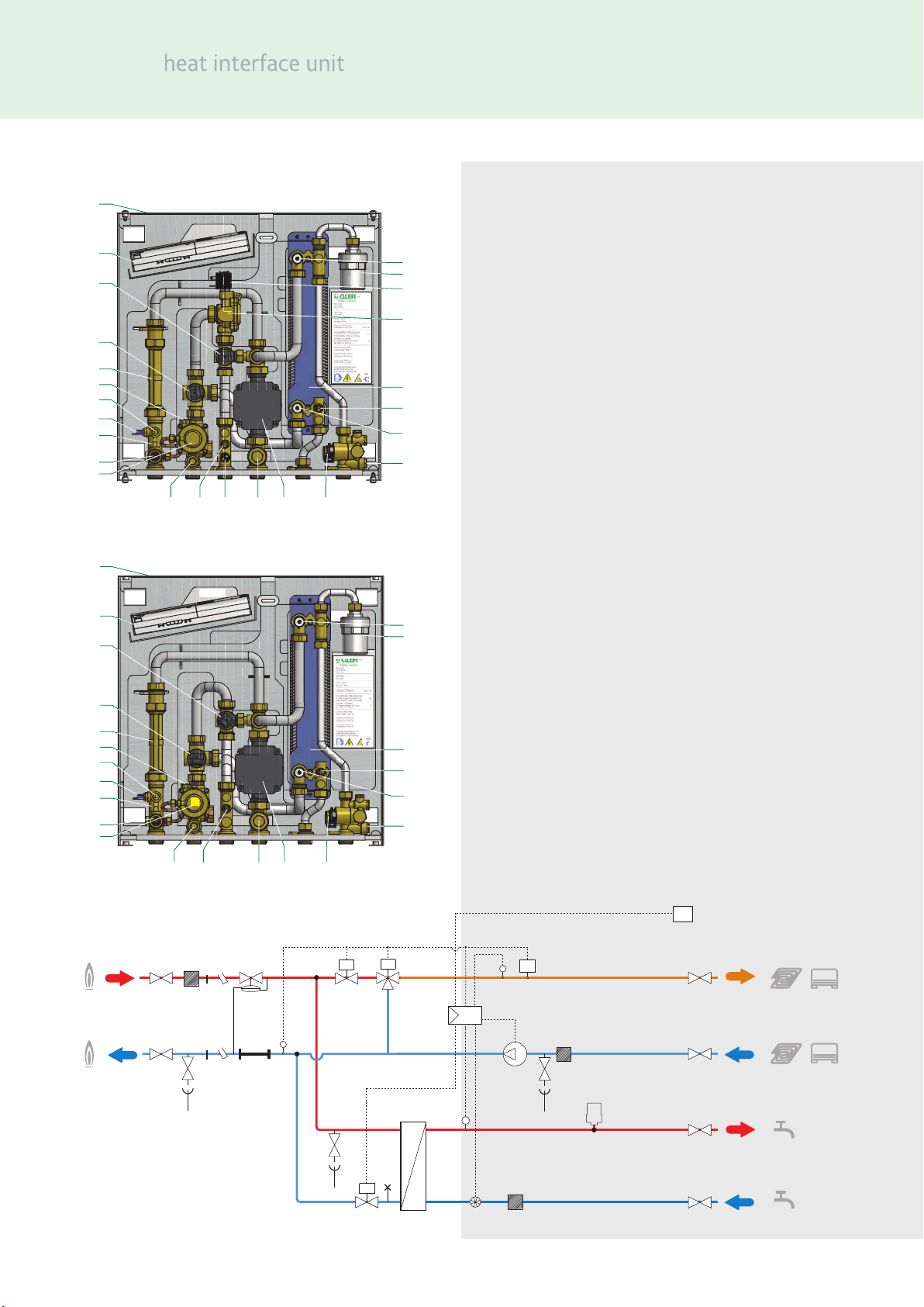
Hightemperaturecircuit flow
Hightemperaturecircuitreturn
Mediumtemperaturecircuit flow
Mediumtemperaturecircuitreturn
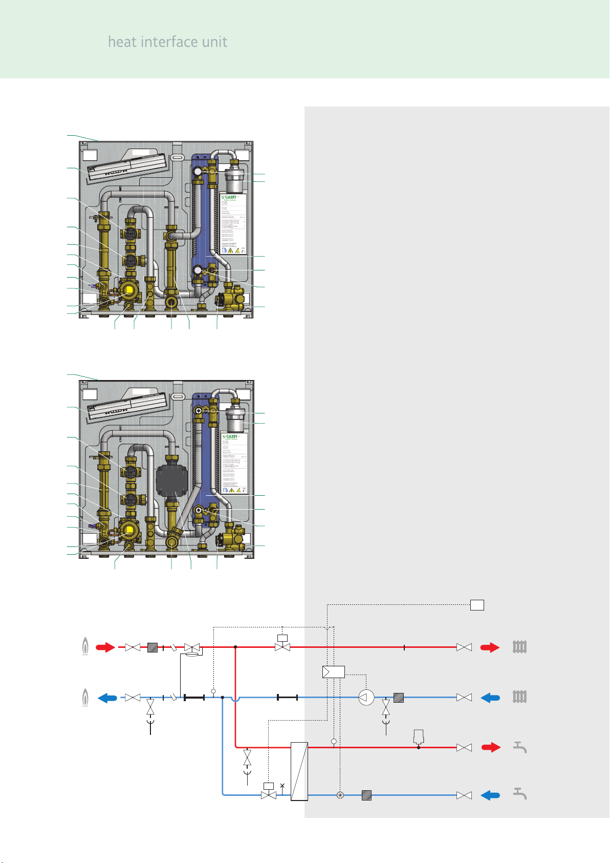
Lowtemperaturecircuit flow
Lowtemperaturecircuitreturn
Domestic hotwateroutlet
Domestic cold water inlet
Primary circuit flow
Primary circuit return

SATK22
3
D mens ons
Connect ons
Techn cal Spec f cat on
Med um: Water
Max. percentage of glycol 30%
Max. temperature: 90˚C
Max. stat c work ng pressure: Pr mary: 10 bar
Secondary: 10 bar
Domest c hot water: 10 bar
Pr mary c rcu t Nom nal flow rate: 1.2 m3/h
Nom nal pressure loss on pr mary c rcu t: 0.5 bar
Max. d fferent al pressure: 6 bar
Domest c water c rcu t max. flow rate: 24 l/m n (0.4 l/s)
M n.flow rate to act vate domest c flow sensor: 2.0 l/m n ±0.3
Power supply: 230 V (ac)±10% 50 Hz
Max. power consumpt on: 80 W
SATK2230 20W
Protect on class: IP 40
Pump: UPM3 15-70
Actuator: stepper 24 V
Probes: NTC 10 kΩ
Safety rel ef valve sett ng: 3 bar
Safety thermostat - STK2210: 55˚C ±3
857070 60 60
490
75 130
245
42 28
444
514
All connections G¾B

SATK22
4
*only ncluded n SATK2210
Components - SATK2210 (LOW temperature)
Components - SATK2220 (MEDIUM temperature)
Components - SATK2210 & SATK2220
Item Component
1 Frame
2 Electron c regulator
3 2-way modulat ng valve - heat ng
4 2-way modulat ng valve - DHW
5 130 mm space for heat meter
6 ¼”F pressure port
7 Return temperature probe
8 Connect on for M10 x 1 heat meter return probe
9 Pr mary dra n cock
10 D fferent al pressure control valve
11 Mesh stra ner + ¼” F pressure port
12 Heat ng flow temperature probe
13*Safety thermostat
14 Secondary dra n cock + mesh stra ner
15 Pump
16 Flow meter (turb ne + sensor)
17 Mesh stra ner
18 Heat ng exchanger pr mary dra n
19 DHW temperature probe
20 DHW heat exchanger
21 Connect on for M10 x 1 heat meter flow probe
22*Thermal safety soleno d valve (normally closed)
23*Thermal safety valve actuator
24 Water hammer arrester
25 Heat exchanger pr mary c rcu t a r vent
Schemat c D agram SATK2210 and SATK2220
1
2
3
4
5
6
7
8
9
10
11 12 14 15 16
21
25
24
20
19
18
17
TS
TA
2
V
V
V
V
V
V
3
4
7
12
13*
5
6
8
9
10
11
21
14
15
19
24
20
17
16 17
22*
23*
25
* SATK2210. only (LOW temperature)
1
2
3
4
5
6
7
8
9
10
11 12 13 14 15 16
21
25
24
23
22
20
19
18
17

SATK22
5
Components - SATK2230 (HIGH temperature)
Components - SATK2240 (HIGH temperature w th pump)
Schemat c D agram SATK2230 and SATK2240
Components - SATK2230 & SATK2240
Item Component
1 Frame
2 Electron c regulator
3 2-way modulat ng valve - heat ng
4 2-way modulat ng valve - DHW
5 130 mm space for heat meter
6¼”F pressure port
7 Return temperature probe
8 Connect on for M10 x 1 heat meter return probe
9 Pr mary dra n cock
10 D fferent al pressure control valve
11 Mesh stra ner + ¼” F pressure port
12*¹/” connect on for DPCV code 789122
13 Secondary dra n cock + mesh stra ner
14#Pump
15*Spool p ece
16 Flow meter (turb ne + sensor)
17 Mesh stra ner
18 Heat ng exchanger pr mary dra n
19 DHW temperature probe
20 DHW heat exchanger
21 Connect on for M10 x 1 heat meter flow probe
22 Water hammer arrester
23 Heat exchanger pr mary c rcu t a r vent
*only ncluded n SATK2230
#only ncluded n SATK2240
1
2
3
4
5
6
7
8
9
10
11 13 14 16
21
23
22
20
19
18
17
1
2
3
4
5
6
7
8
9
10
11 12 13 15 16
21
23
22
20
19
18
17
TA
2
V
V
V
V
V
V
3
4
7
5
6
8
9
10
11
21
13
14#
19
22
20
23
16 17
18
12*
15*
* SATK2230. only
# SATK2240. only

SATK22
6
Installat on w th Mount ng Bracket
Ensure the wall s structurally su table for mount ng the HIU, follow the nstruct on below.
•Us ng the mount ng bracket as a template mark the pos t on of the holes requ red to secure the HIU to the wall. Ensure the
mount ng bracket s hor zontal.
•Hang the HIU onto the wall bracket and secure to the wall us ng the fix ng holes prov ded.
•Mark the pos t on of the hydraul c connect ons
Check the measurements aga n and based on the above connect on d agram and the d mens ons shown on page 3, proceed w th the
nstallat on of the follow ng l nes:
1connect on to the central system l ne
2heat ng c rcu t connect on
3domest c water c rcu t connect on
NOTE:
We recommend nstall ng manual shut-off valves, espec ally on the connect ons to the pr mary l nes, thus allow ng any necessary
ma ntenance work to be carr ed out w thout hav ng to empty the central sed system.
Before nstallat on, t s recommended to carry out thorough flush ng of all the p pes of the system n order to remove any res due or
debr s that could endanger correct operat on of the HIU.
In order to fac l tate these operat ons a manual bypass flush ng valve s ava lable (code 789110).
Installat on
The SATK22 HIU s des gned for nstallat on n a sheltered domest c env ronment (or s m lar), therefore t cannot be nstalled or
used outdoors, .e. n areas d rectly exposed to the weather. Outdoor nstallat on may cause malfunct on ng and hazards.
If the appl ance s enclosed ns de or between cab nets, suffic ent space must be prov ded for rout ne ma ntenance procedures.
It s NOT recommended to place electr cal dev ces underneath the HIU, as they may become damaged n the event of leaks
occurr ng at the hydraul c fitt ngs. If th s adv ce s not heeded, the manufacturer cannot be held respons ble for any result ng
damage.
In the event of a malfunct on, fault or ncorrect operat on, the appl ance should be de-act vated; contact a qual fied techn c an for
ass stance.
Before nstallat on, t s recommended to carry out a thorough flush ng of all the p pe work n order to remove any debr s or
mpur t es that could prevent the correct operat on of the HIU.
In order to fac l tate these operat ons a manual bypass flush ng valve s ava lable (Code 789110).
NOTE:
When the first fix bracket s not used we recommend nstall ng manual shut-off valves, espec ally on the connect ons to the pr mary
l ne, thus allow ng any necessary ma ntenance work to be carr ed out w thout hav ng to empty the central sed system.
Hydraul c connect ons - revers b l ty
Installat on of the SATK22 heat nterface un t s revers ble (top down) w th the except on of the LOW temperature Un t SATK2210.
Installat on n the two pos t ons s poss ble w th or w thout the first fix bracket Code 789023.

SATK22
7
Installat on w th mount ng bracket
Installat on w th mount ng bracket and first fix bracket
Ensure the wall s structurally su table for mount ng the HIU, follow th s nstruct on below.
•Us ng the mount ng bracket as a template mark the pos t on of the holes requ red to secure the HIU to the wall. Ensure the
mount ng bracket s hor zontal.
In order to fac l tate these operat ons a manual bypass flush ng valve s ava lable (code 789110).
Connect ons at the bottom
Connect ons at the top
Connect ons at the bottom

SATK22
8
Hydraul c connect ons
Based on the d mens ons and connect on d agram on page 3.
•Connect on to the central pr mary heat ng system.
•Connect to the apartment heat ng system.
•Connect to the domest c hot water system (DHW).
Connect ons at the top
Heat meter nstallat on
The HIU s des gned to house a compact heat meter (w th
ncorporated return probe) w th 1” threaded connect ons and
length of 130 mm.
Before carry ng out any ma ntenance, repa r or part
replacement work, proceed as follows:
•Sw tch off the electr c supply
•Remove the cover
•Close the shut-off valves
•Dra n the HIU us ng the dra n cocks prov ded
•Remove the spool p ece (A)
•Remove the cap (B)
•Install the flow meter on the return p pe. To t ghten the nuts
apply max mum t ghten ng torque of 25 Nm, tak ng account
of the recommendat ons of the heat meter manufacturer.
•Install the flow probe n the M10 pocket (B).
Please refer to the heat meter techn cal data sheets for further
nformat on.
Electr cal Installat on
Connect ng to the electr c ty supply
The HIU s suppl ed w th an electr c supply cable wh ch s not
fitted w th a plug.
The appl ance should be electr cally connected to a 230 V (ac)
s ngle-phase + earth ma ns supply us ng the three-w re cable
marked w th the label as spec fied below, observ ng the LIVE (L)
- NEUTRAL (N) polar t es and the earth connect on. Th s l ne
must be connected to an On/OFF sw tch.
A
B
Electric supply
NOTE:
When nstall ng w th the connect ons at
the bottom secure w th safety screws as
shown.
Install the SATK22 as shown and us ng
seal ng washers connect the HIU to the
valves on the first fix bracket.

SATK22
9
Electr cal Installat on Cont nued
Connect ng to the electr c ty supply
To extend the cable f necessary, use a flex ble cable su table for
k tchen and heat ng appl ances and for home, k tchen and
office nstallat ons, also n hum d env ronments subject to
med um levels of mechan cal stress (e.g. H05V2V2-F: Uo/U
300/500 V). Cable m n mum cross-sect on 3 x 0.
75 mm2.
Make sure that the electr cal system can w thstand the
max mum power consumpt on of the HIU, w th part cular
emphas s on the cross-sect on of the w res.
If you have any doubts, contact a qual fied techn c an to
request a thorough check of the electr cal system.
Electr cal safety of the appl ance s only ach eved when t s
correctly connected to an effect ve earth ng system,
constructed as spec fied n current safety regulat ons. Th s s a
compulsory safety requ rement. Observe the appl cable
regulat ons n force n the country of nstallat on.
Use the cable pathway prov ded, as shown n figure 1.
Opt onal electr cal connect ons
The electron c c rcu t board has a door on the front prov d ng
access to term nal boards for opt onal w r ng (see chapter
“Electron c C rcu t Board” on page 22).
The connect ons n quest on are all low voltage or
potent al-free.
Any w r ng must be d rected toward the exter or of the HIU,
us ng the pathways prov ded n the nsulat on and on the frame
(the one that s not used for rout ng the electr c supply cable,
see figure 2).
All these l nes can be routed through a s ngle ded cated
raceway, separate from the 230 V electr c cable one and
anyway separate from any other l ve cables.
Remote user nterface connect on
The HIU user nterface has the dual funct on of control dev ce
and room thermostat.
The remote user nterface can be nstalled on cover of the HIU
or n the room n a pos t on where the temperature
measurements w ll be of s gn ficance for control of the heat ng
funct on ( n a heated room n a pos t on where the temperature
read by the thermostat s not affected by any nearby heat
sources).
Installat on on the cover of the HIU
If the remote user nterface s fitted n the ded cated locat on
on the cover of the HIU, the thermostat funct on must be
d sabled ( n th s case an external thermostat must be used, as
descr bed n the next sect on).
The adjacent figures show how to nstall the remote control
un t:
•Feed the cable from the regulator through the hole n the
cover (3).
•Feed the cable from the regulator through the rear of the
nterface (4).
•Connect the two w res to the term nals on the electron c
c rcu t board (the cable s not polar sed) (5).
1
2
3
4
5
6
7
•Close the remote user nterface and pos t on t n ts
hous ng on the cover (6), (7); f necessary, secure the
user nterface from ns de the cover by means of self
tapp ng screws and washers.
•Plug n the connector (8).
The thermostat funct on s enabled by default (refer to the
remote control user manual for d sabl ng t).

SATK22
10
A
B
C
Installat on n the room
Use the cable outlet prov ded for connect ng the remote user
nterface to the electron c c rcu t board.
The chrono-thermostat funct on has to be enabled through the
remote control.
Refer to the ded cated user manual for the procedure.
Use of an external room thermostat
An external room thermostat, f nstalled, must be w th
potent al-free contact.
The external thermostat has to be connected to the term nals
“RT” shown n the adjacent figure.
The term nals can be accessed by remov ng the door on the
HIU electron c regulator (see page 22).
In case the thermostat funct on of the remote user nterface s
enabled, any external thermostat w ll work n parallel
(management of d fferent temperature zones).
Alternat vely, when the thermostat funct on of the remote user
nterface s d sabled, the nterface can be used to define the
hourly programm ng of the space heat ng funct on for all
thermostats connected to the term nal “RT”.
Refer to the user nterface ded cated manual.
Comm ss on ng
F ll ng the central heat ng system
Open the shut-off valves on the connect ons to the pr mary
heat ng system and the central heat ng system, proceed w th
charg ng the system to the des gn pressure.
Once these procedures are complete, vent the system and
check the pressure aga n (repeat the fill ng process f necessary)
N.B. dur ng the procedures for vent ng/dra n ng the system use
su table measures to avo d the r sk of any l qu d dr pp ng onto
the electron c components.
Once these procedures are complete, vent the system and
check ts pressure aga n (repeat the fill ng process f necessary)
N.B. dur ng the procedures for vent ng/dra n ng the system use
su table measures to avo d the r sk of any l qu d dr pp ng onto
the electron c components.
System start-up
Before start ng the HIU, v sually check the hydraul c
connect ons for any s gns of leakage and all the electr c
connect ons.
After fin sh ng the check, sw tch-on the electr c supply to the
HIU and check for the presence of any error s gnal.
If there are any, el m nate the fault nd cated (see page 26) and
proceed w th sett ng the set po nt of the domest c water and
heat ng cycles, programm ng the remote user nterface
accord ng to the des red temperatures and t mes, and check ng
the operat ng cycles.
Comm ss on ng Cont nued
F tt ng the cover
F t the cover on the HIU by nsert ng the p ns (A) n the
locat ons prov ded (B).
Secure the cover by t ghten ng the 4 screws prov ded (C).
EXP PORT OTS RT PREPAID AUX RS-485 BUS

SATK22
11
The d g ts n the centre of the d splay show the current amb ent temperature, f the thermostat funct on s enabled.
In case the latter s d sabled, the d g ts show DHW temperature and heat ng flow temperature when the HIU s n operat on, “--.-”
when n stand-by.
Remote User Interface Qu ck Gu de
Select ng the act ve serv ces
(DHW/heat ng) Press the <mode> key
repeatedly to scroll through the
var ous ava lable operat ng modes.
Select ng set po nts, current t me and
comfort funct on
Press the <set> key repeatedly to set the
current t me, set po nt temperatures and
comfort funct on. The value can be mod fied
by turn ng knob <R>.
OFF
DHW only (“summer mode”) Heating + DHW (“winter mode”)
(mode)
DHW ON/OFF
Heating ON/OFF
(set)
Current time/date
Set point temperature
k outside temperature compensation
(day/night)
Daytime/night-time setting
(temp)
Temperature
display
(ambient set point
+ probes)
(prog)
Heating hourly
programming and
“comfort” function
(reset)
Resettable error reset
(R)
+/-
Current hours, minutes and day Daytime ambient temperature (*)
Night-time ambient temperature (*) Heating flow temperature
(SATK2210 & SATK2220)
DHW temperature

SATK22
12
Remote User Interface Qu ck Gu de
Primary limit/set return
temperature in DHW mode (**)
Comfort function (ON/OFF or
according to weekly program)
Primary limit/set return temperature
in Heating mode (**)
(*) f the thermostat funct on of the remote user nterface s enabled.
(**) f these set po nts cannot be changed you must set parameter t07 to value 0 n the techn cal menu (see “access to techn cal
menu” below). Parameter t07= 1 “freezes” the operat ng set po nts to prevent nadvertent mod ficat ons by the user.
Current ambient temperature set
point (*)
DHW probe temperature
Heating flow probe temperature # Primary return probe temperature
# SATK2210 & SATK2220
Heat interface unit in OFF mode
Access to the technical parameters Technical parameter t00
To ex t the menu, wa t a few seconds or press the <reset> key. Re-enable the requ red serv ces us ng the <mode> key.
Refer to the remote control user manual for the hourly programm ng of space heat ng and DHW comfort funct on.
Temperature d splay
Press the <temp> key repeatedly to d splay
the current amb ent temperature set po nt
and the temperature values read by the
three probes of the HIU.
(*) f the thermostat funct on of the remote user nterface s enabled.
Access to techn cal menu
Press the <mode> key repeatedly to set the
HIU to OFF status.
Hold the <set>, <day/n ght> and <temp>
keys pressed together for 10 seconds.
Once “TSP” appears on the d splay, confirm
access by press ng the central knob <R>.
By rotat ng knob <R> t s poss ble to scroll
through the var ous parameters, wh ch can
then be ed ted, press ng and rotat ng knob
<R>.

SATK22
13
Heat ng Funct on
Heat ng flow temperature sett ng (SATK2210. and SATK2220.)
To set the flow temperature press the <SET> key unt l the
symbol n the red c rcle appears. Use the <R> knob to change
the value.
The flow temperature range s:
25–45˚C for SATK2210. (LOW temperature)
45–75˚C for SATK2203. (MEDIUM temperature)
Default Sett ng: set po nt regulat on
(techn cal parameter t01 = 0)
When heat ng cycle act vat on s requested by the room
thermostat, the c rculat on pump s powered wh le the m x ng
valve s opened gradually unt l the set po nt temperature s
reached. I
In the h gh temperature models (SATK2230 - SATK2240) the
valve s opened up to the max mum allowed (see Pr mary Flow
Rate L m tat on on page 17)."
The c rculat on pump s stopped and the modulat ng valve s
closed at the end of the heat ng cycle. The heat ng cycle ON
cond t on s nd cated by the bl nk ng symbol.
OPTIONAL SETTING: pr mary return temperature l m t
(techn cal parameter t01 = 1)
When heat ng cycle act vat on s requested by the room
thermostat, the c rculat on pump s powered wh le the m x ng
valve s opened gradually unt l the set po nt temperature s
reached ( n SATK2230 and SATK2240 the valve s open fully, up
to the max mum allowed), f the return temperature s lower
than or equal to the set l m t value.
In case th s cond t on s not met, n HIUs w th control of the
flow temp.(SATK2210 and SATK2220) the flow temperature s
reduced (by a max mum of 15˚C n SATK2220, and max mum
3˚C n SATK2210, n order to br ng return temperature w th n
the l m t values.
In SATK2230 and SATK2204 a reduct on of the heat ng flow
rate s operated. When the flow temperature/flow rate must be
reduced n order to l m t return, the con appears on the
d splay.
To set the flow temperature press the <SET> button unt l the
symbol n the green c rcle appears. Use the <R> knob to change
the value (*). The pr mary return l m t temperature range s:
15–42˚C for SATK2210 - LOW temperature
30–70˚C for SATK2220 - MEDIUM temperature
Heat ng flow/ pr mary return l m t temperature sett ng
To set the flow temperature press the <SET> key unt l the
symbol n the red c rcle appears; for the return temperature
l m t press the key unt l the symbols n the green c rcle are
d splayed. Use the <R> knob to change the value (*).
The flow temperature range s:
25–45˚C for SATK2210 - LOW temperature
45–75˚C for SATK2220 - n MEDIUM temperature
.

SATK22
14
Heat ng Funct on
OPTIONAL SETTING: modulat ng temperature regulat on w th
compensated set po nt (techn cal parameter t01= 2)
(SATK2210 & SATK2220)
When the funct on s enabled, the flow temperature s mod fied
(±10°C w th respect to the set po nt for HIU n HIGH
temperature, ±3°C f n LOW temperature) accord ng to the
temperature detected by the return probe n order to ma nta n
th s latter temperature value constant.
Th s keeps the actual thermal output of the slab under control,
and consequently also the amb ent thermal load. The thermal
response t me of the system s thus m n m sed.
Th s feature should not be used n comb nat on w th
thermostat c rad ator valves.
When the funct on s enabled the d splay shows the symbol
OPTIONAL SETTING: weather compensat on (techn cal
parameter t01 = 3)
When the funct on s enabled, the flow temperature s
calculated based on the temperature detected by the outs de
probe (opt onal), n accordance w th the curve shown below.
The “k” coeffic ent can be changed by press ng <SET> button
unt l the related sett ng appears.
The d splay shows the symbol .
(*) f these set po nts cannot be changed you must set
parameter t07 to value 0 n the techn cal menu (see “access
to techn cal menu” below). Parameter t07 = 1 “freezes” the
operat ng set po nts to prevent nadvertent mod ficat ons by
the user.
Atmospheric Temperature T (˚C)
MIN -5 0 5-15
MAX
10-10 302515 20
-20
k = 3.0
k = 2.5
k = 2.0
k = 1.5
k = 1.0
k = 0.5
k = 0.0
MAX is the set temperature value
MIN is 45°C for HIGH temp. HIUs, 25°C for LOW temp. ones.
Flow Temperature T (˚C)

SATK22
15
DHW Funct on
The DHW cycle always takes pr or ty over the heat ng cycle.
DEFAULT SETTING: fixed DHW set po nt (parameter t06=0)
When DHW cycle act vat on s requested, due to DHW tapp ng
by the user (detected by the domest c water flow meter), the
regulator modulates the valve open ng n order to adjust the
temperature detected by the domest c water probe to the
selected set po nt value. When tapp ng ends, the modulat ng
valve s fully closed.
The DHW cycle ON cond t on s nd cated by the bl nk ng
symbol.
OPTIONAL SETTING: pr mary return temperature l m t
(techn cal parameter t06 = 1)
When DHW cycle act vat on s requested, due to DHW tapp ng
by the user (detected by the domest c water flow meter), the
regulator modulates the valve open ng n order to adjust the
temperature detected by the domest c water probe to the
DHW set po nt value f the return temperature s less than or
equal to the set l m t. If th s cond t on s not met, the flow
temperature s reduced (by a max mum of 7°C down to a
temperature that can be no less than 40°C), n order to br ng
return temperature w th n the l m t values.
Due to the act vat on of the return temperature l m tat on
funct on, the DHW temperature can be lower than the set
value.
DHW/pr mary return l m t temperature sett ng
To set the DHW temperature press the <SET> key unt l the
symbol n the red c rcle appears; for the return temperature
l m t press the key unt l the symbols n the green c rcle are
d splayed. Use the <R> knob to change the value (*).
The range of poss ble DHW temperatures s 42–60°C, wh le the
range of poss ble return temperatures s 15–45°C.
(*) f these set po nts cannot be changed you must set parameter t07 to value 0 n the techn cal menu (see “access to techn cal
menu” below). Parameter t07 = 1 “freezes” the operat ng set po nts to prevent nadvertent mod ficat ons by the user.

SATK22
16
IMPORTANT!
•Any DHW product on that occurs dur ng the t me band
(3:00 -3:30) w ll be at 60°C.
•The cycle execut on t me band (3:00 - 3:30) s establ shed
n accordance w th the t me set on the remote control un t.
Incorrect t me sett ng w ll result n execut on of the
ant -leg onella funct on n a d fferent actual t me band.
Due to the effect of exchanger thermal nert a, temporary
DHW product on at h gh temperature could proceed also
beyond the t me of 3:30.
If the funct on s enabled thermostat c m x ng valves should
be nstalled on the users level (washbas n/shower, etc.).
DHW Comfort Funct on - Pre-heat, DHW Re-c rculat on
The comfort funct on can be, alternat vely, preheat ng of the
DHW plate heat exchanger or management of DHW
rec rculat on. They are enabled by sett ng to ON or PROG the
comfort funct on (see page 12).
DEFAULT SETTING: DHW exchanger preheat ng funct on
(parameter t02 = 0) Dur ng per ods when the domest c water
cycle s not used, f the DHW probe detects a temperature 10˚C
below the SET value, the regulator part ally opens the domest c
hot water modulat ng valve for the t me requ red (max. 5 m n.)
to br ng the exchanger to the cond t on where n t can assure
rap d DHW product on.
The act ve pre-heat ng cycle s nd cated by the bl nk ng
symbol. Th s funct on s of lower pr or ty than any domest c
water or heat ng cycles.
OPTIONAL SETTING: management of DHW rec rculat on n the
apartment (parameter t02 = 1)
In alternat ve to the DHW comfort funct on t s poss ble to
manage DHW rec rculat on, us ng a s m lar log c. Dur ng
per ods when the domest c water cycle s not used, f the DHW
probe detects a temperature 10˚C below the SET value, by
means of an aux l ary m crosw tch (see page 17), the regulator
closes the c rcu t supply ng the c rculat on pump (not suppl ed)
generat ng a DHW cycle last ng for a pre-set amount of t me.
Th s amount of t me s pre-set to 2 m nutes. It can be changed
by act ng on parameter t09 on the techn cal menu (1 un t = 10
seconds).
The c rculator has to be fed through the aux l ary m crosw tch
so that the control of rec rculat on s carr ed out by the heat
nterface un t. DHW rec rculat on (t02=1) d sables the other
funct ons operat ng on the aux l ary m crosw tch descr bed on
page 17. Refer to page 17 for the electr cal character st cs of the
m crosw tch.
Both comfort funct ons can be enabled accord ng to user
defined weekly t me programm ng. Refer to the remote user
nterface manual
Ant -Leg onella Funct on
DEFAULT SETTING: ant -leg onella funct on OFF (techn cal
parameter t08 = 0)
Enabl ng the ant -leg onella funct on by means of techn cal
parameter t08 = 1, n t me band 3:00 - 3:30:
•the DHW set po nt w ll be temporar ly ncreased to the
max mum value (60˚C) - the comfort/rec rculat on funct on
w ll be forced ON.
As a result of the temperature r se of the set po nt, at t me 3:00
a comfort funct on (e ther pre-heat ng or rec rculat on) w ll be
tr ggered, br ng ng the temperature to a value close to 60˚C,
such as to rap dly reduce the presence of any bacter a.
Dur ng execut on of the cycle, the user nterface d splay w ll
show the bl nk ng symbol (refer to the adjacent figure).

SATK22
17
Pr mary Flow Rate L m tat on
Pr mary flow rate l m tat on n heat ng mode.
DEFAULT SETTING: no l m tat on (techn cal parameter t03 =
100)
Dur ng start-up of the heat ng cycle from cold, e.g. on change
over from n ght-t me amb ent set po nt to the dayt me set
po nt, the HIU may demand a s gn ficantly h gher pr mary flow
rate than the des gn one, because of the low temperatures of
the secondary med um.
Th s effect s far greater w th h gh temperature systems n
wh ch, dur ng the trans ent to the des gn operat ng cond t on,
h gh thermal power values may be transferred from the pr mary
c rcu t to the secondary c rcu t. Th s effect can be restr cted by
lengthen ng the trans ent, sett ng a l m t on the max mum
pr mary flow rate that can be w thdrawn n heat ng mode.
The flow rate l m tat on s mposed by controll ng the
max mum open ng of the pr mary c rcu t modulat ng valve.
The relat onsh p between the degree of open ng (%) and Kv of
the c rcu t that connects the pr mary flow to the secondary
flow s shown n the graphs.
Pr mary flow rate l m tat on n DHW mode.
DEFAULT SETTING: no l m tat on (techn cal parameter t04 =
100)
L kew se, you can establ sh a l m t to the pr mary flow rate that
can be tapped for nstantaneous DHW product on.
The flow rate l m tat on s mposed by controll ng the
max mum open ng of the pr mary c rcu t modulat ng valve.
S nce latter s controlled by a d fferent al pressure l m ter, t s
poss ble to supply d rect correspondence between the open ng
pos t on of the valve and the c rculat ng flow rate (*).
N.B. Any l m tat on must be assessed n accordance w th the
effect ve thermal character st cs of the res dent al un t served.
(*) The correspondence between valve pos t on and flow rate s
nd cat ve. Graphs obta ned w th pressure head upstream of the
HIU = 50 kPa.
A maximum degree of opening (%) can be set via technical
menu parameter t03
Max opening (%)
Kv (m3/h)
706050 80 10090
0
0.25
0.50
0.75
1.00
1.25
1.50
1.75
2.00
A maximum degree of opening (%) can be set via technical
menu parameter t04.
Max opening (%)
Flow rate (l/h)
706050 80 10090
0
200
400
600
800
1000
1200

SATK22
18
C rculator - Curves and Sett ngs
The HIU s equ pped w th a Grundfos c rculator model UPM3
AUTO-L 15-70.
By default, the c rculator sett ng s w th the max mum
proport onal head character st c.
Press ng the front key br efly produces the sequence of LEDs
correspond ng to the selected hydraul c character st c. A couple
of seconds after press ng the key, the c rculator aga n produces
a sequence of LEDs show ng the nstantaneous power
consumpt on:
•1 yellow LED l t: power between 0 and 25% of Pmax;
•2 yellow LEDs l t: power between 25 and 50% of Pmax;
•3 yellow LEDs l t: power between 50 and 75% of Pmax;
•4 yellow LEDs l t: power between 75 and 100% of Pmax.
To change the character st c, hold down the front key for more
than two seconds and then press the same key repeatedly unt l
reach ng the requ red character st c (refer to the adjacent
figure).
Hav ng dent fied the requ red character st c (head - flow rate
chart shown below) wa t for about ten seconds for the sett ng
to be accepted by the c rculator, wh ch w ll then revert to the
sequence of LEDs show ng power consumpt on.
A long press of the front key (>10 seconds) locks the pump
sett ng, prevent ng poss ble ncorrect mod ficat ons of the
curve.
Unlock ng can be done n the same way, w th a long press
(>10 s) of the front key.
The pump also has a self-d agnost cs system to reveal any
poss ble operat ng problems.
Any problem detected s shown by a sequence of LEDs:
PERFORMANCE
2 s.
SELECTED SETTING
C
CURVE TYPE
PROPORTIONAL
PROPORTIONAL
PROPORTIONAL
CONSTAN T
FIXED SPEED
FIXED SPEED
FIXED SPEED
FIXED SPEED
CONSTAN T
CONSTAN T
LED SEQUENCE
CURVE TYPE LED SEQUENCE
ALARM STATUS
Blocked
Supply voltage low
Electrical error
H (m w.g.)
G (m3/h)
p (bar)
0.6
0.4
0.3
0.2
0.1
02.521.5
0.5
0.5
3.53
1
6
4
3
2
1
5
70.7
0.8 8
Constant head
Proportional head
Constant speed
Factory setting

SATK22
19
Aux l ary M crosw tch
The HIU s equ pped w th a contact, dr ven by a relay
ncorporated n the c rcu t board, the ntervent on log c of
wh ch can be programmed n accordance w th requ rements by
sett ng techn cal parameter t05.
Each event l nked to operat on of the HIU s l nked to a
numer cal value, accord ng to the follow ng table:
Clos ng of the contact on the occurrence of mult ple events
cond t ons s programmed by sett ng parameter t05 to a value
correspond ng to the sum of the s ngle events/cond t ons.
We g ve some pract cal examples below:
example 1 - Dr v ng an external pr mary flow pump, normally
OFF.
The contact must be closed f any HIU funct on s act ve (DHW
product on, heat ng, pre-heat ng)
Parameter t05 must be set to: 1 + 2 + 4 = 7
example 2 - D st nct on of consumpt on for DHW product on
from total consumpt on ( n comb nat on w th heat meter
equ pped w th ded cated funct on)
The contact must be closed both f DHW tapp ng s n progress
and f act vat on of the comfort funct on s requested
(pre-heat ng or rec rculat on).
Parameter t05 must be set to 1 + 4 = 5.
Clos ng of the m crosw tch s shown on the user nterface by
the symbols shown alongs de.
N.B. f the DHW rec rculat on funct on s enabled w th t02 = 1
(see page 16) the aux l ary m crosw tch ntervent on log c
descr bed above s not operat onal. In th s case, the contact s
used to control the rec rculat on pump.
Connect on
For nformat on on how to access the ded cated term nals,
consult the “Electron c C rcu t Board” sect on on page 22.
N.B.: the aux l ary m crosw tch can be used to dr ve electr c
loads d rectly, tak ng account of the follow ng operat ng l m ts:
Max. voltage: 230 V ac
Max.current: 3 A
If the electr c load to be controlled s not ncluded w th n the
parameters nd cated an external relay must be nterposed.
Events - C nditi ns Value
DHW tapp ng n progress 1
Heat ng cycle n progress 2
Comfort cycle (pre-heat ng/rec rculat on) n progress 4
HIU OFF 8
Error not act ve 16
Error act ve 32
Other manuals for Altecnic SATK22 Series
1
This manual suits for next models
7
Table of contents
Other CALEFFI Recording Equipment manuals