Caleido M1/M1CR User manual

Heating element M1 / M1CR - M2 / M2CR
RADIATOR TECHNICAL MANUAL
DEAR CUSTOMER
Thank you for choosing a Caleido product.
This manual contains all the necessary information concerning the correct installation, use and maintenance of the radiator.
Please read this manual carefully and keep it in a safe place. Remember that, in the event of transfer to another installation destination, it must
accompany the radiator.
IMPORTANT WARNINGS
The appliance may be used by children over the age of 8 and by persons with reduced physical, sensory or mental capabilities, or a lack of
experience or the necessary knowledge, as long as they are supervised or have received instructions on the safe use of the appliance and
understand the dangers involved. Cleaning and maintenance to be carried out by the user must not be carried out by children.
Children under the age of 3 must be kept at a distance and must not play with the radiator or its parts. Children between 3 and 8 years of age may
only turn the appliance on/off if they have received instructions regarding its safe use and understand the dangers. Children between the ages of 3
and 8 years should NOT plug in, adjust or clean the appliance, nor should they carry out maintenance on it.
CAUTION - DO NOT use in small rooms when these are occupied by people who cannot leave the room alone, unless they are under constant
supervision
CAUTION - The radiator may only be used to support towels or similar, and these must not exceed a total weight of 5 kg.
CAUTION - Only use the screws and plugs supplied or replace them with others which have the same or better mechanical properties. CAUTION -
This appliance is only intended for heating textiles washed in water.
CAUTION - If antifreeze liquid leaks from the electric radiator, avoid contact with skin and eyes; avoid inhaling and swallowing.
CAUTION - Do not use this device in the immediate vicinity of a bathtub, shower or swimming pool. CAUTION - The device is not suitable for drying
wet clothes, this would pose a serious safety risk to the user.
CAUTION
Some parts of this product can get VERY HOT and cause burns. Particular care must be taken where
children and/or vulnerable persons are present.
CAUTION
To avoid overheating, do not cover the device. CAUTION
Do not climb on the product.
ELECTRICAL CONNECTION
All the characteristics relating to the electrical part of the radiator, which has previously undergone various tests, are found on the label on
the underside of the appliance, next to the power cable. We recommend that you read the above label.
CAUTION
The appliance must be disconnected from the electricity supply during installation, maintenance and cleaning.
Check the correct supply voltage, observing the values on the label on the radiator next to the power cable.
A multi-pole cut-off device must be installed. There must be a gap of at least 3 mm between the contacts. A multi-pole cut-off device must be
installed. The distance between the contacts must be at least 3 mm.
Do not insert and do not try to pierce the plastic casing of the control electronics and/or use metal objects to tamper with it.
CALEIDO srl . via Pablo Neruda, 52/a . 25020 Flero (BS) . Italy
Tel +39 030 2530054 - Fax +39 030 2530533
caleido@caleido.it
caleido.it

2
SPECIFICATIONS FOR INSTALLATION IN THE BATHROOM
Installation must comply with the standards and laws in force in the country of destination.
For electrical specifications and the IP electrical protection rating, please consult the label on the radiator and follow the
warnings given below
CAUTION - the radiator must be positioned so that the switch or electronic controls are not accessible while the person is in the shower or in
the bath.
CAUTION - if the power cable is damaged, it must be replaced in order to prevent any risk. CAUTION - for versions with an electrical
resistance with a cable output, ensure that the connection is carried out properly, using a terminal compliant with EN 60998-1, which
guarantees the same IP degree of protection as indicated in the manual of the resistance and on the label on the radiator bearing the
specifications.
CAUTION - for versions with CLASS II electrical resistance and cable output, perform the connection in compliance with EN 60998-1 using a
terminal that guarantees double insulation.
CAUTION - for versions with a resistance that require connection to the electricity mains with a plug, ensure that the socket is in AREA 3, as shown
in figure 1 (page 3).
CAUTION - for versions with CLASS II electrical resistance, connect the radiator to a device that ensures the disconnection of the omnipolar
mains, with a gap between contacts of at least 3 mm.
CAUTION - versions with CLASS II electrical resistance do NOT have to be earthed. CAUTION –for radiators installed in a bathroom, it is
necessary to protect the power line with a high-sensitivity 30mA differential device.
A multi-pole cut-off device must be installed. There must be a gap of at least 3 mm between the contacts. Taking all of the above warnings
into consideration, the radiator can be installed in areas 2 and 3, as shown in Figure 1
INSTALLING THE RADIATOR
The radiator must not be installed in a niche or under a socket.
Any element that could obstruct the proper distribution of heat must be placed at a minimum distance of 50 cm from the front of the
radiator.
The ideal installation height is 30 cm from the floor.
CAUTION - To avoid posing a threat to very young children, this appliance must be installed so that the last heating element at the bottom is at least
600 mm above the floor.
CLEANING THE RADIATOR
CAUTION - disconnect the power supply before each cleaning operation. CAUTION - cleaning
operations must be carried out with the radiator switched off and cold. CAUTION - do not use
abrasive or corrosive products.
Clean the heating part using soapy water and rinse with a soft cloth. When cleaning plastic parts, only a dry cloth use and avoid contact with
chemicals or alcohol.
MALFUNCTION
In the event of a malfunction, refrain from using the appliance, disconnect it from the power supply, and contact a qualified technician who is
authorised to work on this type of product.
Repairs that require the liquid container to be opened must be carried out by the manufacturer.
The manufacturer accepts no liability for damage to persons, animals or property resulting from tampering with or improper handling of the radiator.
WARRANTY
The radiator body is guaranteed for 5 years; the electrical and electronic components are guaranteed for 2 years from the date of purchase of
the radiator.
A document proving the date of purchase (tax receipt, invoice, till receipt) must be presented for the warranty to be valid,
CAUTION: For the guarantee to be valid, installation must comply with current standards and laws and be carried out properly.
Components subject to normal wear and tear or consumption, and damages occurring during transport are not covered by warranty.

3
THE ENVIRONMENT
The symbol attached to the appliance and illustrated opposite indicates that the product is subject to separate collection for electrical
appliances. At the end of its life, the appliance cannot be disposed of with normal household waste, it must be taken to a specific local
collection point or returned to the distributor when a new appliance of the same type for the same use is purchased.
The separate collection of electrical and electronic equipment is part of a policy to safeguard, protect and improve the quality of the
environment and to avoid potential harmful effects on human health due to the presence of hazardous substances as classified by
European directives.
CAUTION: Inappropriate disposal of the appliance will result in sanctions.
CHARACTERISTICS OF THE RADIATOR
IP CLASS: see the label on the radiator.
INSULATION CLASS: see the label on the radiator.
The radiator consists of a metal body which contains fluid for the internal transmission of heat consisting of a mixture of water and
antifreeze specifically for this type of use.
M1 / M1CR - M2 / M2CR
Electric control for towel warmer
M1 / M2 is a digital chrono-thermostat for the control of electric towel warmers.
Thanks to an external sensor, it is able to maintain the desired room temperature.
It has a simple and modern design, suitable for all decors and types of towel warmer. It is easy to install
and is available in different colours.
M1 / M2 is a certified product.
Functions
Six different operating modes:
Comfort, Night, Antifreeze, Fil-pilot, Chrono, Timer 2h and Stand-by.
•
Comfort mode
The thermostat maintains the room temperature at the value set by the user.
•
Night mode
The thermostat keeps the temperature at a lower value than the Comfort temperature.
•
Antifreeze mode
The thermostat keeps the room temperature above 7°C.
•
Fil-Pilot mode
The operation of the electronic control is decided by the signal sent by the “Fil-Pilot” system.
•
Chrono mode
The control works according to a daily programme repeated on a weekly basis, that can be set by the user.
•
"2h Timer” mode
The electronic control activates the heating element for two hours regardless of the temperature setting. At the end of
this period, the thermostat returns to the previously set operating mode.
During the two hours, for safety reasons, the room temperature will be regulated not to exceed 32°C.
•
Stand-by mode
The control works according to a daily programme repeated on a weekly basis, that can be set by the user.
Colours available:
-
White (RAL9003)
-
Chrome
OTHER INFORMATION
-
Large backlit display showing the temperature setting, time, programming and the mode/function set.
-
All modes/functions can be set using the IR remote control (optional).
-
Daily and weekly programme settable by the user to suit their needs.
-
“Open window sensor” function: if this function is active, it deactivates the heating element of the towel warmer when the window of the room is
opened, for a maximum of 30 minutes, saving energy .
CERTIFICATIONS
- Eco-design Directive for Energy - Using Products, 2005/32/EC (<0,5W)
- EN60335-1:2012
- EN60335-2-30:2011
- EN60335-2-43:2008
- EN61000-3-2:2004 - EN61000-3-3:1995
- EN50366:2003
- EN55014-1:2008
-EN55014-2:1998
CALEIDO srl . via Pablo Neruda, 52/a . 25020 Flero (BS) . Italy
Tel +39 030 2530054 - Fax +39 030 2530533
caleido@caleido.it
caleido.it

4
CAUTION !
Risk of death from electric shock!
Always ensure that the power supply is disconnected before working on
the heating element.
TECHNICAL CHARACTERISTICS
Product
Digital control for towel warmer
Applications
Towel warmer
Insulation class
Class I (M1 / M1CR), Class II (M2 / M2CR)
IP degree
IP44
Fil-Pilot
Available on Class II only (Standard 6 modes)
Temperature selection mode
Digital using buttons
Selectable temperature range
7°C ÷ 32°C
Operating temperature
-10°C ÷ 40°C
Maximum power
2000W
Power supply
230VAC 50Hz / 60Hz
Dimensions
131 x 76 x 42 mm (Thermostat H x W x D)
Warranty
2 years
Standards
EN 62233:2008
EN 55014-1:2006 + A1:2009 + A2:2011
EN 55014-2:1997 + A1:2001 + IS1:2007 + A2:2008 EN
61000-3-2:2014
EN 61000-3-3:201
Approval mark
Container
ABS-VO
White RAL9003, Chrome
Environment directive
WEEE,RoHS
Operating modes
Comfort Night Anti-freeze Stand-by. Fil-Pilot Timer 2h .
Chrono Open window sensor.
Display
Temperature, date and time, mode/function,
Heating indication, key lock, White backlighting.
Connection to electricity mains
Italian plug L.120cm
Swiss plug L.120cm UK
plug L.120cm Schuko
plug L.120cm
Colours available
White (RAL9003), Chrome
Connection to the heating element
6.3x0.8mm Faston: Live, Neutral, Earth (class I only)
Room temperature sensor
10KOhm at 25°C, Type NTC
Power cord
H05VVF <HAR> L=900mm
3x1mmq - Class II + Fil-pilot 2x1mmq -
Class II
3x1mmq - Class I
Colours available
White RAL9003
White RAL9003 cable
Chrome
Grey RAL7001 cable
CAUTION
•
Keep this instruction sheet and read it carefully before using this device.
•
This device is designed exclusively for use on towel warmers.
•
This thermostat is used to heat the liquid inside a towel warmer in combination with a heating element.
Every other use is forbidden.
•
Before use, check that the mains voltage is the same as that of the thermostat (see technical specifications).
•
Only use heating elements for the type of towel warmer used.
•
Disconnect the power supply before cleaning or maintenance.
•
If the power cable is damaged, switch off the device and do not tamper with it.
Damaged power cables may only be replaced by the manufacturer or an authorised service centre.
Failure to do so may compromise the safety of the system and invalidate the warranty.
•
Only store and transport the heating element in its protective packaging.
•
The heating element may only be replaced by the manufacturer.
•
The device may be used by children over the age of 8 and by persons with reduced physical, sensory or mental
capabilities, as long as they are supervised.
Children must not play with the appliance.
•
Cleaning and maintenance to be carried out by the user must not be carried out by unsupervised children.

5
[ON / Stand-by] button[-]
Button [Prog]
Button [+]
External sensor:
In order to ensure the required
stability of the room temperature and
provide a quick response in the event
of a strong change in temperature.
Internal buzzer :
operation is
compliant with EN 60335-1.
Protection against water:
The IP44 rating is ensured by
a special design of the
connection areas of the entire
thermostat.
Backlit display:
Allows the display of all the information
relating to the thermostat.
Infra-red receiver: All
functions can be controlled
remotely via the remote
control.
Plastic cover:
The connection area of the heating
element is concealed by this special
part, in order to make the thermostat
fit the towel warmer perfectly.
Insulation
Electronic connection via 2 x 6.3x0.8mm faston
connectors
Positioning area
INSTALLATION
M1 / M2 is compatible with the heating elements shown in the following drawings. IMPORTANT:
Pay attention to the maximum length of the connectors (19 mm in the photo opposite).
In the case of longer connectors, the plastic sleeves could touch the plastic part inside the control during assembly in the production line could
damage the wires inside.
Class II Resistance Class I Resistance
Heating element O.Ring
Faston earth connector
(Class I only)
Connectors
1.
Carefully fill the rail, ensuring that there are no leaks and/or air pockets.
2.
The device must not be placed directly underneath a power socket.
3.
The appliance must be installed so that the controls cannot be touched in the shower or bath.
4.
Only connect the temperature controller to electric heating elements that are suitable for connection to it.
5.
Ensure that the mains voltage is the same as indicated on the technical plate of the thermostat.
6.
Ensure that the power of the heating element is approved for the size of the radiator available. (see manufacturer's documentation) The use of a heating
element with a higher wattage:
-
does not increase the effective power of the radiator.
-
may cause premature destruction of the heating element.
-
could damage the radiator.
7.
Ensure that the power of the heating element does not exceed the power of the controller (see technical plate).
8.
When installed in rooms with a bath or shower, observe the protection zone (in the UK according to IEE wiring regulations). Also, observe
all local regulations.
9.
It must be protected with a 30mA residual current device (RCD).
10.
Use the device only with the approved voltage (see marking on the element).
11.
If a device is connected directly to fixed electrical installations, implement a selector that is compliant with local regulations for disconnection from
the mains.
12.
Place the O-ring supplied in position on the threaded end.
13.
After ensuring that the O-ring is in place, screw the heater into the threaded hole in the radiator or towel heater and tighten it securely using the
spanner provided.
(N.B. Under no circumstances must the heater be inserted in the guide facing downwards)
14.
Pull the connecting cables out of the electronic control housing: - 2 Faston connectors and
-
Earth (green/yellow, present only on Class I versions)
15.
Insert the Faston connector into the resistance housing.
16.
Insert the female faston of the earth connection onto the male tab on the element heater (for Class I version only) and Put Collar on the electronic
controller housing.
17.
Push the jointed connection cable back into the controller housing and push it onto the base of the heating element.
18.
Align the electronic control and CAUTION: do not turn the electronic control more than 30° in either direction.
19.
Press the housing against the base of the heating element to squeeze the o-ring and tighten the set screw by hand (tightening torque approx. 0.5Nm).
20.
Connect the power cord to the electricity mains.
CLEANING
Disconnect the device from the power supply before cleaning or maintenance. Use mild, non-
abrasive detergents only.
NO
YE
S
Electronic connection via 2 x 6.3x0.8mm faston
connectors
Positioning area
Fastening area
Fastening area
Disconnect the mains power supply before any installation operation.
Installation must be carried out by authorised and certified operators.

6
"Fil-Pilot”
station
Comfort Bar/Night
mode Chrono.
24h indicator.
Clock.
Function:
"Open window sensor".
Day of the week.
"Key lock" icon
Remote control signal
reception indicator
Operating mode icons:
1) Fil-Pilot 2) Comfort
3) Night 4) Antifreeze
5) Timer 6) Chrono
(in the following order from left to right).
Set temperature
Heating element
active symbol.
CONNECTION TO THE FIL-PILOT SYSTEM
(For versions with Fil-Pilot only) Example:
Living room Bathroom Room 1 Room 2
1.
M1 / M2 with “Fil-Pilot” function (class II) can be remotely controlled by a control unit that supports the “Fil-Pilot” system. The brown wire is
live (L), the grey wire is neutral (N), and the black wire is used to receive the Fil-Pilot signal.
Do not connect the black wire to earth.
2.
M1 / M2 without “Fil-Pilot” function (class I) cannot be remotely controlled.
The brown wire is live (L), the blue wire is neutral (N), and the yellow/green wire must be connected to earth.
FIL-PILOT
The "Fil-Pilot” system manages six different types of signal.
1.
Standby: switches off the heating element, but the thermostat stays on.
2.
Comfort: maintains the "Comfort" temperature set by the user.
3.
ECO: maintains the temperature 3.5°C below the "Comfort” temperature.
4.
Anti-freeze: prevents the temperature from falling below 7°C.
5.
Eco-1: maintains the temperature 1°C below the "Comfort” temperature.
6.
Eco-2: maintains the temperature 2°C below the "Comfort” temperature.
USER MANUAL
Fil-Pilot
Comfort
Night
Anti-
freeze
2H timer
Chrono
"ON / STAND-BY” BUTTON
Press the [On/Stand-by) button to switch on the appliance or activate the “Stand-by” mode.
When active, the lower area of the display shows the current time, while the mode setting, and temperature are shown at the top. During
"Stand-by" the display shows "Stb", the current time and the day of the week.
NOTE: When the device enters 'Stand-by' mode, two 0.5 second beeps are emitted. When the device is switched on, one
1-second beep is emitted.
Example of the display in “Comfort” mode. Example of the display in “Stand-by” mode.
Class II
thermost
at
Class II
thermost
at
Class II
thermost
at
Class I
thermost
at
"Fil-Pilot"
Live
Neutra
l
~230V
AC/50HZ
Switch
Switch
Switch
Switch
Thermostat
Thermostat
Thermostat
Thermostat
•
Always disconnect the electricity supply from the mains during installation.
•
The electronic thermostat may only be connected to the heating element by qualified personnel.
•
Ensure that the power of the resistance does not exceed the maximum power allowed by the electronic control.

7
COMFORT MODE
“Comfort” mode maintains the room temperature at the value set. To set this mode:
-
Press the button [Prog] until the "Comfort" icon appears on the display.
-
Set the desired temperature with the [+] and [-] buttons and wait until the temperature on the display stops flashing.
NIGHT MODE
In “Night” mode, a temperature below the “Comfort”' temperature is set.
It is advisable to use this mode during the night or when the room is not used for 2 hours or longer.
-
Press the button [Prog] until the "night" icon appears on the display.
-
Set the desired temperature with the [+] and [-] buttons and wait until the temperature on the display stops flashing.
ANTIFREEZE MODE
In “Antifreeze” mode, a temperature below the “Comfort”' temperature is set.
It is advisable to use this mode during the night or when the room is not used for 2 hours or longer.
-
Press the button [Prog] until the "Anti-freeze" icon appears on the display.
2H MODE
The “2h Timer” mode can be used to warm up the room quickly or speed up the drying of towels.
-
Press the [Prog] button until the “2h” icon appears on the display.
The appliance is switched on at maximum power for 2 hours, up to a temperature of 32°C.
The “2h timer” mode is set to stop automatically after a period of 2 hours and return to the previously set operating mode.
If necessary, the user can return to other modes at any time by simply pressing the button [Prog].
FIL-PILOT MODE
(For models equipped with “Fil-Pilot” connection only).
In “Fil-Pilot mode” the device is controlled by a central system, which sets the operating mode for all the thermostats connected. The device also
recognises the more advanced six-order '”Fil-Pilot” system, which allows the use of the functions described below.
1.
Standby: switches off the heating element, thermostat stays on.
2.
Comfort: maintains the "Comfort" temperature set by the user.
3.
Eco: maintains the ambient temperature 3.5°C below the "Comfort” temperature.
4.
Anti-freeze: maintains the ambient temperature at 7°C.
5.
Eco-1: maintains the ambient temperature 1°C below the "Comfort” temperature.
6.
Eco-2: maintains the ambient temperature 2°C below the "Comfort” temperature.
To activate the "Fil-Pilot” function:
-
Press the button [Prog] until the "Fil-Pilot" mode icon appears on the display.
-
Set the desired temperature with the [+] and [-] buttons and wait until the temperature on the display stops flashing. If the “Fil-Pilot”
system is not installed, the system operates in “Comfort” mode.
FIL-PILOT MODE ACTIVATION
This operating mode allows the user to set different temperatures during the day. The “Comfort” / “Night”
temperature and time intervals can be programmed.
-
To activate the function, press the [Prog] button until the “Chrono” icon appears on the display.
CHRONO MODE PROGRAMMING
a)
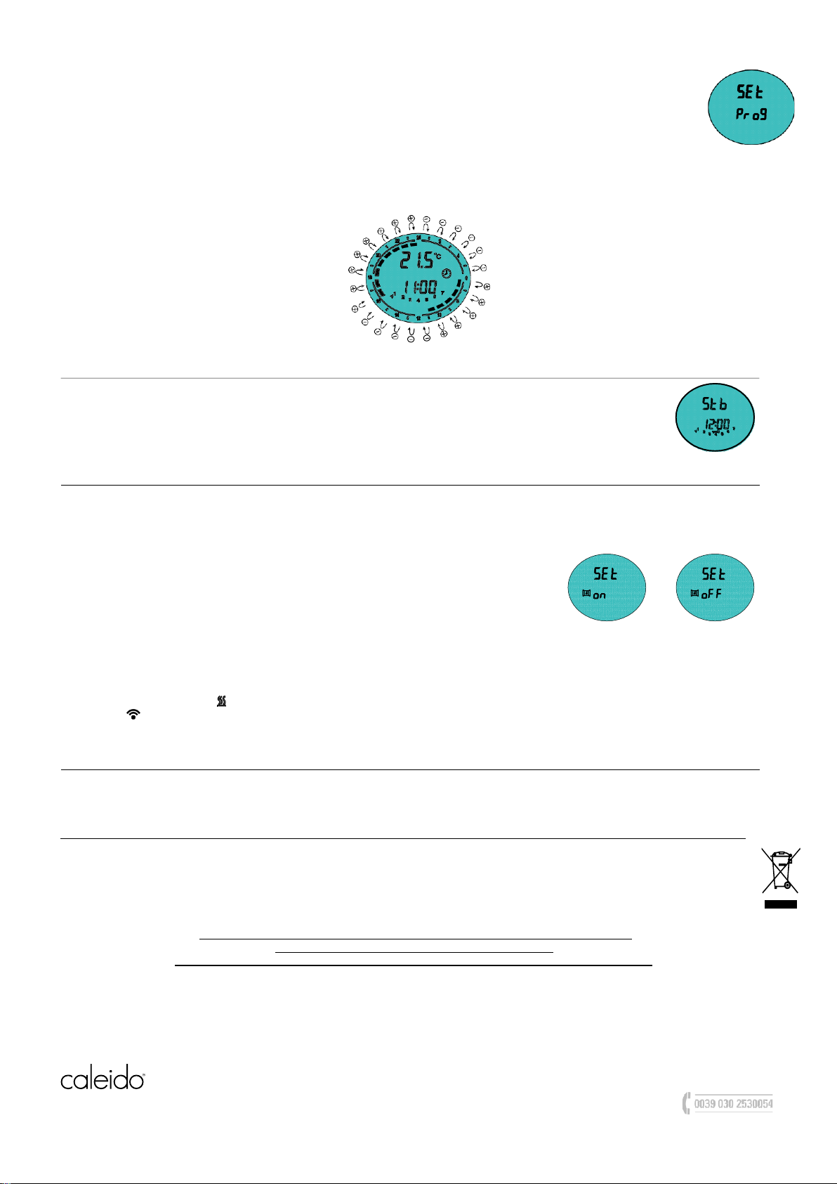
Set the current date and time
-
Activate the “Stand-by” mode and press the key for more than 3 seconds.
-
The message will appear at the top of the display: “Set”.
-
To set the current date and time, press the [+] button until tEd (time and date) appears at the bottom of the display. _View picture
-
Press the button [Prog] to enter the mode.
-
The flashing arrow indicates the current date:
Use the [+] and [-] buttons to set the current date.
-
Press the button again to confirm. The display now
shows the current time to be set.
“Hours”: use the buttons to set the hour and confirm with the [Prog] button.
“Minutes”: repeat the same procedure and confirm with the [Prog] button.
-
When the procedure is complete, the thermostat returns to “Stand-by” mode.
*
CALEIDO srl . via Pablo Neruda, 52/a . 25020 Flero (BS) . Italy
Tel +39 030 2530054 - Fax +39 030 2530533
caleido@caleido.it
caleido.it

8
"
The keypad can be locked to prevent accidental changes.
Press the button [Prog]f or 3 seconds to lock the keypad except for the [On / Stand-by] button. The “Key Lock”
icon is shown on the display.
To unlock the keypad, press the button [Prog] for 3 seconds, the key lock icon disappears from the display.
Pictured right: Example of an active ”'Key Lock” function during “Stand-by” mode.
*
b)
Set the programme in Chrono mode
-
Enter “Stand-by” mode and press the [-] button for more than 3 seconds.
-
The following word will appear at the top of the display: “Set”
To set the time sequence of the “Chrono” mode, press the [+] button until the word Prog (programming) appears at the bottom of
the display. _ See picture
-
Press the button [Prog] to enter the mode.
Now a time sequence can be set for each day of the week.
Start with day 1, select the required sequence with the [+] and [-] buttons to choose, for each hour, between “Comfort” temperature (full
bar) [+] button and “Night” temperature (empty bar) [-] button.
See picture below for reference.
Press [Prog] to confirm the setting of the first day and repeat the same procedure for the remaining 6 days of the week.
KEY LOCK FUNCTION
OPEN WINDOW SENSOR FUNCTION
The “open window sensor” function enables the device to detect if the window in the room is opened by a sudden drop in temperature. In this
case, the device deactivates the heating element for a maximum of 30 minutes.
At the end of 30 minutes or if the room temperature rises, the thermostat is reactivated.
To activate this function:
-Activate "Stand-by” mode.
-Press the [+] button for 3 seconds.
-Press the [+] button to activate or deactivate the function.
-Press the [Prog] button to confirm and return to stand-by mode.
When the function is activated, the "open window" symbol remains permanently lit.
When the device detects the open window, the symbol flashes.
When the function is deactivated, the symbol disappears.
Function activated Function deactivated
note: the device may not detect the opening of a window.
This can happen when the thermostat is in an isolated location away from draughts or close to a heat source other than the device, or if the
change in ambient temperature is too slow.
N.B. 1: when the symbol " " is on, the heating element is activated.
N.B. 2: " this icon indicates that the signal is being received from the remote control.
N.B. 3: In the event of a power failure, the thermostat configuration remains in the memory for 5 minutes.
REMOTE CONTROL (optional)
Musa Plus is equipped with an IR receiver, which is why it can be operated using the remote control (optional). All the functions
described above are also available on the remote control.
DISPOSAL
This appliance is NOT normal household waste. It must be disposed of through the appropriate recycling points. In the event of
replacement, it can be returned to your distributor.
This end-of-life management will enable us to preserve our environment and curb the consumption of natural resources.
This symbol applied to the product indicates the obligation to deliver it to a special waste
collection centre for disposal in compliance with Directive 2002/96/EC (WEEE).
The manufacturer reserves the right to make any changes it deems necessary to
improve its product at any time without prior notice.
Repairs must be carried out by authorised personnel to avoid invalidation of the warranty
CALEIDO srl . via Pablo Neruda, 52/a . 25020 Flero (BS) . Italy
Tel +39 030 2530054 - Fax +39 030 2530533
caleido@caleido.it
caleido.it
This manual suits for next models
1
Table of contents