Calex PyroMiniBus Series Manual

PyroMiniBus Series
Operator’s Guide

2
PyroMiniBus non-contact infrared sensors measure temperatures from -20°C to 1000°C and
provide an RS485 Modbus RTU interface.
The sensors are capable of being used in ambient temperatures up to 120°C without cooling
(XCF models: 70°C). They may be connected directly to third-party Modbus Masters, and they
are compatible with the optional PM180 6-channel touch screen interface, which provides
temperature display, data logging, alarms and analogue outputs.
A 6-channel junction box (model PMBHUB) is available to easily connect PyroMiniBus sensors
to the PM180 as a complete temperature measurement system.
SENSOR SPECIFICATIONS
Model Numbers
Field of View Model Number
2:1 PMB21
20:1 PMB201
Close Focus (Ø3.5 mm at distance 50 mm) PMBXCF
General
Interface RS485 Modbus RTU
Accuracy ±1% of reading or ±1°C whichever is greater
Repeatability ± 0.5% of reading or ± 0.5°C whichever is greater
Emissivity 0.2 to 1.0
Response Time 125 ms (90% response)
Spectral Range 8 to 14 μm
Supply Voltage 24 V DC (minimum sensor voltage 6 V DC, maximum 28 V DC)
Supply Current 50 mA max.
Baud Rate 9600 baud *
Format 8 data bits, no parity, 1 stop bit *
Mechanical
Construction Stainless Steel
Dimensions 18 mm diameter x 45 mm long (excluding cable gland)
Thread Mounting M16 x 1 mm pitch
Cable Length 1 m standard, longer cable available to order
Weight with 1 m Cable 85 g
Environmental
Environmental Rating IP65
Ambient Temperature 0°C to 120°C (XCF models: 70°C)
Relative Humidity 95% max. non-condensing
* Other configurations available upon request

3
ACCESSORIES
A range of accessories to suit different applications and industrial environments is available.
These may be ordered at any time and added on-site.
• Fixed mounting bracket
• Adjustable mounting bracket
• Air purge collar
• Laser sighting tool
• Junction box for 6 sensors
• PM180 6-channel touch screen interface module with data logging
• Analogue output module
• Relay output module
• Protective window in stainless steel holder
OPTIONS
The following options are available. Options are factory installed and must be ordered with
the sensor.
• Certificate of calibration
• Longer cable (up to 30 m factory-fitted; cable may be extended by user)
OPTICS
The optical charts below indicate the nominal target spot diameter at any given distance
from the sensing head and assume 90% energy.
Sensors may be used at longer distances than these diagrams show.
Thread M16
x 1 mm
Standard
length:
18
1000 45
13 12
Ø 18.6
Air Purge Collar
Sensing Head
4
18
Ø 40 Ø 29
25
1/8" BSP
air fitting
Mounting Nut
(included)
Ø 18
50
Removable spigot
fitted to type APSN
for use with -201
and -XCF models.
Not fitted to type
APSW for -21
models.
11.9
0
Spot Dia.
(inches)
Spot Dia.
(mm)
Distance: Sensor to object (inches)
Distance: Sensor to object (mm)
61.9
111.9
0.5
2.4
4.4
048
100 200
D:S 2:1
PMB21
Distance: Sensor to object (inches)
Distance: Sensor to object (mm)
11.9
36.9 61.9
0.5
1.5 2.5
0 19.7 39.4
0 500 1000
Spot Dia.
(inches)
Spot Dia.
(mm)
D:S 20:1
PMB201
Distance: Sensor to object (inches)
Distance: Sensor to object (mm)
11.9 3.5 50
0.5
0.14 2
027.9
050 200
Spot Dia.
(inches)
Spot Dia.
(mm)
PMBXCF
DIMENSIONS

4
INSTALLATION
The installation process consists of the following stages:
• Preparation
• Mechanical installation
• Electrical installation
Please read the following sections thoroughly before proceeding with the installation.
PREPARATION
Ensure that the sensor is positioned so that it is focused on the target only.
DISTANCE AND SPOT SIZE
The size of the area (spot size) to be measured determines the distance between the sensor
and the target. The spot size must not be larger than the target. The sensor should be
mounted so that the measured spot size is smaller than the target. We normally recommend
that the target should be at least twice the size of the measured spot for maximum accuracy.
AMBIENT TEMPERATURE
The sensor is designed to operate in ambient temperatures from 0°C to 120°C (XCF models:
70°C).
Avoid thermal shock. Allow 20 minutes for the unit to adjust to large changes in ambient
temperature.
ATMOSPHERIC QUALITY
Smoke, fumes or dust can contaminate the lens and cause errors in temperature
measurement.
In these types of environment the air purge collar should be used to help keep the lens clean.
ELECTRICAL INTERFERENCE
Do not operate the sensor near large electromagnetic fields (e.g. around arc
welders, generators and induction heaters). Electromagnetic interference can cause
communication errors.

5
WIRING
Check the distance between the sensor and the Modbus Master. If necessary, the sensor can
be ordered with a longer cable attached.
POWER SUPPLY
Be sure to use a 24 V DC power supply. The maximum current draw is 50 mA per sensor.
MECHANICAL INSTALLATION
All sensors come with a 1 m cable and a mounting nut. The sensor can be mounted on
brackets or cut outs of your own design, or you can use the fixed and adjustable mounting
bracket accessories which are shown below.
Note: The sensor must be grounded at only one point, either the cable shield or the sensor
housing, but not both.
AIR PURGE COLLAR
The air purge collar below is used to keep dust, fumes, moisture, and other contaminants
away from the lens. It must be screwed in fully. Air flows into the 1/8” BSP fitting and out of the
front aperture. Air flow should be no more than 5 to 15 litres/min.
Clean or ‘instrument’ air is recommended.

6
SHIELDING
PyroMiniBus sensors use a shielded cable. The RS485 network bus cable and junction boxes
should also be shielded.
Avoid ground loops. Ensure there is only one path to ground from any point on the network
shielding.
Note: The sensing head metalwork forms part of the shield.
Ensure the PWR- wires of all sensors and GND of all output modules are connected to the
Signal Ground of the Modbus Master (or PWR- of the PM180 Modbus Master interface) and
the 0 V of the sensor power supply.
For more information on electrical connections to the PM180, including how to connect the
Modbus Slave interface, please see the PM180 section of this Operator’s Guide.
IMPORTANT
Do not connect or disconnect Modbus devices with power on. Always disconnect power
before modifying electrical connections.
SENSOR WIRE COLOUR CODES:
WIRE COLOUR WIRE IDENTITY
Red PWR+
Black PWR-
White RS+
Green RS-
MODBUS OVER SERIAL LINE (RS485)
INTERFACE SUPPORTED FUNCTIONS
Baud rate 9600 Read register 0x03, 0x04
Format 8 data, No parity, 1 stop Write single register 0x06
Reply delay
(ms)
20 Write multiple register 0x10
ELECTRICAL INSTALLATION
This diagram shows how to connect the sensors and output modules to a Modbus Master,
such as a Modbus PLC, SCADA system, Calex Panel PC or PM180 touch screen terminal.
Up to 247 slave devices, such as PyroMiniBus sensors and output modules, can be connected
to the same Modbus network.

7
LIST OF MODBUS REGISTERS
The list below includes all available addresses on the PyroMiniBus sensor.
R = Read, W = Write
Address Length (words) Description R/W
0x00 1 Sensor Type (17 for PyroMiniBus) R
0x01 1 Field of view 0 for 2:1; 1 for 20:1 R
0x02 2 Serial number R
0x04 1 Modbus slave ID (slave address) R/W
0x05 1 Reflected Energy Compensation 0 for Off; 1 for On R/W
0x06 1 Reflected Temperature R/W
0x07 1 Emissivity Setting (1 LSB = 0.0001)
Minimum 0.2000, Maximum 1.0000
R/W
0x08 1 Hold Mode 0 for Off; 1 for Peak; 2 for Valley R/W
0x09 1 Hold Period (1 LSB = 0.1 seconds)
Minimum 0.1 seconds, Maximum 1200.0 seconds
R/W
0x0A 1 Average Period (1 LSB = 0.1 seconds)
Minimum 0.1 seconds, Maximum 60.0 seconds
R/W
0x0B 1 Average Temperature R
0x0C 1 Minimum Temperature R
0x0D 1 Maximum Temperature R
0x0E 1 Filtered Temperature R
0x0F 1 Unfiltered Temperature R
0x10 1 Sensor Temperature R
0x11 1 Status (bits active high)
Bit 0: Measurement error
Bit 1: Sensor temperature low
Bit 2: Sensor temperature high
Bit 3: Object temperature low
Bit 4: Object temperature high
R
0x16 1 Reflected Temperature (not saved to non-volatile
memory)
R/W
0x17 1 Emissivity Setting (not saved to non-volatile
memory)
R/W
Notes:
1 All temperature are in tenths of degrees C
2 With the exception of addresses 0x16 and 0x17, all write operations are saved to non-
volatile memory
3 For further information please refer to http://www.modbus.org/specs.php
4 Use address 255 to communicate with any connected sensor (only one sensor
connected)
5 Use address 0 to broadcast to all connected sensors (no response expected)

8
OPERATION
Once the sensor is in position and the power, air, water, and cable connections are secure,
the system is ready for continuous operation by completing the following simple steps:
1 Turn on the power supply
2 Turn on the Modbus Master
3 Read / monitor the temperature
IMPORTANT
BE AWARE OF THE FOLLOWING WHEN USING THE SENSOR:
• If the sensor is exposed to significant changes in ambient temperature (hot to cold,
or cold to hot), allow 20 minutes for the temperature to stabilise before taking or
recording measurements.
• Wires must be connected only to the appropriate terminals.
• Do not damage the cable, as this could provide a path for moisture into the sensor.
• Do not open the sensor housing. This will damage the sensor and invalidate the
warranty.
MEASURED TEMPERATURES
Average Temperature
The Unfiltered Temperature, averaged over the Average Period
Minimum Temperature
The lowest measured temperature during the Hold Period
Maximum Temperature
The highest measured temperature during the Hold Period
Filtered Temperature
The measured temperature, including Averaging and Hold Processing
Unfiltered Temperature
The “raw” measured temperature without Averaging or Hold Processing
Sensor Temperature
The temperature inside the sensor body - this is usually a few degrees higher than the
ambient temperature.
SETTINGS
Settings can be modified via the PM180 or another Modbus Master.
Emissivity Setting
The emissivity setting should match the emissivity of the target surface. This can be
determined experimentally by comparing measurements with a trusted contact probe, or
estimated using an emissivity table.
Non-reflective non-metals, such as rubber, foods, thick plastics, organic materials and painted
surfaces, generally have a high emissivity, around 0.95. This is the default setting.
Bare, clean metal surfaces can have a very low emissivity, and are often difficult to measure
accurately. If possible, a measurable area of the surface should be painted or coated to
reduce reflections and increase the emissivity.
If the emissivity setting is being updated is being updated continuously by the Modbus
Master, use address 0x17 instead of 0x07 to preserve the sensor’s non-volatile memory.
Reflected Energy Compensation & Reflected Temperature
In most applications, the target surface has the same surroundings as the sensor (for

9
example, it is in the same room). In this case, Reflected Energy Compensation should remain
Disabled for an accurate measurement.
However, if the sensor is positioned outside an oven or furnace, with the target object inside,
the reflection of the hot furnace interior can affect the measurement. In this case, Reflected
Energy Compensation should be turned ON and Reflected Temperature should be set to the
temperature inside the oven or furnace.
If Reflected Temperature is being updated continuously by the Modbus Master, use address
0x16 instead of 0x06 to preserve the sensor’s non-volatile memory.
Average Period
To slow the response time of the sensor, or to reduce fluctuations or noise on the
measurement, enter an averaging period here.
Hold Mode / Hold Period
If required, hold processing can be applied by setting Hold Mode to “Peak” or “Valley” and
setting the hold period. This is useful if the temperature reading is interrupted by gaps
between moving objects (e.g. on a conveyor), or by an obstruction.
LENS CLEANING
Keep the lens clean at all times. Any foreign matter on the lens would affect measurement
accuracy. Blow off loose particles (if not using the air purge accessory) with an air ‘puffer’.
TROUBLESHOOTING
Symptom Probable Cause Solution
No output No power to sensor Check power supply and wiring
Inaccurate measured
temperature
Target too small for
sensor’s field of view
Ensure the sensor’s view is
completely filled by the target.
Position the sensor closer to the
target to measure a smaller area.
Target is a reflective
metal surface
Use a lower emissivity setting, or
measure a non-reflective area, or
paint or coat a measurable area of
the target to make it non-reflective
Field of view obstruction Remove obstruction; ensure sensor
has a clear view of target
Dust or condensation
on lens
Ensure lens is clean and dry. Clean
gently with a soft lens cloth and
water. If problem recurs, consider
using an air purge collar.
Communication error Incorrect Modbus Slave
Address
Check the Modbus Slave Address
of the sensor and ensure it is set
correctly in the Modbus Master

10
PM180 TOUCH SCREEN INTERFACE MODULE
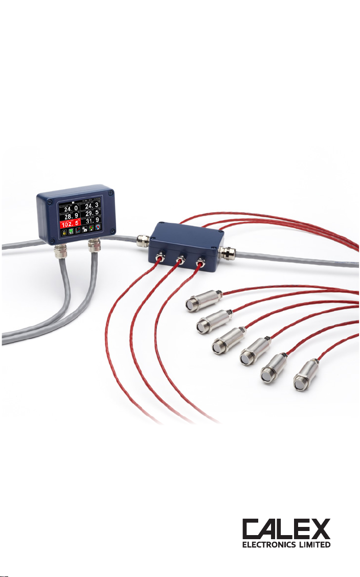
The PM180 is a temperature indicator, data logger, alarm
unit and configuration tool for Calex infrared temperature
sensors. It is compatible with all models in the PyroBus and
PyroMiniBus series, as well as all PyroMini and FibreMini
models with Modbus output.
The PM180 functions as the Modbus Master on an RS485
network of up to 6 temperature sensors, and can itself be
connected as a slave device to another RS485 network via
a second, isolated Modbus interface. This allows multiple
PM180 units to be multi-dropped to create a large network of
sensors and displays.
Optional alarm relay modules allow the PM180 to be connected to alarm equipment such as
sounders and beacons, and optional analogue output modules allow it to be connected to
non-Modbus instrumentation.
All the configurable parameters for the hub, the connected sensors and the optional output
modules are adjustable via the PM180’s built-in resistive touch screen interface, which can be
operated even with gloves on.
With an optional MicroSD Card inserted, the PM180 functions as a fully-configurable data
logger.
SPECIFICATIONS
Touch Screen Display 2.83” (72 mm) resistive TFT, 320 x 240 pixels, backlit
Supply Voltage 10 to 30 V DC
Maximum Current Draw 100 mA
Ambient Temperature Range 0°C to 60°C
Relative Humidity Maximum 95%, non-condensing
Configurable Parameters
(global)
Temperature units, date and time, data logging, graph
channels, alarm logging
Configurable Parameters (per
channel)
Signal processing, emissivity setting, reflected energy
compensation, alarms, Modbus address
Alarm Configuration 12 alarms (2 per sensor) with adjustable level,
individually configurable as HI or LO.
Temperature Units °C or °F selectable
Temperature Resolution 0.1° below 1000°; 1° above 1000°
Signal Processing Average, peak hold, valley hold, minimum, maximum
Display Sample Period 120 ms per device (720 ms in total for 6 devices)
Compatible Sensor Types PyroBus (all models),
PyroMiniBus (all models),
PyroMini (-BB and -BRT models),
FibreMini (–BRT models)
Compatible Output Module
Types
ICP DAS M-7061 12-channel relay output module,
ICP DAS M-7024 4-channel analogue output module,
selectable V/mA
Dimensions 98(w) x 64(h) x 36(d) mm excluding cable glands
Weight 280 g

11
DATA LOGGING
With an optional MicroSD Card installed in the slot inside the PM180, data logging may be
manually started and stopped via a button on the temperature display screen, or scheduled
to begin at a pre-determined time via the Settings menu.
If the PM180 is connected via the slave interface to another Modbus network, logging may
also be started remotely by the Modbus Master on that network.
DIMENSIONS
PMBHUB JUNCTION BOX - SPECIFICATIONS
Construction Die Cast Aluminium
Electrical Connections Removable screw terminals, 28 AWG to 18 AWG
Weight 250 g
Environmental Rating IP65
PM180
Touch Screen
Module
PMBHUB
Junction Box

12
ELECTRICAL CONNECTION

13
ELECTRICAL INSTALLATION
The PM180 has removable screw terminal blocks for its Modbus Slave and Modbus Master
interfaces.
1 Connect the Master interface to the sensors and output modules. Be sure to check the
power supply requirements of each device before applying power.
2 Optionally, connect the Slave interface to another Modbus network with its own Modbus
Master such as a PLC or SCADA system.
Isolation is provided between the Slave and Master interfaces.
Ensure the shielding of the RS485 network is continuous from the sensors to the Modbus
Master. There should be only one possible path to ground from any point on the shielding. If
necessary, introduce strategic breaks in the shielding (e.g. at junction boxes).
MICROSD CARD AND BATTERY
The MicroSD Card and battery slots are located on the touch screen circuit board. Unscrew
the lid of the PM180 to access them.
The battery is optional. With a battery fitted, the internal clock will continue to run when the
power is off. Without a battery, the unit will request the date and time each time the power is
cycled.
All other settings are stored in the unit’s permanent memory and will be preserved when it is
switched off, regardless of whether a battery is fitted.
USING THE TOUCH SCREEN INTERFACE
Visit www.calex.co.uk/PM180 for help on how to use the touch screen interface, including a
diagram showing how to navigate to each setting and set up the optional output modules.
By default, the PM180 is locked and the Settings menu is greyed out. To access the Settings
menu, unlock the PM180. The default password is 1234. After entering the password, tap the
Unlock icon to unlock the unit. The password can be changed via the touch screen interface.
FIRST-TIME CONFIGURATION
1 The first screen displayed on the PM180 is the Sensor List. The list is empty by default.
2 Tap “Add Device” to add a sensor.
3 Enter the Modbus address of the sensor to be added. The factory-set Modbus address is
shown on a tag attached to the sensor.
4 Select the type of sensor and tap Apply (the green checkmark).
5 Repeat “Add Device” process for the remaining connected sensors and tap the Exit icon
to start measuring temperatures.
CHANGING A SENSOR’S MODBUS ADDRESS
Provided each Modbus address is unique, there should be no need to change the addresses
of the connected sensors. If required, it can be done as follows:
1 On the PM180 interface, browse to Settings - Modbus Master - Sensor List
2 Tap the desired sensor to enter the Sensor Settings menu, then Modbus Address.
3 Enter the new Modbus Address for that sensor. The new address will be applied when
the power is cycled.
4 Cycle the power.
If the changed sensor is no longer communicating with the PM180 (shown by a red
temperature display), it is because the PM180 is still looking for the previous address. To
resolve this, remove and add the sensor to the Sensor List:
1 Browse to Settings - Modbus Master - Sensor List
2 Tap the sensor that is no longer communicating, then tap Remove Device
3 On the Sensor List, tap Add Device and enter the Modbus address of the new sensor. Be
sure to select the correct sensor type.

14
MODBUS OVER SERIAL LINE (RS485)
INTERFACE SUPPORTED FUNCTIONS
Baud rate 9600 Read register 0x03, 0x04
Format 8 data, No parity, 1 stop Write single register 0x06
Reply delay (ms) 20 Write multiple register 0x10
The list below includes all available addresses (R = Read, W = Write):
Address Length
(words)
Description R/W
0x0000 1 MODBUS slave ID (slave address) of PM180 R/W
0x0001 7 Device identification string in ASCII R
"PM180vx.xx" where x.xx is the firmware version
0x0008 2 Serial number R
0x000A 2 Data acquisition sample interval (1 to 86400 seconds) R/W
0x000C 2 Number of samples to be logged (0 to 86400 samples) -
note: enter 0 to log continuously
R/W
0x000E 1 Data acquisition enabled (0 for disabled, 1 for enabled) R/W
0x000F 1 Data acquisition start time: Hours (0 to 23) R/W
0x0010 1 Data acquisition start time: Minutes (0 to 59) R/W
0x0011 1 Data acquisition start time: Seconds (0 to 59) R/W
0x0012 1 Data acquisition start time: Day (1 to 31) R/W
0x0013 1 Data acquisition start time: Month (1 to 12) R/W
0x0014 1 Data acquisition start time: Year (2012 to 2105) R/W
0x0015 1 Alarm log settings R/W
Bit 0 - Log trigger time
Bit 1 - Log while triggered
Bit 2 - Log acknowledge time
Bit 3 - Log reset time
0x0020 1 Remote request - Start logging R/W
Write 1 - request start of data logging
Read 1 - request pending, Read 0 - no request pending
0x0021 1 Remote request - Stop logging R/W
Write 1 - request termination of data logging
Read 1 - request pending, Read 0 - no request pending
0x0022 1 Remote request - Acknowledge alarms R/W
Write 1 - request acknowledgement of alarms
Read 1 - request pending, Read 0 - no request pending
0x0023 1 Remote request - Reset alarms R/W
Write 1 - request reset of alarms
Read 1 - request pending, Read 0 - no request pending
NOTES:
1 For further information please refer to http://www.modbus.org/specs.php
2 Use address 255 to communicate with any connected unit (only one sensor connected)
3 Use address 0 to broadcast to all connected units (no response expected)

15
ACCESSING CONNECTED SENSORS VIA ANOTHER MODBUS MASTER
If the PM180 is connected to another Modbus Master, such as a Modbus PLC or SCADA, the
entire sub-network (the PM180, the connected sensors and output modules) appears as a
single Modbus Slave device to the PLC or SCADA. The Modbus Slave ID (Modbus Address) is
that of the PM180.
The temperatures and settings of the sensors connected to that PM180 can be read by
adding the following offsets to the sensor’s own Modbus register addresses. The Sensor Index
is the position of the sensor in the PM180 sensor list. The Sensor Index numbers correspond
to the positions of the sensors on the PM180 screen as follows:
0 1
2 3
4 5
Sensor Index Address offset (hex) Address offset (decimal)
0 0x1000 4096
1 0x1100 4352
2 0x1200 4608
3 0x1300 4864
4 0x1400 5120
5 0x1500 5376
Example
To read the Filtered Temperature on a PyroMiniBus sensor in position 4 on the PM180 as
shown above, read from register 0x0E + 0x1400 = 0x140E = decimal 5134.
For information on the Modbus addresses for other compatible sensors, please see the
Operator’s Guide for that sensor.
MAINTENANCE
Our customer service representatives are available for application assistance, calibration,
repair, and solutions to specific problems. Contact our Service Department before returning
any equipment. In many cases, problems can be solved over the telephone. If the sensor is
not performing as it should, try to match the symptom below to the problem. If the table does
not help, call Calex for further advice.
GUARANTEE
Calex guarantees each instrument it manufactures to be free from defect in material and
workmanship under normal use and service for the period of two years from the date of
purchase. This guarantee extends only to the original buyer according to Calex Terms and
Conditions of Sale.

Calex Electronics Limited
PO Box 2, Leighton Buzzard, Bedfordshire, England LU7 4AZ
Tel: +44 (0)1525 373178 Fax: +44 (0)1525 851319
Issue E - Jul 2018
This manual suits for next models
3
Table of contents
Other Calex Accessories manuals
Popular Accessories manuals by other brands

CharlesWater
CharlesWater 99026 Installation, operation and maintenance

NuAire
NuAire NU-5810 Operation and maintenance manual

Argo
Argo Joy instructions

Giropes
Giropes BAXTRAN BR95 user manual

PrimaLuceLab
PrimaLuceLab EAGLE4 user manual

ROSE DISPLAYS
ROSE DISPLAYS ANOGOTCHA FRAME ROUND WITH CABLE AND SAUCER manual