Calex PyroNFC Series Manual

PyroNFC Series
Operator’s Guide

The PyroNFC is a non-contact infrared temperature sensor with Near Field Communication
(NFC) capability. It has linear voltage and open collector alarm outputs for connection to
industrial process instrumentation.
By touching an NFC-enabled smartphone against the back of the sensor, the user can
congure the sensor’s settings, and read the measured temperature, via a free app.
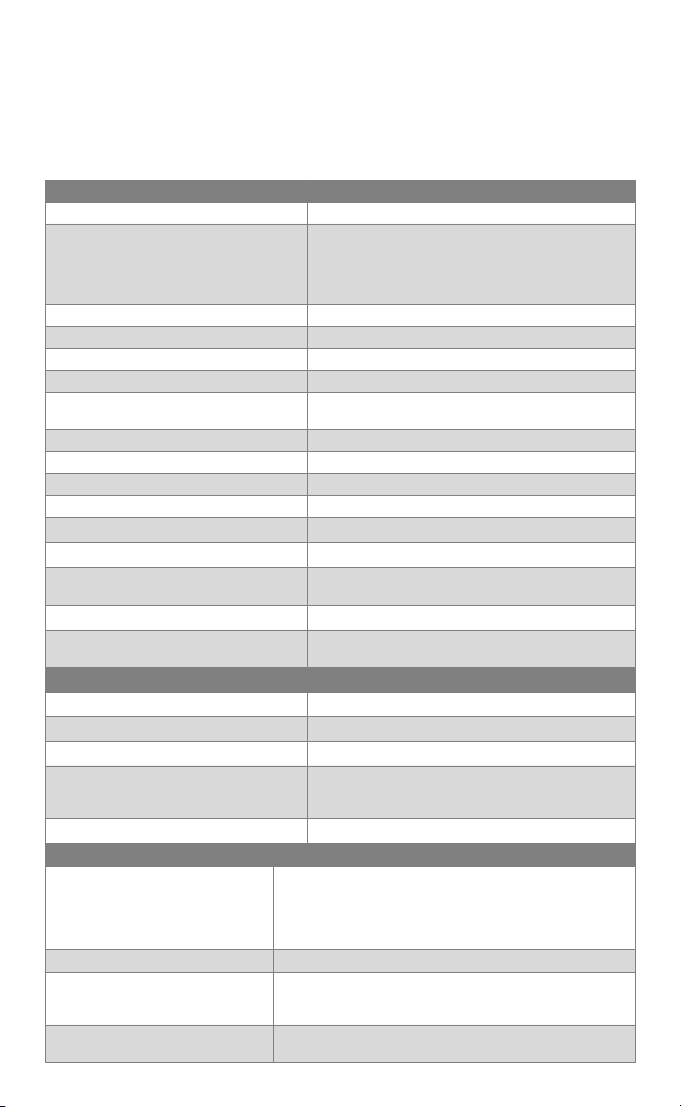
SPECIFICATIONS
General
Temperature Range 0 to 1000°C
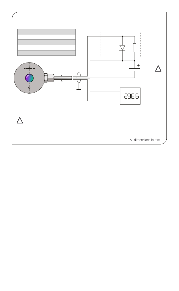
Outputs Model PN151: 0-5 V DC, 1-5 V DC or 0-10 V
DC output, linear with measured temperature,
congurable and rescalable via NFC
Model PN151K: Type K Thermocouple
Field of View 15:1 (see OPTICS)
Accuracy ± 1.5% of reading or ± 1.5°C, whichever is greater
Repeatability ± 0.5% of reading or ± 0.5°C, whichever is greater
Response Time 125 ms
Conguration Via iOS or Android app using NFC-equipped
device (e.g. smartphone or tablet)
Emissivity Setting Adjustable via app
Emissivity Setting Range 0.2 to 1.0
Max Temperature Span (Linear Output) 1000°C
Min Temperature Span (Linear Output) 100°C
Spectral Range 8-14 µm
Max. Supply Voltage 28 V DC
Min. Supply Voltage (at Sensor) 12 V DC (for 10 V output)
6 V DC (for 5 V output)
Max Current Draw 7 mA
Warm Up Time (PN151K) Allow 10 seconds after power-on before a reading
is observed.
Environmental & Conformity
Environmental Rating IP65
Ambient Temperature Range 0°C to 80°C
Relative Humidity 95% max. non-condensing
Electromagnetic Compatibility (EMC) EN61326-1, EN61326-2-3 (Electrical Equipment
for Measurement, Control and Laboratory Use -
EMC Requirements - Industrial)
RoHS Compliant Yes
App
Congurable Parameters Temperature range
Linear voltage output type and scale
Alarm output threshold and hysteresis
Emissivity setting
Reected temperature
Temperature Units °C / °F
Signal Processing Averaging Period (0.125 to 60 seconds)
Peak / Valley Hold
Hold Period (0.125 to 120 seconds)
Real Time Temperature Reading Hold NFC device against sensor for continuous in- app
temperature updates
2

Mechanical
Construction Black anodised aluminium and ABS
Cable Length 1 metre standard (longer lengths available to order)
Weight with 1 Metre Cable 65 g
ACCESSORIES
Accessories may be ordered at any time and added on-site. The following accessories are
available:
Fixed mounting bracket - Adjustable mounting bracket - Air purge collar
OPTIONS
Options are factory-installed and cannot be retrotted. The following options are available:
Certicate of Calibration - Extended cable
INSTALLATION
The installation process consists of the following stages:
Preparation - Mechanical installation - Electrical installation
Please read the following sections thoroughly before proceeding with the installation.
PREPARATION
Ensure that the sensor is positioned so that it is focused on the target only.
AMBIENT TEMPERATURE
The sensor is designed to operate in ambient temperatures from 0°C to 80°C.
Avoid thermal shock. Allow 20 minutes for the unit to adjust to large changes in ambient
temperature.
ATMOSPHERIC QUALITY
Smoke, fumes or dust can contaminate the lens and cause errors in temperature
measurement. In these types of environment, the air purge collar should be used to help keep
the lens clean.
Sensor
CORRECT
INCORRECT
Target larger
than measured
spot
Target smaller
than measured
spot
Background
Distance: Sensor to object (inches)
Distance: Sensor to object (mm)
943 76
0.4 1.7 3.0
0 19.7 39.4
0500 1000
Spot
Diameter
(inches)
(mm)
D:S 15:1
OPTICS
The sensor may be used at longer
distances than shown, and will measure a
larger spot. The measurement accuracy is
not aected by the measurement distance.
There is no maximum measurement
distance provided the air between the
sensor and target is free of obstructions.
DISTANCE AND SPOT SIZE
Mount the sensor at a distance where the
measured spot size is smaller than the
target.
The spot size must not be larger than the
target.
3

Fixed Mounting Bracket Adjustable Mounting Bracket
ELECTRICAL INTERFERENCE
To minimise electromagnetic interference or ‘noise’, the sensor should be mounted away from
motors, generators and such like.
WIRING
Check the distance between the sensor and the measurement instrumentation. If necessary,
the sensor can be ordered with a longer cable attached.
POWER SUPPLY
Check the supply voltage is between 6 V DC and 28 V DC.
To use the 0-10 V output, the supply voltage must be at least 12 V DC.
IMPORTANT: Ensure the power supply is only connected to the PWR+ and PWR- wires, and the
polarity is correct, before switching the power on.
Do not switch the power o and on again quickly. If the power is switched o, allow 15
seconds before switching it back on.
MECHANICAL INSTALLATION
All sensors come with a 1 metre cable and two mounting screws. The sensor can be mounted
on brackets or cut-outs of your own design, or you can use the xed and adjustable mounting
bracket accessories which are shown below.
The supplied mounting screws are for use with a panel or bracket at least 2 mm thick. The
screws are 8 mm long.
Between the mounting holes, there must be a hole to allow the sensor a clear view through
the panel or bracket. This hole must be larger than the lens of the sensor or the aperture of
the air purge, if used. Use as large a hole as possible.
Note: The sensor must be grounded at only one point, either the cable shield or the mounting
screws, but not both.
MOUNTING BRACKETS
31.0 31.0
7.0
9.0
22.0
2 x Mounting Holes M4 Clearance
24.0
25.0
15.0
60°
60°
50.0
33.5
9.0
49.0
49.0
Ø13.5 Clearance 4 x Mounting Holes Ø3.2
All dimensions in mm
4

AIR PURGE COLLAR
The air purge collar is used to keep dust, fumes, moisture, and other contaminants
away from the lens. It ts between the sensor and the mounting surface. Longer
screws are provided for use with a panel or bracket at least 2 mm thick.
Air ows into the hose barb tting and out of the front aperture. Air ow should be 5
to 15 litres/min.
Clean or ‘instrument’ air is recommended.
All dimensions in mm
ELECTRICAL INSTALLATION AND DIMENSIONS
Wire Colours and Tags
14.0
Ø13.5
Ø31.0
2 x Hole
Ø3.2
Section A-A
A
A
21.5
THIS FACE
AGAINST
SENSO
AI
OUT
Air Inlet
Hose barb
Ø 5 mm
+-
Touch NFC
smartphone here
Field of view (see OPTICS)
PWR+
PWR-
OP+
0 V
21.5
31.0
29.0
13.3
2 x mounting holes
M3 x 0.5 mm
Depth 7 mm
Ø 3.2
nominal
Output 0 to 5 V DC or
0 to 10 V DC for
display or controller
Power
supply
6 to 28 V DC
Open collector output for alarm
0 to 24 V DC, 50 mA
Protection
diode
AL
PN151 (Voltage Output)
Red PWR+ Power Supply +
Blue PWR- Power Supply - (0 V)
Yellow AL Open Collector Alarm
Output
Green OP+ Linear Voltage Output +0-5
or +0-10 V DC
!
!
Caution! Check the identication tags and ensure all
wiring is correct before applying power to the sensor.
5

+
-
PWR+
PWR-
OP+
-
Ø 5.5
nominal
Type K
Thermocouple
output for
display or
controller
Power
supply
6 to 28 V DC
Open collector output for alarm
0 to 24 V DC, 50 mA
Protection
diode
AL
OP-
Ensure Cold Junction Compensation is enabled in the display or controller.
If you extend the Type K output wires, ensure Type K thermocouple cable and connectors are used.
Using copper or other metals will aect the accuracy of the measurement.
OPERATION
Once the sensor is in position and the appropriate power, air and cable connections are
secure, the system is ready for continuous operation by completing the following simple
steps:
• Turn on the power supply
• Turn on the measurement instrument
• Read / monitor the temperature
CONFIGURATION AND READING TEMPERATURES
The sensor is fully congurable via a smartphone or tablet with NFC capability. Download the
free app for Android devices from the Google Play Store, or for iOS devices from the Apple
App Store (search “PyroNFC”)
Touch the NFC device against the back of the sensor to read the measured temperature. On
Android, the reading updates continuously while the phone is touching the sensor. On iOS,
the temperature is updated once each time the user taps “update” in the app.
The sensor must be powered to read the measured temperature with the app.
To change settings, edit the conguration parameters in the app, then tap “Write to Sensor”.
Touch the NFC device against the back of the sensor to write the settings. A message will
appear in the app to conrm the settings have been written successfully.
Allow at least 5 seconds for the new settings to take eect. There is no need to power the
sensor to read or write the settings.
CONFIGURATION (MODEL PN151K):
The Type K thermocouple output has a temperature range of 0 to 1000°C. This is not
rescalable.
The settings in the app for conguring the voltage output type and scale on models with
linear voltage output have no eect on PyroNFC-K models with Type K thermocouple output.
Select the correct sensor model from the drop-down list in the app to hide these options.
PN151-K (Thermocouple Output)
!
!
Caution! Check the identication tags and ensure all wiring is correct
before applying power to the sensor.
Red PWR+ Power Supply +
Black PWR- Power Supply -
Purple OP- Type K output -
Green OP+ Type K output +
Yellow AL Alarm output
Wire Colours and Tags
6
All dimensions in mm

IMPORTANT
Be aware of the following when using the sensor:
• If the sensor is exposed to signicant changes in ambient temperature (hot to cold, or cold
to hot), allow 20 minutes for the temperature to stabilise before taking or recording
measurements.
• Do not operate the sensor near large electromagnetic elds (e.g. around arc welders or
induction heaters). Electromagnetic interference can cause measurement errors.
• Wires must be connected only to the appropriate terminals.
• Ensure the sensor is grounded at one point: either the cable shield termination, or
the mounting screws, but not both.
• When the power is switched o, allow at least 15 seconds before switching the power back
on.
LENS CLEANING
Keep the lens clean at all times. Any foreign matter on the lens would aect measurement
accuracy. Blow o loose particles (if not using the air purge accessory) with an air ‘puer’.
MAINTENANCE
Our customer service representatives are available for application assistance, calibration,
repair, and solutions to specic problems. Contact our Service Department before returning
any equipment. In many cases, problems can be solved over the telephone. If the sensor is not
performing as it should, try to match the symptom below to the problem. If the table does not
help, call Calex for further advice.
TROUBLESHOOTING
Symptom Probable Cause Solution
No output No power to sensor Check power supply and wiring
Inaccurate measured
temperature
Target too small for
sensor’s eld of view
Ensure the sensor’s view is completely lled
by the target. Position the sensor closer to
the target to measure a smaller area.
Target is a reective
metal surface
Measure a non-reective area, or paint or
coat a measurable area of the target to
make it non-reective
Field of view
obstruction
Remove obstruction; ensure sensor has a
clear view of target
Dust or condensation
on lens
Ensure lens is clean and dry. Clean gently
with a soft lens cloth and water. If problem
recurs, consider using an air purge collar.
Incorrect wire
connections
Check wire colour codes
Erroneous
temperature (voltage
output)
Output temperature
scale mismatch
Re-scale input temperature range on
measurement instrument to match sensor
Erroneous
temperature
(thermocouple
output)
No Cold Junction
Compensation (CJC) or
wrong type of
extension cable
Enable CJC on measurement instrument;
ensure extension cable and connectors are
of the correct thermocouple type
7

DEFAULT SETTINGS
The PyroNFC is fully congurable via an iOS / Android app. No conguration is necessary: the
sensor will work straight out of the box using the below default settings.
All settings are adjustable except those marked (xed).
GUARANTEE
Calex guarantees each instrument it manufactures to be free from defect in material
and workmanship under normal use and service for the period of two years from the date
of purchase. This guarantee extends only to the original buyer according to Calex’s standard
Terms and Conditions of Sale.
Setting Range of Values Default Value
(PN151)
Default Value
(PN151K)
Output Voltage* 0-5 V / 1-5 V / 0-10 V 0-10 V Type K
thermocouple (xed)
Temperature Low* 0°C to 900°C 0°C 0°C (xed)
Temperature High* 100°C to 1000°C 1000°C 1000°C (xed)
Alarm Trigger High / Low / O High High
Alarm Monitor
Temperature
Target / Internal Target Target
Alarm Set Point 0°C to 1000°C 30°C 30°C
Alarm Hysteresis 0°C to 30°C 1°C 1°C
Alarm Mode Active High / Active
Low
Active High Active High
Alarm Reset Auto / Manual Automatic Automatic
Emissivity Setting 0.2 to 1.0 0.95 0.95
Reected Energy
Compensation
On/O O O
Reected
Temperature
0°C to 1000°C 25°C 25°C
Averaging Period 0.125 s to 60 s 0.125 s 0.125 s
Hold Mode Peak/Valley/O O O
Hold Period 0.125 s to 120 s 250 ms 250 ms
* These settings are not adjustable on model PN151K.
Calex Electronics Limited
PO Box 2, Leighton Buzzard, Bedfordshire, England LU7 4AZ
Tel: +44 (0)1525 373178 | mail@calex.co.uk | www.calex.co.uk
Issue E - Apr 2022
8
Table of contents
Other Calex Accessories manuals