DECLARATION OF CONFORMITY
according to the
Low Voltage Directive, 2006/95/EC, the EMC Directive, 2004/108/EC, including amendments
by the CE marking Directive, 93/68/EC
Product Type designation
Cab heater Slim Line 1400
The following harmonised European standards or technical specifications have been applied :
Standards Test reports issued by Regarding
EN 60335-1 2002+A11+A1+A12+A2 SEMKO electrical safety
SEMKO 110-1968 mod. 1-4 SEMKO electrical safety
EMKO-TUB (311) N201 / 81 SEMKO electrical safety
SEMKO 111-1967 mod. 1-4 SEMKO electrical safety
EMKO-TUB (321) N251 / 81 SEMKO electrical safety
SEMKO 111FE-1979 mod. 1-5 SEMKO electrical safety
EMKO-TUB (321) No279 / 91 SEMKO electrical safety
EN 50366:2003+A1 SEMKO EMF
EN 55014-1:2006 SEMKO EMC-emission
EN 61000-3-2:2006 SEMKO EMC-emission
EN 61000-3-3:1995+A1+A2 SEMKO EMC-emission
EN 55014-2:1997+A1 SEMKO EMC-immunity
– The products comply with the LVD safety standards as per above.
We have an internal production control system that ensures compliance between the manufac-
tured products and the technical documentation.
– The products comply with the harmonised EMC standards as per above.
The products is CE marked in 2008.
As manufacturer, we declare under our sole responsibility that the equipment follows the
provisions of the Directives stated above.
Eskilstuna, August 04, 2008
Bo Norlin
President
ENGLISH
Technical information
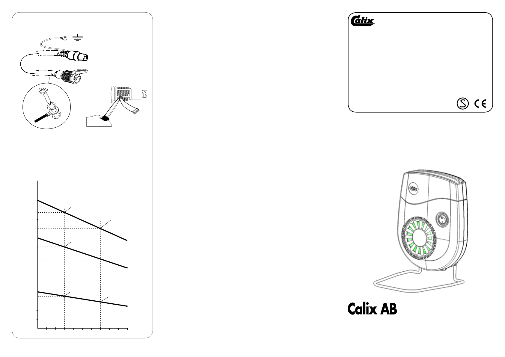
Car Heater Calix Slim Line 800 and 1400 has one output position, 800 or 1400
Watt at -25°C. Calix Slim Line 1800 has two output positions 1100 or 1800 Watt
at -25°C. The car heater’s heating coil is of the type that adjusts the output
according to ambient temperature and air flow, see diagram figure 4. The figure
shows the output during free air flow. If there are objects such as the seat, wall,
etc. that obstruct air flow, then the output is reduced.
Normal manufacturing tolerances also affect output.
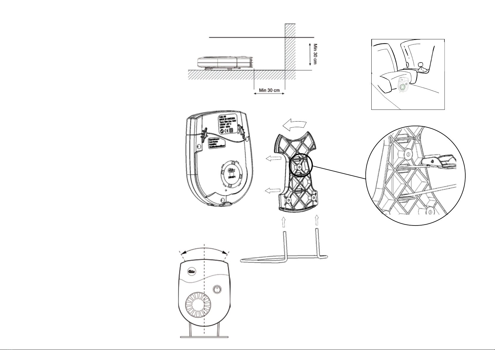
It is important that the car heater is mounted according to minimum distance stated
in figure 1. The car heater shall be connected to 230 Volt AC.
Dimensions (800 & 1400): 178 x 140 x 46,5 mm.
Dimensions (1800): 178 x 140 x 58,5 mm.
Installation
The car heater designed for placement on the cab floor using the supplied stand
or with the supplied bracket for permanent installation. A suitable placement
may be the middle console, transmission tunnel or side wall by the leg space.
Determine a location where the car heater where it cannot cause injury in case
of a collision and bolt it to the bracket. Note that the car heater may not be bolted
in a position where it can be hit by the air bag in case of a collision. Check with
your local automotive workshop or car dealer where the best place is for installing
the car heater as there may be sensitive equipment behind the compartment
trim. The car heater may only be connected to a grounded socket inside the
car. The ground connection must be a continuous from the car heater’s casing,
the car’s body all the way to the grounded power socket. Installation is easily
performed using Calix installation parts with plug-in couplings, according to the
following points.
• If there is no engine heater, supplement with inlet cable, extension cable and cab
wallsocket.Install theappliancesocket in asuitablelocationwhereit is protected
from splash and mechanical damage. The appliance socket is constructed for
external installation and is provided with a weak point in the material, allowing
you to punch a hole to drain any water that has entered. The inlet cable has a
separate ground lead for grounding the car body. Remove the paint from the
car’s body panel. Screw the ground lead in place with the installation parts in
the following order; sheet metal screw, spring washer, cable terminal, spring
washer, see figure 2. Clamp the metal hose into place between the appliance
inlet and the cab wall socket. Install the wall socket.
• If an engine heater has been installed or is to be installed at the same time,
the installation of the car heater is most suitably done using Calix branching
cable kit, consisting of extension cable, branching outlet and cab wall socket.
See instructions for the branching cable kit.
• If the plug-in connection is not used, the installation shall be performed by a
certified electrician. The connection cable must be oil-resistant rubber cable
of a type not lighter than RDO 3 x 1.5 mm2. The cable between the cab wall
socket and the car’s appliance inlet must be routed in a metal hose. The plug
should be made of thermal plastic and of approved rinse-proof type (IP44).
Check the fuse rating (ampere) before connecting the heater and do not forget to
include the engine heater’s power in case one is installed in the car.
5 Amp fuse allowing max. power 1150 Watt
6 Amp fuse allowing max. power 1380 Watt
10 Amp fuse allowing max. power 2300 Watt
16 Amp fuse allowing max. power 3680 Watt
Important
Calix Car Heater is equipped with a resettable temperature limiter (thermostat)
that cuts off current to the heating coil and engine if the temperature exceeds
the permitted value. Among others, the temperature limiter (thermostat) can be
triggered if the heater is placed so that the air cannot circulate, e.g. if the air
outlet grate or air intake grate is covered. If the temperature limiter (thermostat)
has been triggered, the car’s cab heater will not work.
To reset the temperature limiter (thermostat) disconnect the heater from 230V for
at least 20 minutes.
In case of replacing the cable stand, the heater must be sent to Calix AB.
DEUTSCH
Technische Information
Der Fahrzeug-Heizlüfter Calix Slim Line 800 und 1400 verfügt über eine Heizstufe,
800 oder 1400 Watt bei -25 °C. Calix Slim Line 1800 verfügt über zwei Heizstufen,
1100 und 1800 Watt bei -25 °C. Der Heizlüfter ist so konzipiert, daß er die Heiz-
leistung entsprechend der Umgebungstemperatur und der Luftzirkulation regelt,
siehe Diagramm in Bild 6.Das Diagramm zeigt die Leistung bei freier Luftzirkulation.
Wird die Luftzirkulation durch beispielsweise Sitze, Wände etc. behindert, setzt
dies die Leistung herab.
Die Leistung wird auch durch normale Herstellungsdifferenzen beeinflußt. Es ist
wichtig, daß der Heizlüfter mit dem in Bild 1 angegebenen Mindestabstand montiert
wird. Der Heizlüfter ist an 230 V Wechselspannung anzuschließen.
Maße (800 & 1400): 178 x 140 x 46,5 mm
Maße (1800): 178 x 140 x 58,5 mm
Installation
Der Heizlüfter ist zur Platzierung im Fußraum mittels des mitgelieferten Standbügels
oder zum Festeinbau mittels der beiliegenden Montageplatte, siehe vorgesehen.
Eine geeignete Stelle für die Montage ist beispielsweise die Mittelkonsole, der
Kardantunnel oder die Seitenwände des Fußraumes.Wählen Sie für die Montage
eine Stelle aus, an der der Heizlüfter keine Behinderung darstellt und schrauben
Sie die Halterung fest. Beachten Sie, daß der Heizlüfter keinesfalls an einem Ort
montiert werden darf, an dem er mit dem Airbag kollidieren kann. Heizlüfter gemäß
Bild 2 an der Halterung befestigen.Durch Rücksprache mit Ihrer Autowerkstatt bzw.
Ihrem Autohändler erfragen, welcher Platz für die Montage des Heizlüfters am
geeignetsten ist, da sich hinter derVerkleidung empfindliche Fahrzeugteile befinden
können. Der Heizlüfter darf nur an eine geerdete Steckdose im Innenraum des
Fahrzeugs angeschlossen werden.Die Erdung muß vom Heizlüftergehäuse über die
Autokarosserie bis zu einem geerdeten elektrischen Stromanschluß durchgängig
sein. Die Installation erfolgt am einfachsten mit Hilfe der Calix-Anschlußteile mit
Einsteck-Kupplungen, gemäß der nachfolgend aufgeführten Schritte.
• Falls keine Motorheizung vorhanden ist, kann die Ausrüstung mit einem Calix-
Anschlußkabel, Einbaukabel, -Verlängerungskabel (nach Bedarf) und -Heizlüf-
tersteckdose komplettiert werden. Befestigen Sie die Minikontaktsteckdose an
einer Stelle, an der sie vor Spritzwasser und mechanischen Beschädigungen
geschützt ist. Die Steckverbindung ist für die Außenmontage konzipiert und
mit einer Vertiefung zum Ausbrechen von Öffnungen für das Kondenswasser
versehen, siehe Bild 3. Die Öffnung wird entsprechend der Anbringung der
Steckverbindung plaziert, damit eindringendes Wasser wieder austreten
kann. Für die Erdung des Chassis verfügt das Einbaukabel über ein separates
Erdungskabel. Lack von der Karosserie abkratzen. Erdungskabel mit Hilfe
der mitgelieferten Befestigungsteile in der folgenden Reihenfolge anbringen:
Blechschraube, Unterlegscheibe, Kabelschuh, Unterlegscheibe, siehe Bild 2.
DannMetallschlauch sichern und Heizlüftersteckdose montieren.
• Bei vorhandener Motorvorwärmung oder bei geplanter gleichzeitiger Montage
wird der Heizlüfter am einfachsten mit Hilfe des Calix-Verteilerkabelsatzes
montiert, der ausVerlängerungskabeln, Verteilerstück und Heizlüftersteckdose
besteht. Siehe Gebrauchsanweisung für den Verteilerkabelsatz.
• Werden keine Einsteck-Kupplungen verwendet, ist die Montage von einem
autorisierten Elektroinstallateur vorzunehmen. Die Elektrokabel müssen eine
ölbeständige Gummiummantelung haben und mindestens derTypklasse RDO
3x1,5 mm2 angehören. Die Leitung zwischen der Heizlüftersteckdose und der
Anschlussdose des Fahrzeugs muß mit einem Metallschlauch geschützt sein.
Der Stecker muß aus Thermoplastmaterial bestehen, zugelassen und schwall-
wasserdicht sein (IP44).
Gebrauchsanweisung
Die Leistungseinstellung muß an die vorhandene Leistung des Stromnetzes
angepaßt sein. Die Ampere-Zahl der Sicherung kontrollieren, bevor der Heizlüfter
angeschlossen wird. Falls im Fahrzeug eine Motorheizung vorhanden ist, nicht
vergessen, deren Leistung ebenfalls zu berücksichtigen.
5-A-Sicherung erlaubt höchstens 1150 Watt Stromabnahme
SUOMI
Tekniset tiedot.
CalixSlim Line800/1400 sisätilanlämmittimessä onyksi tehoa, 800/1400Wattia
ulkolämpötilassa -25°C. Calix Slim Line 1800 sisätilanlämmittimessä on kaksi
tehoa, 1100/1800 Wattia ulkolämpötilassa -25°C Sisätilanlämmittimen vastus
muuttaatehoaanympäristönlämpötilanja ilmanvirtaustenmukaan. Katso kuvan
6 käyrää. Käyrä näyttää tehon kun ilmanvirtaus on esteetön. Jos ilmavirtausta
estää esim. istuin tai seinä, vähenee lämmittimen teho.
Normaalit tuotantotoleranssit voivat myös vaikutta tehoon.
On tärkeää että huomioidaan minimietäisyydet, kuvassa 1 kun lämmitin asen-
netaan paikoilleen. Sisätilanlämmitin kytketään 230 Voltin vaihtovirtaan.
Ulkomitat (Slim Line 800 & 1400): 178 x 140 x 46,5 mm.
Ulkomitat (Slim Line 1800): 178 x 140 x 58,5.
Asennus
Sisätilalämmitinsijoitetaan ohjaamon lattialleseisomaan pakkauksessa olevalla
tukijalan avulla. Kiinteään asennukseen käytetään kiinnitysalustaa. Sopva
asennuspaikka voi olla keskikonsoli,kardaanitunneli tai jalkatilojen sivuseinä.
Sijoituspaikkavalitessaon huomioitavaetteilämmitin aiheutavahinkoa mahdol-
lisenkolarin sattuessa esim,turvatyynynläheisyyteenlämmitintä ei saaasentaa.
Tarkista huoltokorjaamoltasi että valitsemasi sijoituspaikka on turvallinen koska
esim keskikonsolin takana voi olla johtoja ja herkkää elektroniikkaa.Sisätilaläm-
mittimensaa kytkeä ainoastaan maadoitettuunpistorasiaanauton ohjaamossa.
On varmistuttava siitä maadoituskosketus on hyvä sisätilalämmittimestä ja
auton korista maadoitettuun pistorasiaan.Asennus suoritetaan parhaiten Calix
pikaliitinjärjestelmän avulla, seuraavien kohtien mukaan.
• Jos autossa ei ole moottorinlämmitintä, käytetään Calix elementtikaapelia,
Iiitäntäjohtoaja sisätilapistorasiaa. Kiinnitäpistorasiapaikkaan, jossa seon
suojatturuosteenestoruiskutukseltaja mekaaniseltavahingolta. Pistorasia
onsuunniteltu asennettavaksiautonulkopuolelleja siihen onmerkitty kohtia
vedenpoistoreikiä varten, katso kuva 3. Nämä avataan, jos pistorasian
sijainti näin vaatii, jotta pistorasiaan mahdollisesti tunkeutuva vesi voisi
valua pois. Elementtikaapelissa on asennettuna valmis maadoitusjohto.
Poistamaadoituskohdaltalika ja väri. Kiinnitämaadoitusjohto kiinnitysosien
avullaseuraavasti:peltiruuvi, tähtialuslevy, kaapelikenkä,tähtialuslevy, katso
kuva 2. Kiinnitä pistorasian ja sisätilapistorasian välinen kaapeli. Kiinnitä
sisätilapistorasia.
• Jos autossa on moottorinlämmitin, tai on tarkoitus asentaa se myös
samanaikaisesti, käytetään Calix haaroitussarja, joka koostuu kahdesta
jatkokaapelista, haaroituskappaleesta ja sisätilapistorasiasta. Katso haa-
roitussarjan asennusohjeita.
• Mikäli ei käytetä pikaliittimiä, on hyväksytyn sähköurakoitsijan suoritettava
asennus. Sähköjohtojen tulee olla vähintään tyyppiä RDO 3x1,5 mm2.
Sisätilapistorasian ja autopistorasian välisen johdon tulee olla päällystetty
metallikuorella. Pistokkeen tulee olla termomuovia, sekä hyväksytty rois-
kevesitiiviinä.
Käyttöohje
Ennen kuin kytket lämmittimen sähköverkkoon tarkista että pistorasian sulake
on riittävän suuri huomioon ottaen myös mahdollisen moottorinlämmittimen
teho.
5 Amp sulake enimmäisteho II 50 Wattia
6 Amp sulake enimmäisteho 1380 Wattia
10 Amp sulake enimmäisteho 2300 Wattia
16 Amp sulake enimmäisteho 3680 Wattia
Tärkeää
Calix sisätilalämmitin on varustettu palautettavalla lämpösulakkeella joka
katkaisee virran vastukselle ja moottorille mikäli lämpötila nousee sallittujen
arvojen.Lämpösulake voi laueta mikäli lämmitin sijoitetaan niin ettei ettei ilma
pysty kiertämään riittävän hyvin,esim jos imupuoli tai puhalluspuoli peitetään.
Jos lämpösuoja on lauennut lakkaa sisätilalämmitin toimimasta.Lämpösuoja
palautuu kuin pidät sisätilalämmitintä jännitteettömänä vähintään 20 min.
Mikäli virtajohto joudutaan vaihtamaan,niin sisätilalämmitin lähetetään Calix
Automotive Ab tai jälleenmyjälle.
6-A-Sicherung erlaubt höchstens 1380 Watt Stromabnahme
10-A-Sicherung erlaubt höchstens 2300 Watt Stromabnahme
16-A-Sicherung erlaubt höchstens 3680 Watt Stromabnahme
Wichtig
Der Calix-Heizlüfter ist mit einer rückstellbaren
Überhitzungsschutzsicherungversehen, die die Stromzufuhr zur Heizung und
zum Lüftermotor unterbrechen, wenn die zulässige Temperatur überschritten
wird. Der Überhitzungsschutz kann beispielsweise ausgelöst werden, wenn der
Heizlüfter so plaziert wurde, daß die Luftzirkulation behindert wird, z. B. durch
Abdecken der Luftaustritts-- bzw. Lufteintrittslamellen.Für die Rückstellung der
Temperatursicherung ziehen Sie den Netzstecker und lassen Sie das Gerät für
mindestens 20 Minuten abkühlen.Für den Ersatz des Anschlusskabels muss der
Heizlüfter über Ihren Händler zum Hersteller Calix AB zurückgeschickt werden.