INSTRUCTION MANUAL
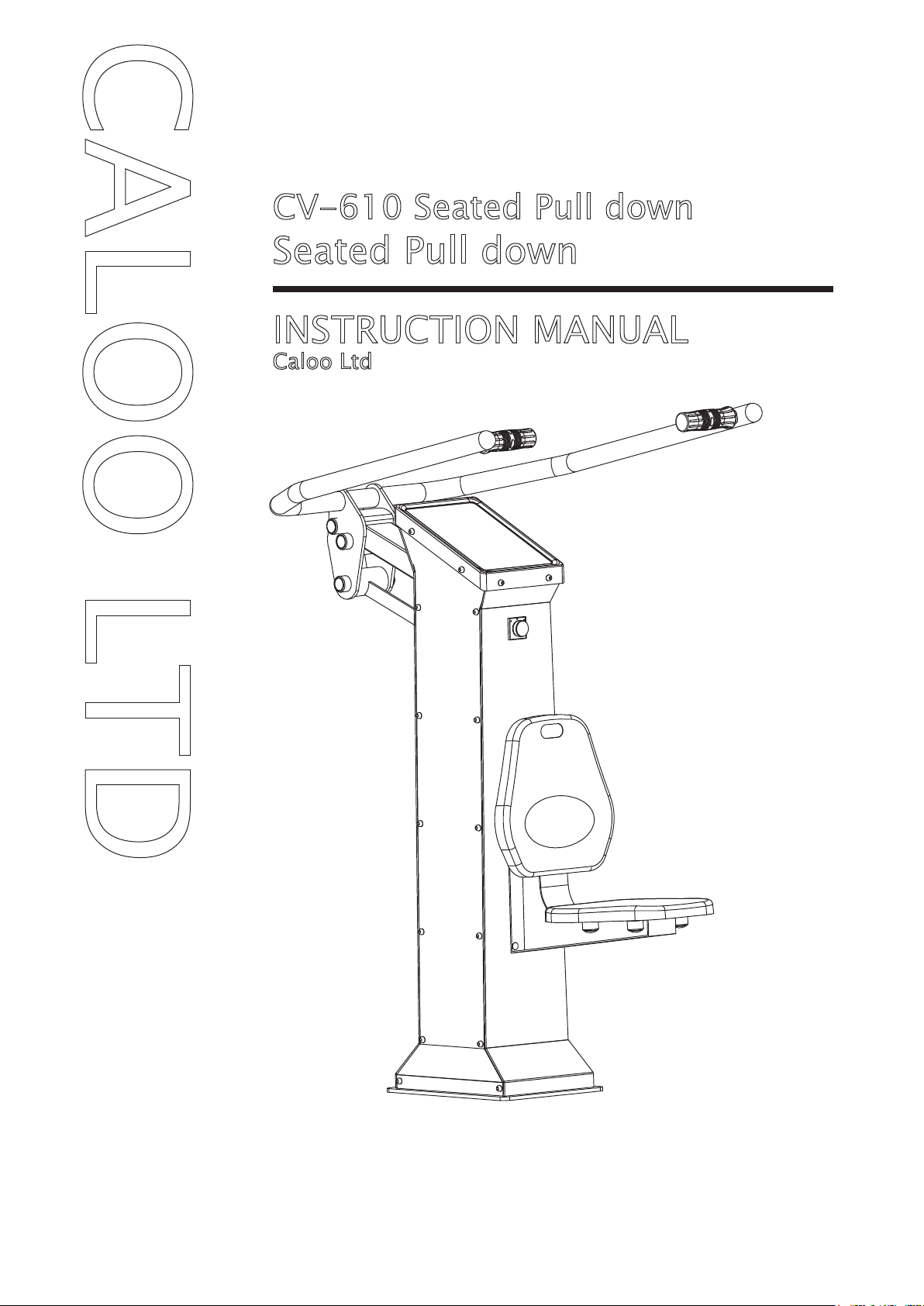
Model No.: CV-610 Seated Pull down
Caloo Ltd
Thank you for purchasing our product.
Please read this instructions before installing and exercising, and keep it for future reference.
Failure to follow instructions may cause injury to you.
WARNING
1. This unit is intended for youths and adults or users having an overall height greater than 1
400 mm.
2. Before beginning any fitness program, obtain a complete physical examination from your
physician.
3. Do not overexercise. If you feel any painful sensation or have abnormal symptoms, stop your
workout immediately and consult your physician.
4. Maximum allowed weight of a user is 150 kg. Maximum allowed number of user is one
person. Other user is prohibited to enter the training zone while the unit is in use.
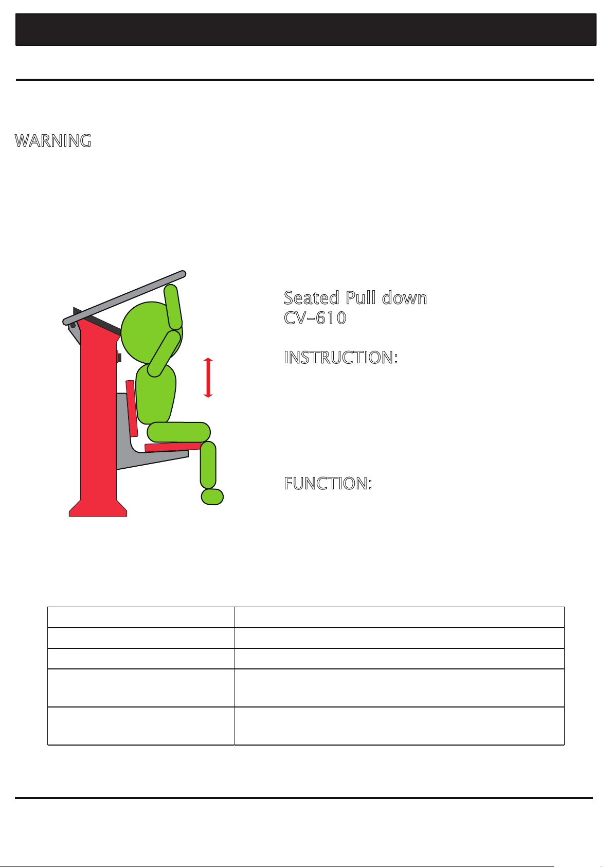
Seated Pull down
CV-610
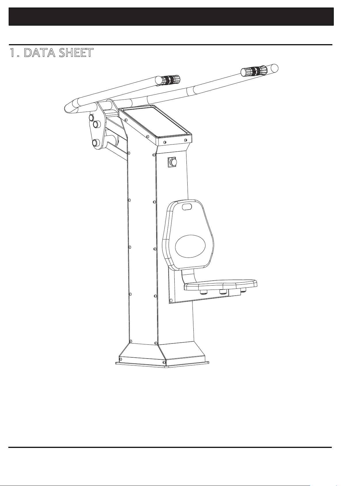
INSTRUCTION:
1. Sit and place the back against the back of the
seat.
2. Hold the handles with both hands, pulling and
pushing.
3. Turn the dial clockwise or anticlockwise to
increase or decrease your exercise difficulty.
FUNCTION:
Reinforce and develop upper limbs musculature,
chest and back improving cardiopulmonary capaci-
ty.
Safety Standard EN16630:2015
Year of Production To be completed at time of manufacture.
Manufacturer Caloo Ltd
Address Unit 12, Boxted Farm,Berkhamstead
Road, Hemel Hempstead, HP1 2SG
Contact 01442 265489